Probably every reader of this article noticed that most electrical appliances operating from a household network are designed for a voltage of 220 V/50 Hz. Hence the conclusion - these are the parameters provided to us by the electricity supplier. Unfortunately, this is not entirely true. We may assume that tap water is completely pure, but experience tells us that it contains impurities that impair the taste. The same “impurities”, in the form of additional frequencies and pulses, reach the electricity consumer. This is interference in the electrical network.
Sources of interference
Both natural phenomena and various man-made equipment can distort an alternating current sinusoid. As a result of their actions, the following occurs:
- short-term voltage dips;
- deviations from nominal frequency parameters;
- changes in electrical harmonics;
- fluctuations in current amplitude;
- HF noise;
- impulse bursts;
- common mode interference.
Let us briefly look at the main sources causing the listed deviations.
Voltage dips.
This phenomenon is a consequence of the operation of switching devices in power systems. This happens when a short circuit occurs on the lines, as a result of starting powerful electric motors, and in other cases associated with changes in load power. The presence of such short-term interference is inevitable when automatic protective equipment is triggered, and they cannot be eliminated by the electricity supplier.
Changes in frequency characteristics.
Deviation from the specified frequency occurs as a result of a significant change in the load current. If the level of energy consumed exceeds the power of the generated installations, the rotation of the generator slows down, which leads to a drop in frequency. When the load is reduced, the generation frequency increases.
Automation regulates power distribution, right up to switching off loads, but frequency interference is still present in the network.
Harmonics.
The source of this type of distortion is the presence in networks of equipment with a nonlinear current-voltage characteristic:
- converter and rectifier substations;
- arc furnaces;
- transformers;
- welders;
- TVs;
- cycloconverters and many others.
Electric motors can cause harmonic distortion, especially if they are installed at the end of a long line.
Voltage deviation
Changes in potential stability occur as a result of periodic jumps in the maximum current consumed. The source of load changes are voltage regulating devices, for example, transformers with on-load tap-changers.
A graph illustrating a short-term overvoltage is shown in Figure 2 (Fragment A - depicts a pulse surge).
RF interference.
They are created by the influence of devices operating in the high-frequency range. RF interference caused by devices that generate high-frequency signals travels over the air or through network lines.
Voltage pulses.
Asymmetry of a three-phase system.
The cause of such interference is often powerful single-phase loads, both domestic and industrial. They cause phase angle shifts and amplitude mismatches. By turning off the power to powerful current-consuming devices, you can eliminate the problem.
Surge Protectors
If the supplied voltage in the network does not meet the specified standards, the stabilizer normalizes it. In addition, the stabilizer repeats the functions of a good surge filter: protection against short circuits, overvoltage and high-voltage pulses, as well as noise filtering. Low-power stabilizers can be installed for a separate electrical appliance, for example, for a refrigerator, since this device reacts most painfully to power surges. Super-powerful stabilizers are installed for the entire network; such models are most useful for country houses or in areas where there are constant problems with voltage.
In 220 Volt networks, single-phase stabilizers are used, in 380 Volt networks - three single-phase or one three-phase. Although a good stabilizer costs several times more than a surge protector, it actually protects equipment from serious voltage surges and ensures stable operation.
220 volt surge protection device for home
Overvoltage protection 220 V is a task that you will have to solve yourself: think with your head and assemble the protection with your own hands. Modern household and computer equipment operate safely from 190 to 240 V. A voltage surge creates devastating consequences for equipment when the voltage instantly increases significantly and drops sharply.
The most common causes of overvoltage:
- simultaneous switching off/on of a large number of devices;
- 0-wire damage;
- lightning strikes power lines;
- wire breakage by an external object;
- violation of the wiring diagram in the switchboard.
The industry produces a large list of devices that can reliably provide protection from overvoltage of a 220 V network, and household appliances from damage and high network parameters:
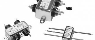
- VKN (voltage control relays) are installed when voltage surges are a rare occurrence. RKN - a device that turns off the electrical circuit when the potential difference changes and turns it on when the network parameters are normalized, must have its own power exceeding the total power of the connected equipment.
- DPV (voltage drop sensor) is triggered when the potential difference changes. The DPN causes a current leak, which is detected by another machine - the RCD, which also turns off the network.
How does a surge protector work?
Filtering of unnecessary signal components is carried out, oddly enough, by special filters; they are assembled from inductors (L) and capacitors (C). Limitation of high voltage surges - varistors. This works thanks to such electrical concepts as time constant and commutation laws, reactance.
The time constant is the time it takes for a capacitor to charge or an inductance to store energy. Depends on filter elements (R, L and C). Reactance is the resistance of elements, which depends on the frequency of the signal, as well as on their value. Present in inductors and capacitors. It is caused only by the transfer of alternating current energy to an electric or magnetic field.
In simple words, with the help of reactance you can reduce and limit the high-frequency harmonics of our sinusoid. It is known that the power frequency in the outlet is 50 Hz. This means you need to calculate the filter for frequencies an order of magnitude higher or more. The resistance of an inductor increases with increasing frequency, while that of a capacitor decreases. That is, the principle of operation of the network filter is to suppress high-frequency components of the network sinusoid, while having minimal impact on the main 50 Hz component.
Causes of conducted interference
Malfunctions of technical equipment, like interference, are unpredictable. This is explained by both the many different mechanisms of interference occurrence and the statistical nature of noise immunity in the predominant number of automation equipment.
The reasons for the appearance of conducted EMF in the system, that is, the mutual influence of devices or conductive elements, include:
- supply voltage with a frequency of 50 Hz;
- HF and LF clock signals;
- signals in control wires or data transmission lines (TL);
- switching processes in inductances;
- spark discharges at the moment of closing and opening contacts.
Given the reasons for the appearance of conducted EMFs, they can have different meanings.
In the next article we will look at methods of protection against electromagnetic, including conducted, interference.
What problems can arise with the electrical network?
As many people know, the electricity generated by domestic networks and distributed to users' outlets is alternating current with a frequency of 50 hertz and a voltage of 220 volts. In principle, small deviations are allowed in the parameters, so the permissible operating range of 50-60 hertz and 220-230 volts most often appears on electrical appliances.
However, in reality, the current parameters in the outlet may differ significantly. At the same time, the greatest danger is not long-term deviations, but single episodes of short-term sharp increases in voltage, decreases in voltage, frequency changes, as well as moments of complete power outage for a fraction of a second.
What are the reasons for such failures? They are extremely diverse. There are poor performance of local electrical networks, dilapidated wiring of old houses, violations of the laying of power lines in new buildings, and the use of low-quality materials (wires, distribution equipment) during construction. In addition, sudden changes in voltage can be affected by the weather, neighbors turning on some powerful (in terms of energy consumption) device, plugging in a faulty device, and so on. Simply put, it is impossible to deal with possible failures in the power grid using any specific methods. We need universal solutions.
Methods of protection
Unfortunately, we cannot control the quality of the power grid, but it is quite possible to protect household appliances. Depending on what distortions a particular electrical device is sensitive to, the appropriate protection method is chosen. Various external devices, built-in electrical circuits, as well as shielding of structural elements and grounding help reduce noise levels.
An example of interference suppression is shown in Figure 3.
The following external devices are effective:
- Surge Protectors;
- IPB;
- frequency converters;
- adjustable transformers;
- network filters and filter cascades (the schematic diagram of a simple filter is shown in Figure 4).
Particularly difficult is the suppression of high-frequency impulse distortions in the range of several tens of MHz. Often, protection applied directly to the source of interference is used for these purposes.
The use of voltage stabilizers is justified in cases of regular voltage dips in the home network. If the current is consistently too low or too high, it is better to use a transformer.
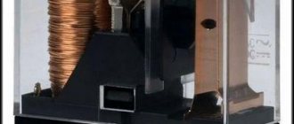
Uninterruptible power supplies have a high level of protection for computers and other sensitive electronics. Figure 5 shows a photo of an uninterruptible power supply to protect a computer.
These devices implement several protective functions, but the main one is supplying power to the devices for several minutes, followed by their correct shutdown. In order to achieve the maximum level of protection, it is logical to give preference to an uninterruptible power supply.
Purpose of a surge protector
It is known that you have an AC power supply of 220 Volts in your outlet. “Alternating voltage (current)” means that its magnitude and/or sign are not constant, but change over time according to a certain law.
The nature of generating electrical machines (generators) is such that a sinusoidal EMF is generated at the output terminals. However, everything would be fine if all devices were resistive in nature, there were no inrush currents, and did not contain pulse converters. Unfortunately, this does not happen, because... Most devices are inductive, capacitive in nature, brushed motors, and switching secondary power supplies. This whole convoluted set of words is the main culprit of electromagnetic interference.
We started the article by talking about electromagnetic interference for a reason. These interferences “spoil” the even shape of the sinusoid. So-called harmonics are formed. If we expand the real signal from the socket in the form of a Fourier series, we will see that the sine wave has been supplemented with various functions of different frequencies and amplitudes. The voltage waveform in a real outlet has become far from ideal.
So what's the end result? Poor power supply is a problem for radio transmitting devices. Simply, your TV or radio will experience interference. In addition to interference from consumers, the network contains interference of random origin that we cannot predict. These are surges, voltage drops due to power outages, switching on a powerful load, etc.
A surge protector is needed in order to:
- Filter out interference to cleanly power devices.
- Reduce interference from power supplies.
Using network filters
The alternating voltage coming from the industrial network is characterized by a signal frequency of 50 Hz. When you plug in devices or start engines, signal harmonics with a frequency of less than 50 Hertz or higher than this value penetrate into the electrical network. Such harmonics affect the operation of pulsed equipment, forcing it to operate in extreme conditions. A power filter is used to cut off spurious frequencies. Passive radioelements are used as filter elements:
- capacitor;
- throttle;
- varistor;
- self-resetting fuse.
A capacitor is connected in parallel with the load. It does not allow direct current to pass through, while alternating current passes through it unhindered. The larger the capacitance of the capacitor, the less distortion of the sinusoidal signal will pass through it. This is characterized by the time of discharge and charge. Thus, as the frequency changes, the reactance of the capacitor also changes.
A varistor or nonlinear resistor is a semiconductor device with a nonlinear current-voltage characteristic. Depending on the level of the applied signal, its resistance changes. During normal operation, the varistor has a high resistance and does not affect the passing signal. If a voltage surge occurs, its resistance decreases, the input circuit is bypassed and the entire peak current passes through it. It is connected, like a capacitor, in parallel with the load.
Types of power filters
A power filter, smoothing out voltage surges and frequency distortions, is often used as an extension cord with the ability to connect several devices at the same time. You can find filters of different types and different price ranges on sale. The main requirements for them are to reduce the amount of various types of interference and maintain safety of use. They differ primarily in their characteristics:
- operating voltage;
- maximum power;
- methods of protection;
- operating voltage;
- additional features.
The maximum power value shows how much load the filter can simultaneously withstand. The filter radio elements used determine the method of protection. Additional features include backlit power buttons, the number of sockets, the presence of outputs for connecting telephone devices, USB outputs, while the filters are available with wires of different lengths. Power filters are produced in dielectric housings that are resistant to heat and shock.
Selecting a filter for protection
Using a low-quality surge protector not only does not improve the supply voltage parameters, but also leads to a short circuit or fire. Before purchasing, you will need to decide what kind of protection it should provide, whether it will be used as an extension cord, and the total peak power of the devices planned for connection. You should choose from well-known manufacturers whose products are certified and safe.
- Defender DFS 501. The best choice. The device has six sockets with a grounding contact with a power of 10A, two USB ports with a stabilized voltage of five volts. The sockets are made with protective shutters to protect connected devices from short circuits, overloads, and parasitic high-frequency signals. The length of the wire is two meters. In addition, the device is equipped with a status indicator.
- Pilot S 014. Economical solution with reliable contact in the socket. Includes basic protection elements and operation indication. Has six 10A outlets. Wire length 5 meters.
- Sven SV-0231018GR Pro. It is equipped with eight sockets with a grounding contact. The body is made of ABS plastic. In addition to standard inductive-capacitive protection, it has a varistor and an automatically reset fuse in the circuit. Wire length 1.8 meters.
- Daesung MC2345. Although it has only four sockets, each is equipped with a switch and is designed for a current of 16 amperes. Consists of high quality copper cable five meters long. Excellent performance against overload protection. Polycarbonate body, non-marking. The manufacturer gives a 5-year warranty, and does not carry out repairs, but replaces them with a new one.
- ERA USF-5es-1.5mB. The protective filter consists of 5 sockets. Protects wiring and equipment from damage due to power surges. The load current is 10A. All electrically conductive parts are made of copper. The length of the wire is one and a half meters.
Internet Industry Library I2R.ru
Today we will talk about a problem as old as Ilyich’s light bulb - interference in the domestic power grid. Or more precisely, about network filters, devices that can solve this problem.
Tested:
|
|
Let's start with the main thing: with the answer to the question “what is a surge protector?” As practice shows, not all users know the correct answer and confuse the concepts of “surge filter” and “network extender”. And this does not happen by chance. Usually the manufacturers themselves mislead us by calling an ordinary power strip a filter.
So, a network filter is a device containing a varistor filter to suppress impulse noise and a notch filter to suppress high-frequency noise. The extension cord has neither one nor the other.
Today we will try to most fully present the range of the domestic network filter market, and also show in practice the differences between filters and extension cords.
Glossary of terms
Pulse interference
— short-term (10–6–10–9 s) voltage surge in the network with an amplitude of over 4000–6000 V. Pulse interference is caused by natural and man-made sources. A natural source of impulse noise is lightning strikes near cables or power lines (can cause harm at a distance of up to 20 km). Technogenic causes - switching processes when turning on or off a powerful network load, current surges when the voltage in the network is completely turned on/off, accidents at substations. The voltage values of switching pulses even in household networks can reach 20 kV.
Varistors are used to suppress impulse noise.
High frequency interference (RFI)
- a signal of uncertain amplitude and duration in the range of 100 Hz - 100 MHz, which distorts the sinusoid of the standard voltage in the network and, thus, negatively affects the operation of any electrical equipment. Sources of RF interference are various electrical devices: electric motors, generators, welding machines, etc.
Notch filters are used to suppress RF interference.
Varistor
- This is a semiconductor resistor. The resistance of a varistor depends nonlinearly on the amplitude of the applied voltage: the higher the voltage, the lower the resistance. The basic principle of operation of a varistor is very simple. The varistor is connected in parallel with the protected equipment, i.e., during normal operation, the same voltage is applied to it as to the protected device. In operating mode (in the absence of impulse noise), the current passing through the varistor is negligible, and therefore the varistor under these conditions is an insulator. When a high voltage pulse occurs, the resistance drops sharply. Thus, the varistor protects the load by dissipating the pulse energy in the form of heat. At this moment, a current of several thousand amperes can flow through the varistor. After the pulse is extinguished, the resistance of the varistor again becomes very large.
To fully protect devices in a two-wire network with protective grounding (namely, computers and office equipment are connected to this type of network), varistors must be connected between phase and zero, phase and protective grounding, as well as zero and protective grounding. This connection circuit is called a varistor triangle.
Notch filter
is a functional block designed to attenuate the signal amplitude in a certain frequency band. The frequency band in which the notch filter attenuates the signal amplitude is called the notch band. The frequency at which maximum amplitude attenuation occurs is the center frequency of the notch filter. The level of signal attenuation at the center frequency is the rejection depth (measured in dB).
Notch filters are used to suppress high-frequency interference.
APC Surge Protector P5T-RS
APC is known to Russian consumers primarily for its UPS. But its product range is not limited to uninterruptible power supplies. The two APC network filters taking part in testing are direct confirmation of this.
The design of the Surge Protector P5T-RS is classic: five sockets are mounted in one row in an elongated rectangular case made of gray plastic.
All sockets have protective curtains. At the end of the case there are two RJ–45 telephone connectors. Two fuses “insure” the varistor protection of the telephone line.
You never know what can happen... The results of a quick external inspection indicate the absence of an automatic fuse that protects against excess load current. A detailed examination of the electronic filling confirms this fact: the Surge Protector P5T-RS has one 15 A fuse for protection against overload and short circuit. In addition to the fuse, the device is equipped with a varistor triangle and a notch filter, made in the form of a ready-made unit enclosed in a single housing. The telephone line is protected from impulse noise by two additional varistors and two fuses.
The filter assembly is careless: the board is not completely cleaned of flux, the soldering of the elements is done sloppily.
APC Surge Arrest E20-G
The model attracts attention with its appearance. The semicircular body of impressive size not only pleases the eye, but also suggests a solid electronic filling. The filter housing is designed to ensure convenient installation of power cables of connected devices.
In addition to the standard LED indicating that the device is connected to the network, on the front panel of the Surge Arrest E20-G there is an indicator of a break in the protective grounding, i.e. if there is no grounding in the electrical network, you can always find out about this by simply turning on the Surge Arrest E20-G.
E20-G is the only filter where the power wires are attached to the board with terminals, and even insulated.
The “internals” of this filter make a very good impression.
The developers took the suppression of impulse noise extremely seriously: the E20-G board has 6 varistors installed (a record number among all tested devices). The notch filter, which includes two large chokes with ferrite cores, looks no less impressive. A 10 A automatic fuse that protects against overload is backed up by two fusible fuses against short circuits. The careful installation of elements on the board can serve as a model for all other manufacturers.
Impressive, right?
But this is not the limit: two free seats for RJ-45 connectors hint that there are more advanced modifications of the E20-G. Despite the abundance of varistors, capacitors and chokes in the RF interference suppression tests, the E20-G looked extremely pale. This fact is most likely explained by the discrepancy between Western and domestic standards for RF interference suppression. Apparently, in the range of 10–100 MHz the E20-G should show more impressive results. But, unfortunately, we did not have equipment that could be used to test the characteristics of filters in the frequency range above 2 MHz.
Defender Surge Protector Advance
Defender Surge Protector Advance is a typical “pseudo filter”; it does not contain a notch filter, and only one varistor is used as protection against impulse noise. Actually, this varistor is the only difference between the Defender Surge Protector Advance and a regular extension cord.
The design of the model is standard: a rectangular case with five Euro sockets, a switch and a power indicator located on the top cover.
The insides of the Surge Protector Advance are not rich in detail for the reasons already mentioned. Apart from the varistor, there is only one part inside that is worthy of mention - a 10 A automatic fuse.
The soldering of the elements was carried out carelessly: huge drops of frozen solder and flux that was not completely washed off. This most likely will not affect the consumer qualities, but you should not count on a high rating in the “Constructive” category for this model.
Defender Surge Protector Phone/Fax/Modem
This filter is the “big brother” of the Advance model. Fortunately, the differences between the models are not only the presence of two RJ-45 telephone connectors on the Phone/Fax/Modem.
As protection against impulse noise, Defender Surge Protector Phone/Fax/Modem uses a standard circuit of three varistors - a varistor triangle. Two additional varistors are installed to protect the telephone line. To protect against RF interference, there is a notch filter at the input, made in the form of a ready-made unit.
Despite the fact that the element base in the Defender Surge Protector Phone/Fax/Modem is practically no different from similar filters (for example, Sven Gold or APC Surge Protector P5T-RS), in the RF interference suppression test this filter showed the best result in the category “rejection bandwidth” and one of the best in the “rejection depth” category.
Surge Protector Phone/Fax/Modem has an additional LED indicator to indicate the health of the varistor protection.
Like the Advance, the Phone/Fax/Modem uses a 10 Amp fuse for overload protection plus an additional fuse link for short circuit protection.
Unfortunately, this model suffers from the same assembly defects as the Defender Surge Protector Advance: sloppy soldering, unwashed flux and general negligence (some plastic parts have clearly visible traces of temperature exposure).
Defender GA01R
This filter has the most original design among the models under consideration. Defender GA01R is a network splitter (double) with a plug mounted directly into the device body.
Despite its small size, the GA01R contains a varistor delta and two more varistors to protect the telephone line.
Unfortunately, there is no notch filter, but the ability to effectively suppress impulse noise is an undoubted achievement for such a compact device. Not bad for such a little thing, isn't it?
To protect against short circuits and overloads, the Defender GA01R has a 10 A fuse.
The assembly deserves praise: the soldering is neat, the board is thoroughly cleaned of flux.
On Tech Universal
On Tech Universal can easily be called a high-power network extender (maximum load capacity is 3.3 kW).
This device does not contain a notch filter and is not capable of combating RF interference. To reduce impulse noise, one varistor is installed in parallel with the phase and working zero. Unfortunately, for complete protection against impulse noise, a varistor alone is not enough.
For short circuit and overcurrent protection, On Tech Universal uses a 15 A automatic fuse-disconnector.
Despite the modest filling, inspection of the internals of On Tech Universal left a pleasant impression. The assembly is done very carefully and does not raise any complaints.
Pilot Pro
The Pilot brand is an old-timer in the surge protector market. For many users, the name Pilot has become a household name, symbolizing any surge protector in general (just as the name Sound Blaster was once synonymous with the words “sound card”).
The Pilot Pro's body is made of black and white plastic and is shaped like an airplane fuselage. The “aviation” similarity is enhanced by a special “wing” - a block that is docked to the body and is designed for ergonomic laying of the wires of the connected load. At the whim of the designers, this block actually looks like a wing.
The device has two indicators, one of which signals that the device is connected to the network, and the second indicates a malfunction of the varistor filter protection.
Inside the case there is a notch filter, which includes two impressive chokes and a voltage limiter block consisting of 4 varistors.
The Pilot Pro has dual overload and short circuit protection - a 10A automatic fuse and fuses.
A huge capacitor and two chokes are our answer to RF interference.
A distinctive feature of the Pilot Pro is the presence of a plastic ring in the front of the filter, into which the power cable is built. The ring is located on a plastic sleeve and can rotate around its axis in a horizontal plane. As a result, the cable moves freely relative to the Pilot Pro body.
There are no complaints about the assembly of the Pilot Pro - soldering and installation were done neatly.
Pilot SPA
To be fair, we note that Pilot SPA is not a classic surge protector. Pilot SPA has the same consumer properties as “pseudo filters” (which also take part in our testing), but has such a useful property as overvoltage protection.
The design of the Pilot SPA is not the best.
Structurally, the device is made of two independent blocks - a block of 4 sockets and a protection block. The blocks are made in the form of octagons, docked to each other on one side. As a result of such a simple design solution, the result was a jumper between the blocks and a lot of unnecessary corners and edges. The circuit breaker consumes about 6 W.
The protection unit contains a circuit breaker that is triggered when the mains voltage is 250 V or higher.
In addition to the overvoltage circuit breaker, a 10 A fireproof automatic fuse is installed inside the protection unit for overload protection and a fuse for short circuit protection. The circuit also contains a varistor connected between the phase and the working zero.
Unfortunately, at frequencies up to 2 MHz, as our measurements showed, there is no RFI filtering in the Pilot SPA, although there would be enough free space inside the protection unit to install a notch filter and a varistor triangle of high-capacity varistors.
The assembly of the Pilot SPA is done carefully and does not raise any complaints.
Power Cube
Power Cube is a typical representative of the class of “pseudo-filters”, which have only one varistor as electronic filling.
The design of the device is traditional - five sockets arranged in a row are located in a rectangular case. The indicator that the device is connected to the network is combined with a switch located on the top cover of the Power Cube.
Inside the case there is a 10 A automatic fuse for protection against overcurrent and a varistor connected between the phase and the working zero.
The installation of elements inside the case was carried out carelessly, the soldering was sloppy, the plastic jumpers on the inside of the top cover were roughly “bitten off” with pliers (apparently, they interfered with the installation of the fuse).
Not much... But it’s inexpensive
Silvershield Advanced Surge Protector
We received two copies of Silvershield Advanced Surge Protector for testing, one with telephone line protection, the other without it. Since they differ only in the additional circuitry for protecting the telephone line and the color of the case, a combined description for both models will be given here.
Silvershield Advanced Surge Protector is twice the size of a conventional surge protector, which immediately gives reason to think about a serious protection scheme against impulse and RF interference.
The case is made in such a way that the device can be placed with equal convenience both on the floor and on the wall. By the way, the wall mounting option seemed preferable to us; Silvershield literally “begs” to be hung on the wall. Telephone line protection board.
In addition to varistors, there is also a diode bridge. The filter LED indicator circuit is the most modern among the tested models.
Advanced Surge Protector signals the user about power-on, a break in the protective grounding, incorrect phasing of the socket (the phase is mixed up with zero) and a malfunction of the varistor unit. Silvershield Advanced Surge Protector (tel)
Inside the housing is a notch filter, a varistor delta and a 10 Amp fuse for overload protection.
Fuses are used to protect against short circuits. The model with telephone line protection has another board with two varistors and a diode bridge. The model with the index (tel) has RJ-45 connectors.
For reasons unknown to us, the two parts of the Advanced Surge Protector case are fastened together with 13 screws. The second oddity is the abundance of free space inside the case, and the elements on the textolite board are arranged very freely, reminiscent of the assembly style of radio engineering products of the 50s and 60s.
Despite this, the assembly of the product is done very carefully.
Both Silvershield Advanced Surge Protector models were among the best in the RF interference suppression test.
Sven Classic and Sven Optima
Sven is well known to domestic users due to the widespread availability and low cost of its products.
The Sven Classic and Sven Optima models differ only in design. Classic is made in a standard design for filters from this company: five sockets are arranged in one row in a narrow rectangular case with rounded corners. Optima has a more compact body.
The filling and functionality of both filters are the same. Inside there is a 10 A automatic fuse and one varistor for suppressing impulse noise. There is no notch filter to suppress high-frequency interference.
The specification states that Sven Classic and Sven Optima are capable of attenuating RF interference up to 10 dB. Indeed, a varistor is essentially a capacitor and can be considered the simplest C-filter, but attenuation to such a value is, to put it mildly, an exaggeration, as confirmed by the results of our tests.
The soldering of conductors and varistors in both models is very sloppy.
Sven Silver
Sven Silver is an improved model compared to Sven Classic and Sven Optima.
Externally, the filter is almost a copy of the Sven Classic model. The only difference is an additional indicator of the serviceability of the varistors, made in the form of an LED on the top cover of the device.
Inside Sven Silver there are all the elements necessary to suppress pulse and RF interference. To protect against impulse noise, a classic circuit is used - a varistor triangle. To suppress high-frequency interference - a notch filter, made in the form of a ready-made unit.
To protect against overload and short circuit, a 10 A bimetallic fuse and fuse links are used.
Unfortunately, this model cannot boast of neat assembly.
Sven Gold
Sven Gold is the most feature-rich model in the Sven line of surge protectors.
The case of this device has the same design as the Sven Silver case. But unlike other Sven filters, the Gold model is equipped with RJ-45 connectors to protect the telephone line.
Inside the case there is a varistor triangle to suppress impulse noise (higher capacity varistors are used compared to Sven Silver), two additional varistors to protect the telephone line, a notch filter, fuses for short circuit protection and a 10 A automatic fuse for protection against overload. current
Sven Silver (left) and Sven Gold (right) differ only in varistor ratings.
Unfortunately, the technical characteristics stated in the documentation for RF interference suppression from 20 to 60 dB turned out to be overestimated, but nevertheless, compared to the rest of the test participants, Sven Gold looked very decent .
Like the entire Sven filter model line, the accuracy of installation and soldering of Sven Gold leaves much to be desired.
Sven Special
This model occupies a special place in the Sven model range.
Firstly, this is not a filter, but an ordinary extension cord (this is honestly stated in the technical specifications).
Secondly, Sven Special is equipped with an IEC-320 connector, and not a standard power plug. Thus, it is not intended for direct connection to the network, but is designed to be used together with uninterruptible power supplies and provide more convenient connection of various devices to the UPS. Sven Special.
Goal like a falcon... But it will never break, because there is nothing to break. The only element that can be found inside the case is a 10 A automatic fuse.
Soldering of wires to the switch and fuse was done carelessly.
Vector MAX
Vector MAX is a well-made filter. The design of the housing is reminiscent of the design of the Pilot Pro filter, but, unlike the latter, Vector MAX does not have an attachment for laying cables of the connected load.
There are two LEDs on the top cover of the filter, indicating that the device is connected to the network and that the varistor protection is faulty.
Inside the device there is a well-designed LC filter to suppress RF interference and four high-capacity varistors to dissipate the energy of impulse noise.
The Vector MAX notch filter design is almost the same as the Pilot Pro filter design, but the results of the RFI testing were different. Vector MAX showed the best result in the “rejection depth” category.
To protect against overload and short circuit, the design uses a 10 A automatic fuse-breaker and fuses.
The filter assembly deserves praise: the soldering is neat, the elements are located compactly on the board.
Vector Solo
We liked another filter model from the Vector line less than the Vector MAX model. This is primarily due to the design of the device.
The Vector Solo case is made in the form of a parallelepiped, but one of the walls of the case is made curved. Next to the switch there is a protection serviceability indicator, and the switch itself has LED backlighting to signal that it is connected to the network.
There was a lot of free space inside the case. A block of a varistor triangle and a simple notch filter is placed on a separate board. A combination of a 10 A automatic fuse and fuse links is used to protect against overload and short circuit.
Despite the simplicity of the notch filter used, Vector Solo showed good results in the RF interference suppression test, almost not inferior to the older Vector MAX model.
The installation of elements on the filter board is done carefully, and the soldering is technically competent.
Testing methodology and our assessments
The scoring process began with a detailed inspection of each device. In the “Constructive” category, one point was awarded for:
- the presence of a notch filter in the device circuit to attenuate high-frequency interference;
- presence of an overvoltage protection unit.
Protection against impulse noise was assessed very carefully. For one varistor connected between the phase and the working zero, 1 point was awarded, for a varistor triangle - 2 points. For protection using four or more varistors, 3 points were awarded.
Another 1 point was added to the final grade in the “Structural” category for high-quality assembly. Sloppy soldering, unwashed flux on the board, thermal and mechanical damage to plastic parts were an insurmountable obstacle to obtaining this additional point.
Next, we evaluated the functionality of each model. In this category, points were awarded for indicating the serviceability of the protection and the break of the protective grounding, for the presence of telephone line protection, devices for ergonomic laying of wires of the connected load, and for the use of a fireproof fuse.
For RF noise suppression tests, we used the FG-7002C Sweep/Function Generator and a Voltcraft digital oscilloscope.
The attenuation of RF interference was recorded as follows: a sinusoidal signal Uin with an amplitude of 16 V was applied to the input of each filter, and a digital oscilloscope was connected to the filter output, with which the amplitude of the signal Uout at the filter output was measured. Signal attenuation (in dB) was calculated using the formula:
Measurements were carried out in the range of 10–100 kHz with a step of 10 kHz and in the range of 100 kHz - 2.1 MHz with a step of 100 kHz. Unfortunately, the frequency of 2.1 MHz is the limit for the FG-7002C generator, so the ability of the filters to suppress interference in the range up to 30 MHz remained untested.
Then, based on the data obtained in the frequency range 10 kHz - 2.1 MHz, we determined the rejection bandwidth, rejection depth and center frequency (the frequency at which the signal attenuation was maximum) for each filter.
The notch band is the frequency range within which the notch filter attenuates the input signal.
The rejection bandwidth was calculated as follows: the rejection bandwidth was taken to be that part of the range in which the attenuation of interference by the filter was at least 10 dB (approximately 3 times).
The rejection depth was determined by choosing the maximum value of interference attenuation in the measured range.
Ratings were given for two parameters: the width of the rejection band (more is better) and the depth of rejection. The estimate for the rejection band width was calculated using the formula:
where Df is the rejection bandwidth of the filter under test, kHz; Dfmax is the best indicator of the rejection bandwidth among the tested filters, kHz; Dfmin is the worst indicator of the rejection bandwidth among the tested filters, kHz; Int is a function for rounding a number to an integer value.
Thus, the worst filter according to this indicator received 1 point, and the best - 5 points. “Pseudo-filters” that did not have a notch filter to suppress high-frequency interference were given a score of 1 point.
Estimates for the rejection depth were calculated using a similar formula:
where k is the rejection depth of the filter under test, dB; kmax—the largest rejection depth value among the tested filters, dB; kmin — the smallest value of the rejection depth among the tested filters, dB; Int is a function for rounding a number to an integer value.
According to this formula, the filter with the smallest rejection depth received 1 point, and the one with the greatest - 5.
Network extenders in this category were given a score of 1 point.
The Pilot Pro filter showed the most interesting result - two independent, clearly defined rejection bands: 20–300 kHz and 1.5–2.1 MHz. Therefore, ratings for this filter in the categories “rejection band width” and “rejection depth” were given as the arithmetic mean for each rejection band.
Summarizing
Our Editors' Choice award goes to the most worthy product: Silvershield Advanced Surge Protector with Phone Line Protection. It combines the maximum number of functions useful to the user: advanced indication, serious protection of the telephone line and a well-thought-out surge protection circuit. This filter also showed good results in the RF interference suppression test.
In the “Best Buy” category, the victory is awarded to the Defender Surge Protector Phone/Fax/Modem filter. It may be “scary” inside, but it perfectly protects equipment, as evidenced by the results of our measurements.
We have no hesitation in giving the “Technical Excellence” badge to the APC Surge Arrest E20-G. And not without reason: a record number of varistors, huge chokes, perfect soldering, reliable and thoughtful design - these are the factors due to which this product is recognized as the best.
As for the Defender Surge Protector Advance, On Tech Universal, Power Cube, Sven Classic, Sven Optima and Sven Special devices, they are not surge protectors.
The editors express their gratitude to the companies that provided equipment for testing: APC, C-Trade, Alion, Atri, Tor.
Why are voltage surges dangerous?
A voltage drop can be caused by the simultaneous shutdown of several powerful devices, a power failure, unstable operation of a substation due to overload, operation of a welding machine, poor quality of electrical wiring materials or its installation. Often a lightning strike along a power line results in a significant voltage surge.
Most differences are insignificant and go unnoticed by us, but not by technology. Any surge that causes the network voltage to rise above 250 Volts reduces the service life of connected devices or destabilizes their operation. Even insignificant deviations of 5-10%, which occur regularly, lead to failures in control units, reset of settings, and interference. Changes of 10-25% reduce the service life of devices by almost half. And voltage surges up to 300 Volts damage power supplies, control and touch panels, electric motors, and network equipment.
In most apartment buildings, the quality of electrical wiring leaves much to be desired; they cannot withstand the load, because dozens of devices operate simultaneously in each apartment. Of course, it is better to change the wiring in the apartment to minimize the likelihood of surges and prevent a fire. But even if this is not possible, you can protect yourself and your family.
Network overvoltage
To begin with, let’s define the question: “What are overvoltages in the network?” Overvoltage in the network is the result of an accident or excess electricity associated with its uneven consumption. Long-term operation at high voltage accelerates the consumption of equipment life, and a significant excess of the normal voltage level leads to failure and possible fire. So, an accident, an excess of energy is somewhat vague, but what lies behind this formulation? “Why does overvoltage occur in the network?” There are several reasons. Let's highlight the most common ones:
Let's start with the fact that not only you alone (your apartment/house) are connected to the AC power network, but many consumers like you and, importantly, also many industrial consumers. It would seem, what impact can one house have on the power grid? Definitely a minor impact. Here we will make a digression on the topic “How do I influence the network in general?”: Imagine that the entire network is a huge energy storage device/distributor (Mega LC filter). So you are sitting at home, all your devices (all household appliances) are working, at this moment our Mega LC filter (with infinite possible input power) consumes a certain steady current and distributes it to many consumers
Everything is fine in the 220V network, and then you turn off all your equipment - you instantly stop consuming the current you need (the power you need), and the Mega filter is still fed by the established power, what happens when more energy comes to the capacitor than is taken from it? — the voltage on it jumps correctly. So, as we have already seen above, every small consumer makes his contribution to the imbalance of the mains voltage at the moment the equipment is turned on/off (dynamic transient processes). And if at the same time 1000 people turn on all their equipment with you, then we get some kind of overvoltage, but don’t be alarmed - it will still be less than the permissible GOST and all your equipment will continue to work in normal mode. Another thing is that if they turn on at the same time /the whole plant will turn off its equipment. Imagine what a leap it will be!!! This option is possible in areas where the entire infrastructure is tied to one large plant. Then it is possible that your equipment will burn out. Don't rush, this is not all... the above is just one of the possible causes of overvoltage. Another reason for voltage surges is breaks in the network wire or short circuit. Imagine cities A, B, and C, consumed equal power, and then a tree fell on the power transmission line going to city A - a break as a result - a power surge in the network and people from cities B and C lose their equipment. The reason is purely Russian in nature - they turned off the light in your entrance - you called the appropriate technical service. service. Vasya, the electrician, came and flicked the wrong switch in your entrance, connecting a 380V network to the phase instead of 220V... Don’t laugh, this is a common case... Last, but not least, are voltage surges caused by lightning discharges near power lines. It is very dangerous - I strongly recommend, unless you have special equipment for surge protection, to turn off household appliances from the network during a thunderstorm.
All of the above for points 1-2 is worse, the lower the network power.
Sometimes the question arises for whom overvoltage is more dangerous - for residents of megacities or for residents of small towns and villages. It turns out that it is dangerous for everyone. Points 1 and 3 are dangerous for city dwellers, and points 2 and 4 are dangerous for villages and summer cottages, although everything is relative.
So, we have looked at the main causes of overvoltages in the network, but this does not make it any easier, because the equipment has already burned out, then read on.
Who is responsible for lost equipment?
Paradoxically, although your electricity supplier is committed to providing you with voltage of the specified quality, you will most likely not be able to receive compensation for the lost equipment. This is due to the fact that, firstly, in most cases the electricity supplier is state-owned. enterprise (options immediately disappear because winning a lawsuit against a state on the territory of that state is nonsense), secondly, how can you prove that the reason for equipment failure is an overvoltage in the network, and not a defect in the equipment. So the conclusion is very sad - 99% of the time you will not charge anyone for lost equipment. What to do, really throw out the equipment every time? Of course not. There are methods to combat overvoltage.
Propagation of interference through the electrical network
Unfortunately, your question can be interpreted in different ways. If possible in more detail. Some interference that occurs in the depths of the network changes its character when tested by plugging a powerful load into an outlet (iron, electric fireplace, or whatever else comes to hand).
Added after 14 minutes Install an inductive filter on the ring on the radio network wires. But most likely the network has nothing to do with it, a 1000pF capacitor at the input of the audio path will help. To analyze the interference, connect the transmitter to an equivalent load. I wonder if the interference will go away?
Added after 18 minutes Setting the treble tone to zero also helps on TVs.
Measurement methods
Is it possible to see network distortions?
Using instruments, you can not only see the presence of interference, but also estimate its magnitude and determine the nature of its occurrence. There are special high-precision instruments for measuring various deviations in networks. The most common of them is a regular oscilloscope.
The device has a display (screen) on which an oscillogram of the measured current is displayed. By operating various oscilloscope modes, you can determine the nature and level of noise with high accuracy.
An example waveform is shown in Figure 6.
The oscillogram shows how the main signal is surrounded by parasitic currents that need to be cut off. By analyzing the nature of distortions, you can choose a way to suppress them. It is often enough to use a surge protector to get rid of typical interference that affects the operation of devices.
Uninterruptible power supplies (UPS)
The UPS combines the functions of a surge protector and a stabilizer (except for the backup type), but in addition it allows the equipment to operate for some time after a power outage. Uninterruptible power supply systems come in three types: backup, interactive and double conversion.
The backup option is the simplest and cheapest solution. It passes current through the LC circuit, as in good surge protectors, and if the required voltage is not available, it switches to batteries. The disadvantages of backup uninterruptible power supply systems include a delay when switching to batteries (5 - 15 milliseconds).
Interactive UPSs are equipped with a step regulator that allows you to maintain the proper output voltage without using batteries, which increases their service life. Such uninterruptible power supplies are suitable for PCs and most household appliances.
Uninterruptible power supplies with double conversion convert the resulting alternating current into direct current, and at the output they again supply alternating current with the required voltage. The batteries are always connected to the network; switching is not performed. UPS of this type are more expensive, at the same time they create more noise during operation and heat up more. They are mainly used for equipment that requires power supply reliability: servers, medical equipment.
Grounding is the basis for everything
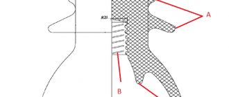
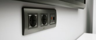
Let's start with the simplest thing, which should be present not only on sockets for computers, but in general on everything that uses electricity - grounding. For some unknown reason, most electricians do not like grounding and try in every possible way not to do it, even if all the conditions are created for this.
Let's start with what it is. Simply put, this is the third wire (in addition to phase and zero), coming to your outlet to a special grounding circuit (see Fig. 1) and going into the electrical panel (see Fig. 2) to a special terminal and only then into the ground.
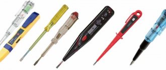
How to determine if you have grounding? In principle, you yourself can only see whether there is a grounding circuit in the socket, and whether the third core in the wire is connected there (it is usually yellow-green), but you can only check for sure using a tester (aka PIN ). Buying one for the sake of one socket is quite stupid, and therefore it is better to ask an electrician for this service if he wanders into your home 
But if you have a PIN, then you can do everything yourself. Here is the algorithm of actions:
- Insert the PIN into both holes in the socket, if the light comes on, then voltage is coming to the socket;
- Pull out one PIN probe and touch it to ground. If the light comes on, then you have grounding, and if not, follow the next step;
- Insert the probe back and pull out the second one, touch the ground again - if the light comes on, then there is a ground, otherwise there is no ground.
What is it for? If in an electrical appliance with a metal casing, a wire (phase) has come loose (burnt off, fallen off) and touched the body, then if there is no grounding, when you touch it, you may get an electric shock (deadly or not - depending on your luck), but if you have grounding, then the current from the detached the wires will go into the ground (literally). This will cause an overload (short-term overload) in the network, which will trip the circuit breaker (circuit breaker). This is how a simple wire can save your life
Things are even simpler with a computer. If you have a high-quality power supply (article about choosing it - The whole truth about the power supply. Stingy people pay twice), then the likelihood that some wire will come off and touch the case is very low. But when operating a computer, other problems related to electricity may arise: static charge (quite strong), breakdown through dust, and much more. All this can cause significant harm to your computer, and all these troubles can cause the system to freeze/crash, or the USB or network card to burn out. It is in order to remove excess charge and prevent these troubles that grounding is needed.
Where is the filter used and what to do if it is not there?
The fact is that in high-quality power supplies it must be installed directly on the board, and even more so on high-power power supplies, such as computer ones. But, unfortunately, your chargers for a smartphone, power supply from a laptop, electronic ballasts of fluorescent and LED lamps most often do not contain them. This is due to the fact that Chinese manufacturers are simplifying the circuits of their devices to reduce their cost. It often happens that there are places on the board for parts whose purpose is to filter interference, but they are simply not soldered and there are jumpers instead. Computer units are a separate issue; almost all of them have the same circuit, but the design is different, and the cheapest models do not have a filter.
You can reduce interference from your TV or other device that you want to protect and improve the properties of its power supply by adding such a filter to a regular power strip. You can assemble it yourself or extract it from a good, but unnecessary or faulty power supply unit.
Finally, we recommend watching a useful video on the topic:
A surge filter is a simple but useful device that will improve the quality of the power supply to your devices and reduce the harm caused to its frequency by the operation of switching power supplies, and the scope is quite wide - use it for any modern equipment. Its design allows even a novice radio amateur to repeat the circuit, and repairs are not difficult. The use of a surge protector is highly desirable for consumers of any kind.
It will be useful to read:
- Overvoltage in the network - what to do
- What are the types of interference in the electrical network?
- How to choose an uninterruptible power supply for your home
- What types of voltage stabilizers are there?
Published: 01/22/2018 Updated: 01/24/2019
Typical frequently asked questions from readers
How to find and eliminate the source of interference in an electrical circuit that makes it impossible to use powerline?
To figure out the cause of a bad signal, you need to analyze the operation of the powerline adapter on another line or check the devices already connected.
First, check the signal level on the router’s network; perhaps your router’s resources are not enough to redistribute the Internet between so many users. If the provided limit is sufficient for all rooms and receivers in them, check the operation of the lines over which powerline adapters transmit data. The next question is the type of line to which the powerline adapter is connected. The manufacturer does not recommend using extension cords for this, preferring fixed wiring. But, to test existing lines, I recommend that you temporarily use an extension cord; if the signal improves, it is likely that the reason is in the wiring. If not, check household electrical equipment that is the most powerful source of electromagnetic interference.
These include: air conditioners, washing machines, refrigerators, chargers for mobile phones, power supplies for electrical appliances.
If possible, the powerline adapter should be moved as far as possible from such devices so that they do not make adjustments to the quality of the transmitted signal. If this is not possible, connect the noise sources to the electrical circuit through a “surge filter”, which will help reduce the distortion introduced.
Another point that you should pay attention to is the permissible distance between powerline adapters. It must exceed the established norm, otherwise no tricks will help you achieve the proper signal quality.
Classification of interference in the electrical network
Interference occurring in the electrical network negatively affects the connected equipment. They can lead to serious malfunctions in a short period of time. Sudden voltage surges can be caused both by the influence of natural phenomena (lightning, magnetic fields), and by the quality of the line to the consumer or the equipment of the energy supply company.
Depending on the nature of the occurrence, interference can be of two types:
- high frequency (HF);
- pulsed.
High-frequency interference appears from electronic components of operating equipment connected to the network. For example, during the operation of a refrigerator, washing machine, and other equipment that has motors in its design. To a lesser extent from devices with switching power supplies: TV, tape recorder, computer, etc. RF interference is always present and it is impossible to completely remove it. Although this kind of interference exists, its negative impact is not great.
Pulse interference manifests itself in the form of noise, and can be either in the form of single pulses or their sequence. The parameters and shape of the pulses are usually chaotic; they arise due to sudden changes in current and voltage. These surges are caused by switching processes associated with the startup of powerful equipment or when a short circuit occurs, as well as magnetic fields.
There are several ways to deal with existing deviations in the operation of the electrical network. The most accessible way is to use voltage stabilizers or protective filters. The use of such devices in everyday life does not require alteration or modernization of the power line. The protected equipment is connected to them through a built-in socket, and they themselves are connected directly to a 220 V network through a plug.
How to protect home appliances from interference
Today, there are several effective ways to combat various physical abnormalities in the operation of the electrical network:
- Voltage regulator;
- uninterruptable power source;
- network filters.
A voltage stabilizer allows you to control the voltage level in the network and, if a sharp imbalance occurs, the device will stop supplying electricity to the consumer. The stabilizer itself is connected between the voltage source and the electricity consumer itself.
Stabilizer is an effective way to protect household appliances. The device stops supplying electricity to the consumer in the event of a power surge and resumes supply when the voltage returns to normal.
True, this method of dealing with interference is not always suitable as the main one. For example, when working with a computer, it is important for the user to ensure that all unsaved text data does not disappear. In this case, it is best to use a UPS - an uninterruptible power supply. The UPS includes a regular battery, which continues to keep the computer operational for some time after interference and subsequent power surges have occurred.
A cheaper way to make home appliances immune to interference is with surge protectors. They also do their job well and are used most often when connecting large household appliances: refrigerator, washing machine.
Measurement methods
Measuring noise in the network is carried out with special instruments. But if there are no such devices, then additional specific measures should be taken.
As a rule, the device that needs to measure interference in the electrical network will be powered from the same source that needs to be measured. If the wires are connected incorrectly, errors will occur when taking readings. The figure below shows the connection diagram of the device with which the measurement will be carried out:
An oscilloscope is also used to measure interference. If there is a storage tube, the device will be able to make a measurement. We talked about how to use an oscilloscope in a separate publication.
Now you know what causes interference in the electrical network and how to protect yourself from it. We hope the information provided was useful to you!
You probably don't know:
- Low voltage in the network - where to complain
- How to protect the cable from damage
- Errors when installing electrical wiring
Published: 02/03/2017 Updated: 11/07/2019
How and with what to measure interference
It is possible to measure interference in the electrical network and its direct impact using special instruments. The device is connected to a source where interference is observed. It is important to carry out the preparatory work correctly, which involves correctly connecting the device to the network. Otherwise, there will be an error in the readings, which will complicate the further course of action to combat interference.
All work can be done, for example, using an oscilloscope. The device is connected to the network and after some time the voltage and other characteristics are displayed on the display.
Interference classification
There are two types of interference in the electrical network: pulsed and high-frequency. The first ones occur when the device is turned on or off in the mains. They are dangerous because they can destroy all electronic equipment in the house in a short time. High-frequency interference always exists in the network, but is considered not as dangerous as pulsed interference.
Causes of the phenomenon:
- voltage fluctuations and deviations;
- impulse voltages;
- harmonics;
- frequency deviations;
- short voltage dips.
An electrical network in which interference is present may be subject to voltage deviations and fluctuations. You can learn more about what voltage surges are and how to protect yourself from them in our article.
The electrical network is also subject to pulse voltages. The reason may be natural phenomena in the form of a thunderstorm or switching operations that are carried out on the network.
An electrical network with multiple harmonics can be connected to a transformer through static frequency converters. The frequency and duration of harmonics will depend on the output frequency of the converter.
Frequency deviation occurs due to the fact that the power of the generators that produce electricity does not correspond to the consumed load. An electrical network that increases load power increases the frequency and speed of the generator.
If the electrical network receives an unexpected and sharp decrease in voltage, this means that a disturbance such as short voltage dips has occurred. The power grid restores normal operation after a certain time. This phenomenon occurs in power systems due to switching processes that are associated with the start and operation of high-power motors, and are also associated with short circuits.
Consumers must take into account the fact that it is impossible to eliminate or reduce the amount of interference generated by the operation of power systems to eliminate short circuits.
Automatic devices for protecting electrical networks
Currently, automatic electrical network protection devices
are the most reliable. The most commonly used types are:
- circuit breakers;
- residual current devices;
- differential automatic machines;
- Surge protection devices;
- stabilizers.
With the correct choice of such a device, guaranteed protection of the electrical network is ensured against malfunctions caused by the reasons indicated above. The choice of automatic electrical protection device must take into account its type, purpose, and rating.
Circuit breakers
Read about how to select the characteristics of circuit breakers
These devices are switching devices designed to turn on and off
current using manual control, as well as automatic shutdown of the current when it increases above a value exceeding the rating of the device.
In other words, a properly selected circuit breaker
must interrupt the line as soon as the current exceeds that permissible for the circuit in which it is installed.
The current may increase due to a short circuit or the inclusion of a powerful load. To protect a single-phase electrical network, a single-pole or two-pole circuit breaker is installed, and to protect a three-phase network, a three-pole circuit breaker is installed
. Very rarely, four-pole devices are used that can immediately disconnect all four (including the neutral or “zero”) conductors in a three-phase electrical network in the event of an emergency.
Thus, the task of the circuit breaker is to de-energize the circuit when overloads and short circuits occur, causing the conductor to overheat.
Residual current devices
Read all about residual current devices and their characteristics
Unlike circuit breakers, residual current devices
(RCD) are designed to protect electrical networks from leakage. It is always present in small quantities in any electrical circuit. But in dangerous values, leakage can occur for several reasons:
- malfunction of an electrical appliance due to breakdown of a phase conductor to the housing;
- moisture getting on the contacts for connecting wires;
- insufficient insulation properties in the wiring due to natural wear or mechanical damage.
The result of a leak may be injury to humans or pets, as well as fire of wire insulation.
The task of the RCD is to turn off the current supply within a short period of time when a leak is detected in the circuit. If this is done in time, the impact of electricity will be so small that any living organism will not feel it, and the flammable material will not have time to ignite.
However, if an overload or short circuit occurs in the network, the RCD will not work.
Differential machines
A differential circuit breaker combines an RCD and a circuit breaker in its design. Therefore, the correct name of the device is differential circuit breaker. It is capable of disconnecting the network supplying the electrical installation in the event of a current leak in it, and in the event of an overload or short circuit.
As a rule, a differential circuit breaker is installed on a separate circuit that supplies power to one powerful consumer. This could be, for example, an electric stove, an electric oven, an electric water heater, an air conditioner.
Surge protection devices
These devices protect networks from instantaneous surges in voltage and current. This can happen when there is a lightning strike, overlapping of overhead power lines, accidents in power supply networks, or switching on of equipment with high reactive power.
Surge voltage protection devices are installed directly in front of the consumer. The main condition for the successful operation of an SPD is the presence of high-quality grounding of the entire electrical installation. Currently, such devices are widely used in smart home equipment control systems for private homes.
Stabilizers
Stabilizers provide voltage equalization where any fluctuations in this characteristic are unacceptable. They protect complex electronic devices and equipment from failure. The main requirement for the stabilizer is to ensure equalization of the current at the maximum permissible load for a given time.
Stabilizers can protect the entire electrical installation, or they can be installed to protect just one device or electrical unit.
Main types of interference in the electrical network
There are a whole host of reasons that cause various types of interference. Any network can experience both pulsed and high-frequency interference. The first ones occur when turning the device on and off and are the most dangerous for household appliances. Physically, they represent a transient increase in voltage amplitude. A sharp voltage drop is fatal for many microcircuits that modern devices are equipped with.
As for high-frequency interference, it is worth noting that they are almost always observed in the network. It is not possible to completely get rid of them. You can observe RF interference during operation of a refrigerator, coffee maker and other appliances. They are transmitted not only by wire, but also over the air. However, they do not pose a big threat and have virtually no effect on the service life of home appliances.
Afterword
This is how it works somehow. Perhaps there are too many different parameters and buzzwords. Perhaps it is very superficial, not clear enough and not detailed enough for everyone.. But.. do not forget that taking precautions will help you keep your computer safe and sound. It is not necessary, after reading the article, to immediately do everything that is recommended in it. But, at a minimum, think about the question and, at least in your mind, approximately select what is suitable for you and what is worth, as they say, “bothering.”
PS Thanks to a former member of the Proxy team for the existence of this article
Network filters
The so-called surge protector is often just a splitter/extension cord, the protective functions of which are either virtually absent or minimal and can only protect against overload or short circuit.
However, hidden among the “decoys” are real network filters that, using an LC circuit, filter high-frequency interference in the network. The cost of such devices is naturally higher, but for some types of equipment, full filtration is necessary. Devices with an LC circuit have the “EM/RF Noise Reduction” feature
If you need this option, pay attention to it
High frequency interference
Surge filters ensure the safety of your equipment. They include a high-frequency interference filter that protects electrical appliances from various malfunctions. They also have a pulse noise filter (protection against pulse noise): thus, two problems are solved at once.
Classic network filters consist of a protection unit containing varistors, and their second component is a capacitive or inductive-capacitive filter. The capacitor together with the inductor is a high-frequency noise filter. And varistors create the most reliable impulse noise filter existing today.
Varistors (semiconductor resistance) play the role of “scissors” that “cut” high-frequency interference, voltage at the level of 800-1200 volts and thereby preserve the equipment connected to the filter sockets. Their purpose is protection against impulse noise. When the pulse is very powerful, the varistors may be destroyed, but the equipment will not be damaged. Pulse interference will not pose a threat to your electrical appliances if they are connected to the network through a surge protector.
A capacitive or LC filter, consisting of a capacitor (capacitive filter) or a capacitor and an inductor (LC filter), protects against high-frequency interference, reducing its harmful effects. The degree of reduction depends on the capacitance value of the capacitor and the inductance of the coil.
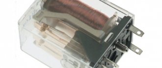
Voltage relay
Voltage relays, also called breaker relays, open electrical circuits during voltage surges. After turning off the power, the relay checks the voltage status at short intervals and, if the values are normal, resumes the current supply.
Some models are equipped with regulators that allow you to configure the relay for different devices, setting the upper and lower limits of the differences for shutdown, as well as the time of subsequent activation. There are models of relay interrupters both for mounting in an electrical panel and for separate installation in an outlet.