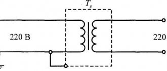
Single-phase transformer
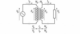
A voltage transformer will accordingly be called a step-up if the voltage at the output from the secondary winding is higher than in the primary, and a step-down if the voltage in the secondary winding is lower than in the primary. The figure below shows the operating diagram of the transformer:
Transformer circuit diagram
Red (in the figure below) indicates the primary winding, blue the secondary winding, and also shows the transformer core, assembled from special electrical steel plates. The letters U1 indicate the voltage of the primary winding. The letters I1 indicate the current of the primary winding. U2 indicates the voltage on the secondary winding, I2 indicates the current in the secondary. In a transformer, two or more windings are inductively coupled. Transformers can also be used for galvanic isolation of circuits.
Transformer operating principle
Transformer operating principle
When voltage is applied to the primary winding, a self-inductive emf is induced in it. The magnetic field lines penetrate not only the coil that induces current, but also the second coil located on the same core (secondary winding) and also induces a self-inductive emf in it. The ratio of the number of turns of the primary winding to the secondary is called the Transformation Ratio. It is written like this:
- U1 = primary voltage.
- U2 = secondary voltage.
- w1 = number of turns of the primary winding.
- w2 = number of turns of the secondary winding.
- kt = transformation ratio.
Transformation coefficient - formula
If the transformation ratio is less than one, then the transformer is step-up, if it is more than one, then the transformer is step-down. Let's look at a small example: w1 the number of turns of the primary winding is equal to 300, w2 the number of turns of the secondary winding is 20. Divide 300 by 20, we get 15. The number is greater than one, which means the transformer is a step-down. Let's say we wound a transformer from 220 volts to a lower voltage, and now we need to calculate what the voltage will be on the secondary winding. We substitute the numbers: U2 = U1\ct = 220\15 = 14.66 volts. The output voltage from the secondary winding will be 14.66 volts.
Design
The transformer design assumes the presence of one or more individual coils (tape or wire), located under a single magnetic flux, wound on a core made of a ferromagnet.
The most important structural parts are as follows:
- winding;
- frame;
- magnetic circuit (core);
- cooling system;
- insulation system;
- additional parts necessary for protective purposes, for installation, to provide access to the output parts.
In devices you can most often see two types of winding: the primary, which receives electric current from an external power source, and the secondary, from which the voltage is removed.
The core provides improved return contact of the windings and has reduced magnetic flux resistance.
Some types of devices operating at ultrahigh and high frequencies are produced without a core.
The production of devices is established in three basic winding concepts:
- armored;
- toroidal;
- core.
The design of core transformers involves winding the winding onto the core strictly horizontally. In armor-type devices it is enclosed in a magnetic circuit and placed horizontally or vertically.
Reliability, operational features, design and principle of operation of the transformer are taken without any influence from the principle of its manufacture.
Transformers on diagrams
The transformer is designated on the schematic diagrams as follows:
Transformer designation on diagrams
The following figure shows a transformer with multiple secondary windings:
Transformer with two secondary windings
The number “1” indicates the primary winding (on the left), numbers 2 and 3 indicate the secondary windings (on the right).
Decoding the main parameters
The diversity in design and wide range of parameters of transformers have led to the need for their marking according to a special standard. Without having a technical description at hand, the characteristics of the device can be determined by the information printed on its surface, expressed in an alphanumeric code.
The marking of power transformers contains 4 blocks.
Let's decipher the first three blocks:
Decoding of markings: 1,2,3 blocks
- The first letter "A" is attached behind the autotransformers. In its absence, the letters “T” and “O” correspond to three-phase and single-phase transformers.
- The further presence of the letter “P” informs about devices with split winding.
- The third letter means cooling; the oil natural cooling system is assigned the letter “M”. Natural air cooling is marked with the letter “C”, oil cooling with forced airflow is designated “D”, with forced oil circulation – “C”. The combination “DC” indicates the presence of forced oil circulation with simultaneous air blowing.
- The letter “T” marks three-winding converters.
- The last sign characterizes the features of the transformer:
- “N” – on-load tap-changer (voltage regulation under load);
- space – switching without excitation;
- “G” – lightning protected.
Welding transformers
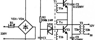
There are special welding transformers.
Welding transformer
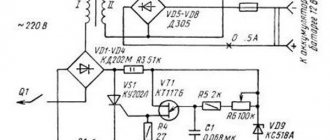
The welding transformer is designed for electric arc welding; it works as a step-down transformer, reducing the voltage on the secondary winding to the required value for welding. The voltage of the secondary winding is no more than 80 Volts. Welding transformers are designed for short-term short circuits of the output of the secondary winding, in which an electric arc is formed, and the transformer does not fail, unlike a power transformer.
Areas of different technologies
For example, electric furnace transformers are used to power electrothermal installations. Such transformers usually operate at a frequency of 50 Hz, and their power can reach tens of thousands of kilovolt-amperes at voltages up to 10 kV.
In the field of electric welding, welding transformers are widely used, the power of which is much less than that of electric furnaces.
As a case of a single application, the Tesla transformer, which is used to create special effects in the show industry.
To supply power to various electrical circuits of radio and television equipment, automation and telemechanics, communication products, electrical household appliances; as well as for separating and (or) matching the voltages of the circuits of various elements of the above devices, etc.
These transformers are usually low-power (volt-ampere to several kilovolt-ampere). They can have two or more windings, operate at low voltages, mainly at a frequency of 50 Hz, but much less often at higher frequencies (up to tens of kilohertz). The operating conditions of the above transformers can often be specific, which can cause increased requirements in manufacturing and design.
Power transformers
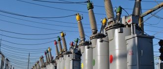
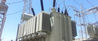
Electricity is transmitted through high-voltage lines from generators, where it is generated to high-voltage consumer substations, in order to reduce losses, at high voltages of 35-110 kilovolts and above. Before we can use this energy, its voltage must be lowered to 380 volts, which is supplied to electrical panels located in the basements of apartment buildings. Three-phase transformers are usually designed for higher power. In electrical networks at transformer substations there are transformers that reduce the voltage from 35 or 110 kilovolts to 6 or 10 kilovolts; probably everyone has seen such transformers the size of a small house:
Photo high voltage transformer
Transformers from 6-10 kilovolts to 380 volts are located near consumers. Such transformers are located at transformer substations located in many courtyards. They are smaller in size, but together with HVs (load switches) that are placed in front of the transformer and input circuit breakers and feeders, they can occupy a two-story building.
Transformer 6 kilovolt
Three-phase transformers have windings that are connected differently than single-phase transformers. They can be connected into a star, a triangle and a star with the neutral removed. The following figure shows, as an example, one of the connection diagrams for the high voltage and low voltage windings of a three-phase transformer:
An example of connecting the windings of a power transformer
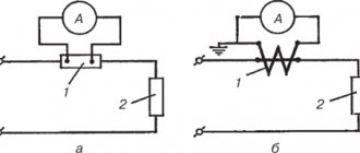
Transformers exist not only for voltage, but also for current. Such transformers are used to safely measure current at high voltage. Current transformers are designated in the diagrams as follows:
Current transformer diagram image
The photo below shows exactly these current transformers:
Current transformer - photo
There are also so-called autotransformers. In these transformers, the windings have not only magnetic coupling, but also electrical coupling. This is how a laboratory autotransformer (LATR) is designated in the diagrams:
Laboratory autotransformer - diagram image
LATR is used in such a way that by turning on part of the winding, using a regulator, you can obtain different output voltages. A photograph of a laboratory autotransformer can be seen below:
Photo LATR
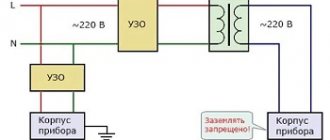
In electrical engineering, there are schemes for safely switching on LATR with galvanic isolation using a transformer:
Safe LATR image on the diagram
A matching transformer is used to match the resistance of different parts of the circuit. Instrument transformers are also used to measure very large or very small voltages and currents.
A little history
Thanks to the English physicist Michael Faraday, in 1831, humanity became acquainted with electromagnetic induction. The great scientist was not destined to become the inventor of the transformer, since his experiments involved direct current. The prototype of the device can be considered the unusual induction coil of the Frenchman G. Ruhmkorff, which was presented to the scientific world in 1848.
In 1876, Russian electrical engineer P. N. Yablochkov patented an alternating current transformer with an open core. The device owes its modern appearance to the English brothers Hopkinson, as well as the Romanians K. Tsiperanovsky and O. Blati. With their help, the design acquired a closed magnetic circuit and has preserved the circuit to this day.
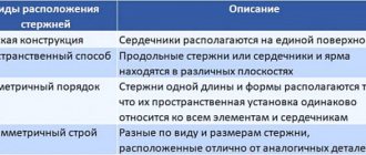
Types of magnetic cores
Safety precautions
During operation, certain rules must be observed:
- if cracks appear on the case, noise or vibration, the autotransformer is immediately turned off;
- It is prohibited to leave equipment for which continuous monitoring is provided unattended;
- you cannot connect a motor whose power is more than 70% greater than the power of the autotransformer;
- These devices must not be used openly, covered, covered with ventilation openings, or placed on them with other equipment or objects.
When carrying out repairs on an autotransformer or the device it is part of, it is necessary to disconnect it from the power supply.