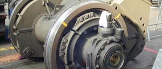
The reliability, uninterrupted operation and ease of maintenance of a three-phase asynchronous electric motor have been tested by time, millions of users around the world and do not require proof. Moreover, it is the most widespread, accessible and cheapest today. However, not everyone has a 380 V current source. Therefore, let’s look at what it means to connect a three-phase electric motor to a 220 V network, what methods exist for this and what are their main features.
Three-phase electric motor Source ytimg.com
Winding connection options
An asynchronous three-phase electric motor has three windings - for each phase separately - going into the stator slots. However, for the generation of electromotive force and, as a result, rotation of the rotor, they must be connected to each other. It is important to know the connection option for a specific motor. Since this will help you choose the right scheme for connecting it to the 220V network.
Each of the three windings corresponds to its own phase and has both a beginning and an end. In this case, the inputs and outputs are designated by the corresponding letters and numbers:
Range of engines produced during the Soviet Union:
- The first phase is C1-C4.
- Second phase C2-C5.
- Third phase C3-C6.
Designations of modern engines:
- First phase U1-U2.
- Second phase V1-V2.
- Third phase W1-W2.
Connecting the winding of a three-phase motor Source autogear.ru
There are two main circuits for connecting the windings in the type of motor under consideration:
- Star.
All winding outputs are connected to one point, and the inputs, respectively, to the phases. The schematic representation of this method looks like a star. With this method, a 220V phase is applied to each individual core, and a linear 380V is applied to two consecutive cores.
The main advantage of this scheme is the application of linear current to two wires simultaneously, which significantly reduces inrush currents and allows the rotor to perform a soft start. The downside is lower power due to weak currents in the winding.
- Triangle.
The input of the previous winding is connected to the output of the next one - and so on in a circle. As a result, the diagram resembles a triangle. At a linear voltage of 380V, the currents in the winding will reach a significantly higher value than in the above option. This will make it possible for the motor to exert a significantly greater amount of force. The disadvantage of the circuit is that stronger inrush currents can lead to network overload.
Triangle diagram Source ytimg.com
Good to know! To obtain the advantages of the first and avoid the disadvantages of the second circuit, the connection of the 380 V electric motor and its subsequent acceleration is carried out on the “star”, and then it is automatically switched to the “delta”.
Correct selection of capacitors
The selection of capacitors must be made as follows:
- The power of this device should be 1.5 times less than that of the electric motor (otherwise it is fraught with voltage surges when turned on and off, which leads to burnout of the capacitor);
- It is better to use metal-paper capacitors or, as a last resort, electrolytic capacitors soldered to diodes;
- Electrolytic capacitors must be installed in some kind of housing. If they fail, they explode and fly in different directions.
If you need diagrams for connecting a three-phase electric motor to a 220V network, you can download them for free on the website of the manufacturer of modern equipment - Lot-service (at the end of the page).
Definition of connection diagram
Before choosing one or another scheme for connecting a motor to 220 V, it is necessary to determine what the connection diagram for its winding is and at what rating it can generally be operated. To do this you need:
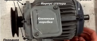
- Find and study the technical table on the engine. characteristics .
The information field contains all the important information - designation of the type of connection ∆ - triangle or star - Y , power, number of revolutions, voltage (220 or 380, or 220/380) and the possibility of connecting according to a specific circuit.
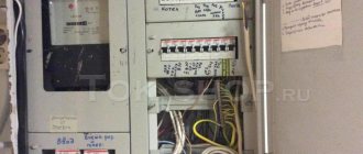
- Open the terminal box and verify in practice that the assembled circuit is correct.
The beginning and end of each winding is signed in accordance with the above alphanumeric nomenclature. The user remains to study the connection diagram using jumpers: according to what scheme the connection is made - star or triangle.
Note! If the nameplate (table with information) indicates the Y and only 380V, then when it is connected in a triangle, the winding will burn out. Only professional electricians can upgrade such a 220V motor. Therefore, there is no reason to modify it, especially since today there are many copies that can operate alternatively - both 220 and 380 volts.
Opening the terminal box Source pikabu.ru
See also: Catalog of companies that specialize in electrical work
Typical starting schemes for synchronous electric motors
Today, the use of synchronous motors has become widespread in the production of equipment operating at a constant speed, which is used in various fields of human activity. In this regard, there are several ways to start synchronous electric motors, the most common options of which will be presented below.
Methods for starting a synchronous electric motor
The methods for starting a synchronous electric motor are quite complex, this is one of the main disadvantages of electric motors of this type. Starting of synchronous electric motors is carried out either through the influence of an auxiliary starting motor, or using asynchronous starting. Let's consider each of the methods separately.
Asynchronous start of a synchronous electric motor
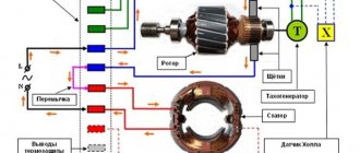
Asynchronous starting of a synchronous electric motor involves the location of an additional short-circuited winding in the pole pieces of the rotor poles. This is necessary to ensure that during start-up the excessively large EMF generated in the winding (1) is removed, which is possible due to the closure of the switch (2) to connection (3). Due to the fact that the magnetic field resulting from the switching on of the three-phase network voltage in the stator winding (4) crosses the short-circuited winding (starting winding) located in the rotor pole pieces, currents are induced.
The action of these currents, in combination with the rotating field of the stator, causes the rotor to rotate, which gradually gains speed. Having reached 95-97% of the number of revolutions, the switch (2) of the rotor goes into a state that forces the rotor winding to turn on the DC voltage network.
Asynchronous starting of a synchronous electric motor is not without drawbacks, or rather, a drawback, which is a large starting current, which can exceed the operating current by 7 times. Such a high value of the starting current causes a voltage drop in the network, which negatively affects the functioning of other energy consumers. One of the most common solutions to the mentioned disadvantage is the use of an autotransformer to reduce the voltage, as well as the use of thyristor exciters to start synchronous electric motors, which are characterized by high efficiency. It is the high value of efficiency. largely determined the choice of thyristor exciters as sets for most of the large-sized synchronous electric motors produced. In addition, the use of thyristor exciters makes it possible to automate the process of excitation supply to a synchronous motor. Automation can be implemented in 2 ways: excitation of a synchronous motor as a function of speed and excitation of a synchronous motor as a function of current. In this case, control of the excitation supply to the synchronous motor as a function of current is carried out using a current relay.
At the moment, it is the asynchronous starting of synchronous motors that has become most widespread, since it is quite simple to implement, and it works extremely reliably.
Starting a synchronous motor using an auxiliary motor
Starting a synchronous motor with the help of an auxiliary motor involves starting a synchronous electric motor thanks to the operation of another motor, the operation of which allows the rotor of the synchronous motor to turn its poles, carrying out further rotation completely independently. In order for the start to occur, it is necessary to create conditions under which the number of pole pairs of an asynchronous motor would be less than the number of pole pairs of a synchronous motor. The procedure for starting a synchronous motor involves turning on the switch (3), starting the auxiliary asynchronous motor (2), which rotates the rotor of the synchronous motor (1) to a speed that corresponds to the speed of the stator field. Next, the rotor poles are turned on after turning on the switch (4). When a synchronous motor is connected to a three-phase current network, synchronization is required by a rheostat (5). The rheostat organizes excitation, which makes it possible to set the voltage of the stator winding, determined by the voltmeter V, equal to the voltage in the network, which is indicated by the voltmeter V1.
When the switch is open, the lamps (6), located parallel to the switch blades (7), will flash. As the rotation speed of the auxiliary induction motor changes, the lamps will gradually begin to blink less and less until they all go out at once. This is a signal that it is time to connect the synchronous motor to the three-phase current network using a switch (7). Since the motor rotor can continue to rotate without assistance, it is time to disconnect the auxiliary motor (2) from the network using the switch (3).
This is a complex procedure, which is the main disadvantage of this version of an asynchronous electric motor, which determines the extremely rare cases of its practical implementation. To place an order, call the managers of the Kabel.RF® company by phone or send a request by email indicating the required electric motor model, purposes and operating conditions. The manager will help you choose the right brand, taking into account your wishes and needs.
Connection methods for 220V
To connect a three-phase asynchronous electric motor to a 220-volt network, there are several proven methods:
- With capacitor.
- Without capacitor.
- With reverse.
- Combined star-delta circuit.
Let's look at them in more detail.
Important! When connecting a 380-volt electric motor to a 220-volt network, you need to be prepared to reduce its power to 70% of the factory value. However, in everyday conditions this is quite acceptable and will not affect the performance in any way.
Connecting a 380 V motor to 220 V Source ytimg.com
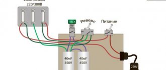
With capacitor
The most popular and affordable way to initiate 380 volt motors from a 220 V network is a circuit using a capacitor. Its role is to create a phase shift in the windings relative to each other in order to form a rotating magnetic field. If there are three phases, this phenomenon occurs by itself - only one will not force the rotor to rotate. Therefore, the optimal method for connecting an electric motor with 4 wires on one phase is to use a starting winding, in addition to the main winding, in 220V electric motors.
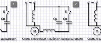
For the 380 V modification, two connection options with a capacitor are possible:
- With working capacitor Cp .
- And parallel connected working Cp and starting capacitor Sp .
In the second case, the engine starts more smoothly and safely. Sp module turns on for a short period of time and turns off as the rotor reaches the required speed. The choice of starting option is largely determined by the degree of rotor load during starting. So, if the start occurs without force, only Cp , and if under load, without free rotation, the presence of Cn .
Connecting a motor with capacitors Source blogspot.com
How to calculate capacity
The capacity of the capacitor, which is installed in the connection circuit of a three-phase electric motor connected to a 220V network, depends on the circuit itself. There are special formulas for this.
Star connection:
Cр = 2800 I/U, where Ср is capacitance, I is current, U is voltage. If a triangle connection is made, then the same formula is used, only the coefficient of 2800 changes to 4800.
I would like to draw your attention to the fact that the current strength (I) is not indicated on the motor tag, so it will need to be calculated using this formula:
I = P/(1.73 U n cosph), where P is the power of the electric motor, n is the efficiency of the unit, cosph is the power factor, 1.73 is a correction factor, it characterizes the relationship between two types of currents: phase and linear.
Since most often the connection of a three-phase motor to a single-phase 220V network is made in a triangle, the capacitance of the capacitor (working) can be calculated using a simpler formula:
C = 70 Pn, here Pn is the rated power of the unit, measured in kilowatts and indicated on the device tag. If you look at this formula, you can understand that there is a fairly simple relationship: 7 uF per 100 W. For example, if a 1 kW motor is installed, then it requires a 70 µF capacitor.
How to determine whether the capacitor is correctly selected? This can only be checked in operating mode.
- If during operation the motor overheats, it means that the capacity of the device is greater than required.
- Low engine power means the capacity is underestimated.
Even calculations can lead to the wrong choice, because the operating conditions of the motor will affect its operation. Therefore, it is recommended to start the selection with low values, and, if necessary, increase the indicators to the required (nominal) values.
As for the starting capacity, what is first taken into account is what starting torque is needed to start the electric motor. I would like to draw your attention to the fact that the starting capacitance and the capacitance of the starting capacitor are not the same thing. The first value is the sum of the capacitances of the working and starting capacitors.
Attention! The capacity of the starting capacitor should be three times greater than the capacity of the working capacitor. At the same time, experts advise using several with small capacity instead of one large device. In addition, the launchers only work for a short time, so cheap models can be installed in their place.
As workers, you can use paper, metallized or film analogues. In this case, it is necessary to take into account the fact that the permissible voltage should be one and a half times the nominal voltage. As you can see, choosing the exact capacitor for an electric motor is quite difficult. Even calculation is an imprecise process.
Related posts:
Most owners of private garages or workshops are faced with the issue of connecting a 380V electric motor to 220V via a capacitor or other methods. Some types of equipment that may be privately owned, such as concrete mixers, grinders or woodworking machines, consume a lot of power.
An asynchronous three-phase motor can provide it, but its main problem is that it is designed to connect to a 380V power network, which is absent or severely limited in most private households. We will consider options for getting out of the current 380/220 situation below.
Useful tips
Some useful tips on how to connect a 3-wire motor to avoid problems during operation:
- Before starting work, it is recommended to test the engine at idle, if it is functioning properly, then under load.
- If the case becomes very hot, even without load, it is necessary to reduce the capacity of the working capacitor.
- If after starting the motor just hums, but does not rotate the shaft, then you can set it to start manually - by turning the shaft. Next, you can increase the capacity of the starting capacitor.
- When stopping the engine under operating load, the capacity of the working capacitor should be increased.
Helpful information! It is possible to correctly calculate the capacitance of the capacitor only taking into account the power rating of the motor. If there is underload, overheating will occur and the capacity will need to be reduced.
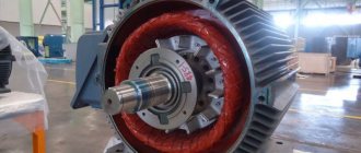
Synchronous motor device
The design of a synchronous motor consists of two main parts - the stator and the rotor. The stator is the stationary part of the unit, and the rotor is the movable part. The armature consists of one or more alternating current windings. When the motor is running, the currents entering the armature lead to rotation of the magnetic field, which intersects with the field of the inductor and converts energy. The anchor field has another name - the anchor reaction field. In a generator, such a field is created using an inductor.
The inductor contains DC electromagnets called poles. In all synchronous electric motors, inductors come in two designs - salient-pole and non-salient-pole, differing in the arrangement of the poles. The stator design includes a housing and a core, which includes two- and three-phase windings. The windings themselves can be distributed or concentrated.
To reduce magnetic resistance and improve the passage of magnetic flux, ferromagnetic cores are used, located in the rotor and stator, for the manufacture of which electrical steel is used. It has interesting properties, such as increased silicon content, in order to increase its electrical resistance and reduce eddy currents.
Each synchronous electric motor has an important parameter - electromagnetic torque. It occurs when the magnetic flux of the rotor begins to interact with the rotating magnetic field. This field is formed under the influence of three-phase current flowing through the armature winding.
In idle mode, the axes of the magnetic fields of the rotor and stator coincide. Therefore, the electromagnetic forces arising between their poles take a radial direction and the value of the electromagnetic moment of the unit becomes equal to zero. When the device switches to motor mode, the rotor begins to be affected by external load torque applied to the shaft. As a result, the rotor is displaced by a certain angle against the direction of rotation.
Such electromagnetic interaction between the rotor and stator leads to the creation of electromagnetic forces directed in the direction of rotation. Thus, the action of the rotating electromagnetic torque tends to overcome the action of the external torque. The maximum value of the electromagnetic torque forms an angle of 90 degrees when the rotor poles are located between the axes of the stator poles.
If the load torque applied to the motor shaft exceeds the maximum electromagnetic torque, the motor will stop under the influence of an external torque. Because of this, in a stationary motor, a very high current will flow through the armature winding. This mode is an emergency; it represents a loss of synchronism and should not be allowed in practice.
Briefly about the main thing
You can connect a 380 to 220 volt electric motor in 4 main ways:
- With capacitor.
- Without capacitor.
- With reverse.
- Star-delta design.
Before starting connection work, it is necessary to determine and verify how the winding is connected in the terminal box, and also find out the necessary characteristics from the technical table. You can perform electrical work if you have experience, but it is better to entrust it to professionals with the appropriate permit.
How to connect a single-phase asynchronous motor
Any asynchronous electric motor, designed for power from a single-phase 220 V network, has two windings - starting and working. A cylindrical aluminum blank is used as a “collector”, which is mounted on a shaft. You can even note that the cylinder on the rotor is, in fact, a short-circuited winding. There are many schemes for turning on an asynchronous motor, but few are used in practice:
- Using a ballast resistor connected to the start winding.
- With a capacitor on the start winding.
- Using a push-button or relay starter, a starting capacitor connected to the start winding circuit.
Very often, a combination of a push-button or relay starter, as well as a constantly switched on operating capacitor, is used. Instead of a relay, an electronic key based on a thyristor is very often used. Using this switch, a single-phase electric motor is connected with an additional group of capacitors.