There are no specific figures in the PUE.
There is information regarding the length of the weld seam taking into account round ground electrodes and the length of the weld seam on the welded metal strips of the earth electrode.
If this is a round ground electrode (round reinforcing steel, as a rule), then the length of the weld is at least six of its diameters, for example, the diameter of the ground electrode is 10 mm, which means the length of the weld is at least 60 mm, more is possible, but there is no point, It's enough.
If we are talking about a flat grounding conductor, then the length of the weld is no less than the width of that same strip.
For example, a 4x40 steel strip is used (4 mm is the thickness, 40 mm is the width of the strip), which means the length of the weld is 40 mm or more, but not less.
Also in the PUE there are requirements for the diameter of grounding conductors (if they are round) for the coating of welding seams.
Welded seams are coated (painted after cleaning from scale) with a special bitumen varnish,
Source www.remotvet.ru
Grounding electrical installations in industrial and residential premises is a prerequisite. Together with automatic shut-off devices, it reduces the likelihood of fires due to short circuits and injuries to people. We will tell you in the article what the main grounding bus is, where and when it is used.
1.7.139
Connections and connections of grounding, protective conductors and conductors of the equalization and potential equalization system must be reliable and ensure continuity of the electrical circuit. It is recommended to make connections of steel conductors by welding. It is allowed to connect grounding and neutral protective conductors in indoor and outdoor installations without aggressive environments in other ways that meet the requirements of GOST 10434 “Electrical contact connections. General technical requirements" for class 2 connections.
Connections must be protected from corrosion and mechanical damage.
For bolted connections, provisions must be made to prevent contact loosening.
Installation procedure for protective grounding
Protective grounding is a system of intentionally connecting iron parts of an electrical installation to the ground in order to increase the safety of its operation. Metal components of the structure should not be under voltage.
- installation of grounding conductors;
- laying of grounding conductor parts;
- connection of grounding conductors - between themselves and electrical equipment.
Vertical steel corner ground electrodes and rejected pipes are immersed in the ground and fixed by driving or pressing. Round steel parts are pressed or screwed into the ground according to the sign of the grounding location. To perform the work, special devices are used, machines - drills, copra, PZD-12. Most often, electric deepeners with a standard gearbox and drill are used to design the system. This helps to reduce the rotation speed to less than 100 rpm and increase the torque on the screw-in electrode. A drill tip is welded to the end of the electrode, which ensures normal immersion of the working part and loosens the soil. The factory electrode looks like a strip of 4x40 mm or other sizes. The grounding strip is pointed at the end and has a helical bend. Other types of electrode tips are also used; grounding clamps are used for fixation.
1.7.142
Connections of grounding and neutral protective conductors and potential equalization conductors to open conductive parts must be made using bolted connections or welding.
Connections to equipment that is subject to frequent disassembly or installed on moving parts or parts subject to shock and vibration must be made using flexible conductors.
Connections of protective conductors of electrical wiring and overhead lines should be made using the same methods as connections of phase conductors.
When using natural grounding conductors for grounding electrical installations and third-party conductive parts as protective conductors and potential equalization conductors, contact connections should be made using the methods provided for by GOST 12.1.030 “SSBT. Electrical safety. Protective grounding, grounding"
What is a grounding bus and how to install it
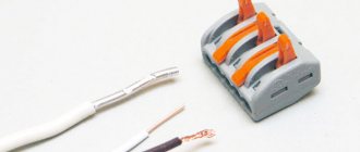
Most houses are equipped with old electrical transmission systems - that is, without grounding conductors. Such schemes are outdated and do not provide the proper level of security - when a large number of devices are connected to the network, the wiring may short out. The main tasks of the system are to turn off the mains voltage in case of current leaks and to create optimal conditions for the operation of household appliances. Some devices, in addition to having a grounding contact in the socket, require direct connection to a special bus using clamps. There are special clamps for this.
1.7.143
Places and methods of connecting grounding conductors to extended natural grounding conductors (for example, pipelines) must be selected such that when disconnecting the grounding conductors for repair work, the expected touch voltages and the calculated resistance values of the grounding device do not exceed safe values.
Shunting of water meters, valves, etc. should be carried out using a conductor of the appropriate cross-section, depending on whether it is used as a protective conductor of the potential equalization system, a neutral protective conductor or a protective grounding conductor.
What are the PUE grounding weld length standards?
There is information regarding the length of the weld seam taking into account round ground electrodes and the length of the weld seam on the welded metal strips of the earth electrode.
If this is a round ground electrode (round reinforcing steel, as a rule), then the length of the weld is at least six of its diameters, for example, the diameter of the ground electrode is 10 mm, which means the length of the weld is at least 60 mm, more is possible, but there is no point, It's enough.
If we are talking about a flat grounding conductor, then the length of the weld is no less than the width of that same strip.
For example, a 4x40 steel strip is used (4 mm is the thickness, 40 mm is the width of the strip), which means the length of the weld is 40 mm or more, but not less.
Also in the PUE there are requirements for the diameter of grounding conductors (if they are round) for the coating of welding seams.
Welded seams are coated (painted after cleaning from scale) with a special bitumen varnish,
1.7.145
It is not allowed to connect switching devices in PE
- and
PEN
conductors, with the exception of cases of power supply to electrical receivers using plug connectors.
It is also allowed to simultaneously disconnect all conductors at the input to electrical installations of individual residential, country and garden houses and similar objects fed by single-phase branches from overhead lines. In this case, the division of PEN
- conductor to
PE
- and - conductors must be done before the input protective switching device.
Lightning protection circuit
A lightning protection circuit is a comprehensive system for protecting an object from direct lightning strikes: lightning rod, down conductor, grounding. The classic scheme, proposed by Benjamin Franklin back in 1752, underlies all modern lightning protection systems. Proven technology combined with the latest equipment, professional design and installation provide almost one hundred percent protection against lightning damage!
Lightning protection circuit for buildings and structures
Lightning rods
There are 3 types of lightning rods:
In addition to classical solutions, active lightning rods are used. The devices ionize the air and provoke a lightning strike. Thanks to this, it is possible to reduce the number of lightning rods and the overall height of the lightning protection circuit.
An aluminum or steel conductor, the main task of which is to transmit current from the lightning rod to the ground electrode. As a rule, external down conductors are installed on buildings, but in some cases, according to the RD instructions, the use of building structures, for example, reinforcement in reinforced concrete blocks, is allowed. However, this is unacceptable in the presence of highly sensitive electronics: the electromagnetic field created during the passage of a discharge can damage the equipment.
1.7.146
If the protective conductors and/or potential equalization conductors can be disconnected using the same plug connector as the corresponding phase conductors, the socket and plug of the plug connector must have special protective contacts for connecting the protective conductors or potential equalization conductors to them.
If the body of the socket outlet is made of metal, it must be connected to the protective contact of that socket.
We will talk about artificial grounding in the TN system.
The first is connecting the circuit to the wrong point in the electrical installation where it should be connected. For example, the ground loop is connected directly to a washing machine or some machine tool.
In fact, the circuit must be connected to the main ground bus.
The second is to use, instead of a circuit, water supply, gas supply, heating pipes, or some other incomprehensible metal structures that people think could be a grounding circuit. Such structures may not always have a grounding loop.
Third, there is no connection between the 0 conductor and the grounding device. This also includes the installation of separate circuit breakers in the 0 conductor, which can turn off and the connection between the grounding device and the neutral conductor will be lost and there will no longer be protective grounding.
Fourth - the use of all kinds of objects buried in the ground as grounding devices; buckets, fittings, metal fences. Used as a worker ground 0. A metal fence around a house does not make a good loop.
Parts of the structure
For a more precise understanding of the essence of the requirements, it should be taken into account that a typical lightning protection design consists of the following main parts:
lightning rod mounted at the highest point of the object;
- a special tape conductor used as a connector of the discharge receiver with a grounding device (GD);
- the ground electrode itself, which ensures the discharge current flows into the ground.
Thus, each of the constituent elements of lightning protection performs its own, well-defined function that meets the requirements of current regulations, in particular PUE.
Copper
Along with galvanized strips, grounding strips with copper coating are widely used in practice. Copper is less electrochemically active than steel and zinc. Therefore, it lasts longer and can be used in more difficult conditions.
Copper-bonded grounding conductors have good ductility. They are supplied in unmeasured lengths, which is convenient for laying grounding loops. Copper strip is also used for the internal circuit as a main conductor used to connect equipment to it. The disadvantage of copper-plated grounding strips is their high price.
Installation location
The main busbar can be placed inside the input device of electrical installations. If installed separately, the busbar should be located in a conveniently accessible location.
If the product will be installed in areas accessible only to qualified personnel, an open location should be selected. If there is a risk of access by unauthorized people, the grounding bus should be placed in a protective shell - a cabinet, box, box with a key. There must be a grounding designation on the shell body, as well as a table with the technical characteristics of the product.
Self-production
After preparing all the necessary materials and choosing a suitable place for arranging the grounding, you can proceed to the direct operations of assembling the grounding loop. At the preparatory stage, pipe or other profile sections are cut, the size of which is chosen to be 20-30 cm larger than the calculated one (this is necessary to compensate for the bending of the top of the workpiece when it is driven into the ground).
Simultaneously with the preparation of point pin grounding conductors, the stage of excavation begins, consisting of the preparation of grooves with beveled edges (to better retain the soil from shedding).
The order of operations performed during excavation work is as follows:
- First, the site for the future ground loop is prepared (cleared) and its markings are made;
- Then, using the already applied markings, grooves are dug with a depth of 70-80 cm and a width of about 50 cm (the depth is chosen to minimize corrosion of metal bonds);
- After this, the pins, cut to length, are driven in at the designated points so that about 20 cm protrude above the surface (see photo below);
Arrangement of a grounding loop
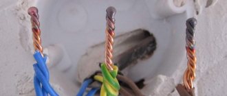
- Upon completion of the installation of all vertical elements, their upper parts are cut off, and the contact pads are thoroughly cleaned, after which metal connections are welded to them;
- After all welding seams have cooled, they are cleaned with a grinder and a grinding disc, and then painted with a special tar-based protective paint;
Note! Only areas of welded joints that are most susceptible to corrosion are painted.
- Next, from the short-circuit point closest to the residential building, a ditch is dug to the same depth that was dug under the metal connections (its width may be slightly smaller, since the connecting strip is made solid and does not require welding);
- Then a strip of metal with a standard size of at least 25x4 mm is laid in the prepared trench, which is subsequently welded to a pin or jumper (metal bond);
- At the final stage of work, near the wall of the house, the already laid metal strip is raised to a height of about 200 mm, where a busbar (wire) is connected to it by bolting or welding, going to the main distribution board (photo below).
Input of grounding into the house
To connect the finished grounding to the existing power supply circuit, you will need to familiarize yourself with the existing grounding schemes.
Entering the house
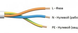
The circuit is connected to the grounding bus of the distribution system using a steel strip with a standard size of 24x4 mm or copper and flexible wire with a cross-section of 10 mm². In some cases, specifically specified in the PUE, it is allowed to use aluminum wire with a cross-section of 16 mm² for this purpose (see figure below).
Scheme of grounding installation in the panel
If there is a choice between the options proposed above, preference is given to copper wire, which has the most suitable characteristics for the task.
In the final part of the review, we draw the attention of users to the fact that it is not very easy to make a grounding loop with your own hands, since when carrying out this work, strict compliance with the requirements of the PUE is necessary. For those who are not completely confident in their abilities, there is always a “backup” way out - to invite representatives of an organization specializing in the manufacture of groundings
We ground ourselves
Metal beam joints: basic connection methods
When laying a grounding protection loop, first of all it is necessary to select the type of circuit according to which the work will be carried out. Experienced craftsmen recommend choosing a TN-CS type circuit. Its main advantage is that the equipment has direct contact with the ground. The neutral and ground contacts are made by one conductor, and at the entrance to the panel they are divided into 2 separate ones. This scheme provides reliable protection, so there is no need to install an RCD, just simple circuit breakers are enough. However, according to the PUE, it is necessary to comply with the requirements for mechanical protection of the common contact of neutral and earth (PEN), as well as create additional backup grounding on supports at a distance of 200 m or 100 m.
Creating a protective grounding loop is quite simple if you follow the rules listed below. First of all, to create a circuit, you need to choose a protective grounding scheme; there are several types, the most reliable and successful:
- closed (usually done in the shape of a triangle);
- linear.
In a closed circuit, all grounding conductors are buried in the ground, located at the same depth and connected to each other by a metal jumper. The main advantage is operability in the event of a rupture (from corrosion or other influences) of the metal jumper.
In a linear circuit, the conductors are lined up in one line and connected in series with each other by a jumper. This circuit is a little easier to create, but has a drawback - if the jumper is damaged, the entire system fails.
Creating a Ground Loop
So, to create a ground loop we will need the following tools and materials:
- Shovel.
- Welding machine (required).
- Metal saw or grinder.
- Sledgehammer.
- Pliers, wrenches.
- Metal corner/channel/U-shaped profile made of stainless steel with a length of two meters (with a cross-sectional area up to 150 mm²).
- Metal strips from 110 cm long, 4 cm wide, 4–5 mm thick.
- A metal strip of the required length (from the location to the point of contact with the house), width 4 cm, thickness 4–5 mm.
- Large bolts, nuts and washers (M8-M10).
- Copper wire with a thickness of at least 6 mm².
Once everything you need is available, you can begin installing the protective grounding. First of all, you should choose a place; it is best to choose a piece of land where people or animals are rarely located, since electric shock may occur when electricity is discharged into the soil. It is best to choose a place on the border of the site, at the maximum distance from the constant visitation zone.
After which it is necessary to dig a narrow trench 60–70 cm deep from the point of contact with the house to the point where electricity is discharged. In the place where electricity is discharged, it is necessary to dig a corresponding figure (depending on the chosen scheme) with sides of ~1.2 m between the conductors.
Then, in each corner of the figure (ours is a triangle), metal corners are dug into the ground to a depth of 2 m or more. Pre-prepared metal plates are welded to the protruding ends of the buried conductors, to one end of which a conductor strip is welded, going directly to the point of grounding contact with the house.
At the point of grounding contact, a copper wire is mounted to this plate, which already comes out of the ground and is led out into the electrical panel.
After this work is completed, the trenches are dug back in. At this stage, work on protective grounding can be considered completed.
Dimensions of the grounding sign according to GOST 21130-75
The specified GOST specifies not only the dimensions, but also the methods of applying the sign on the equipment of the manufacturer of panels and other electrical equipment. 4 types of designation are regulated:
- Stamping method.
- Casting in steel case.
- Impact method.
- Pressing method in plastic cases.
Clause 3.1 of the above GOST specifies the possibility of making signs using appliqué, paint, or photochemical methods. The only strict requirement is their size:
When casting or pressing on the body
| H | H1 | D* | b | h | r |
| 5 | 3,6 | 10 | 0,7 | 2,5 | 0,35 |
| 8 | 6,0 | 16 | 1,2 | 4,0 | 0,6 |
| 10 | 7,0 | 20 | 1,4 | 5,0 | 0,7 |
| 14 | 9,0 | 25 | 1,8 | 5,5 | 0,9 |
| 22 | 15,0 | 40 | 3,0 | 9,0 | 1,5 |
| 28 | 17,5 | 45 | 3,5 | 8,5 | 1,75 |
| 30 | 20,0 | 50 | 4,0 | 10,0 | 2,0 |
| 50 | 35,0 | 90 | 7,0 | 20,0 | 3,5 |
When manufactured using the impact method
| D | H | H1 | b | h | r |
| 14 | 8 | 6,0 | 1,2 | 2,5 | 0,6 |
| 18 | 10 | 7,0 | 1,4 | 5,0 | 0,7 |
| 25 | 14 | 9,0 | 1,8 | 5,5 | 0,9 |