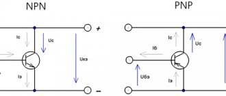
Types and designs of grounding
In private homes, PUE requirements allow the use of various types of grounding. The design of a conventional circuit includes vertical electrodes and one horizontal jumper. All elements must be the same size and have a circular cross-section. They are usually made from thick reinforcement, pipes or steel rods.
The classic figure is a ground loop with a triangle configuration, consisting of 3 reinforcing rods, measuring 2 meters or more. The greater the distance between the bars, the more efficient the system will work. The minimum distance is 1.5 m.
After the electrodes are driven into the ground, they are connected to each other. A separate strip is installed on each side, fixed at the same height. These are copper or steel horizontal grounding conductors installed on the top of the pins.
The place to install the circuit in a private house is chosen where people very rarely enter. Preference is given to the north side, which is poorly lit and helps retain a large amount of moisture in the soil. The distance from the contour to the wall of the house must be at least 1 meter.
In another embodiment, the grounding has a deep-type design. It has virtually no disadvantages characteristic of the conventional method, since a modular-pin system is used. The entire assembly kit, made at the factory, is technically confirmed by a certificate. The main advantage of these systems is their compliance with standards; they have an increased service life - from 30 years and above.
The electric charge spreads steadily, regardless of weather conditions. The depth of the electrodes reaches 30 meters, ensuring the quality and reliability of grounding, and the entire assembled circuit does not require constant checks.
Installation work
How to ground a private house and why
How to check and why do you need to choose the best place? This point is fundamental, since the safety of the ground loop depends on the choice of location. A mandatory condition is the installation of electrodes in a place where no one will be.
Land preparation. Using the triangle diagram as an example (Fig. 6).
Rice. 6 Prepared trenches for the triangle pattern.
The trench is dug to a depth of 50-80 cm. The sides of the triangle are 1.0-1.5 m long.
Installation of the structure:
Metal rods are driven in. To make them easier to penetrate into the ground, it is recommended to sharpen them (Fig. 7);
Rice. 7 Rods with pointed ends.
then connecting plates are welded to the tops of the rods (Fig. 8),
Rice. 8 Welded tops of rods with plates.
connecting the conductor to the plate through a bolt (Fig. 9), and at the very end we fill the grounding structure with earth.
Rice. 9 Cable connection using a bolt
At the end, it is necessary to measure the grounding and check the resistance of the entire circuit.
Connection diagrams
The most popular grounding connection schemes are:
Closed, in the shape of a triangle (Fig. 3). The main advantage is more stable and reliable operation. If the jumper between the rods is damaged, the circuit will still continue to work (but on the other side).
Rice. 3 Schematic diagram of a triangle
Linear (Fig. 4). Serial connection in one line of buried metal pegs. The disadvantage of such a circuit is that if the jumper fails, the circuit will not work.
Rice. 4 Schematic diagram of a linear view
In addition to the above types of contour diagrams, you can also use the following forms:
- rectangle;
- oval
Rice.
5 Shapes of ground loops Required tools and materials:
- welding machine;
- cutting tool (grinder);
- shovel;
- perforator;
- spanners;
- resistance meter;
- current meter;
- voltage meter.
In addition to the above devices, you must use:
- The corner is made of corrosion-resistant steel, its dimensions can be 50x50, 60x60 mm. Length – more than 2 meters. It is also possible to use a steel pipe with a diameter of at least 32 mm with a wall thickness of more than 3.5-4 mm.
- Metal strips (3 pieces). Their parameters: length – 120-130 cm; width – 4-6 cm; wall thickness – 4-6 mm.
- Steel strip made of stainless material 40x4, 50x5 mm. It connects the ground loop and the porch of the house.
- Bolts M10, M8.
- The conductor is copper, with a diameter of at least 6-7 mm2.
All the above parameters must be checked using a meter.
What is grounding
This is a complex consisting of metal structures and conductors, which ensures electrical contact of the electrical installation housing with the physical ground, that is, with the ground. The system begins with a ground electrode: a metal electrode grounded into the ground. These elements cannot be single; for reliability, they are combined into a grounding loop.
How it works
The external ground loop (which is located directly in the ground) is connected using a reliable conductor to the internal loop in the room, or to the grounding panel. Next, using an internal network of protective conductors, a connection is made to the housings of electrical installations and to the grounding contacts on switching devices (distribution boards, boxes, sockets, etc.).
Devices that generate electricity also have a grounding system to which the zero bus is connected. If an emergency occurs (a phase is connected to the electrical installation body), an electrical circuit arises between the phase conductor and the neutral bus along the ground line. The current strength in the emergency circuit spontaneously increases, the residual current device (circuit breaker) trips or the fuse insert burns out.
- the power cable does not ignite (fire hazard);
- The possibility of electric shock when touching the emergency housing of the electrical installation is prevented.
The resistance of the human body is tens of times higher than the grounding resistance. Therefore, the current strength (if there is a phase on the electrical installation body) will not reach a life-threatening value.
Testing
Upon completion of installation work, it is necessary to test the grounding loop for standardized indicators. The test will require precise measuring instruments, which are not always available to the user.
Checking the ground loop
In the absence of the required equipment, you should use the simplest methods, one of which is described below (it is only suitable for a private home).
First, you need to take a fairly powerful load (such as an iron, for example, with a consumption of about 2-4 kW). Secondly, you need a special adapter with a regular socket at one end (the second of them is made in the form of two separate wires). Next, one of them should be designed as an insulated single contact, and a thick loop should be made at the end of the second.
After this, you need to connect the resulting loop to a free block on the grounding bus in the panel. A single insulated contact should be plugged into the phase terminal of the socket closest to it (under no circumstances should you violate the order of connecting the ends of the adapter to the phase and ground). After all these manipulations, the heating device will be connected to the supply circuit through the resistance of a homemade ground loop. Then you need to measure the voltage in the network using a multimeter with and without the iron on.
A small difference in the readings of the two described measurements means that the manufactured ground electrode is fully operational. If they differ very much, the circuit will have to be modified (increase the number of pins, for example).
We talked about how to check the presence of correct grounding with a multimeter in the corresponding article!
What does grounding consist of?
- External ground loop. It is located outside the premises, directly in the ground. It is a spatial structure of electrodes (grounding conductors) connected to each other by an inseparable conductor.
- Internal ground loop. A conductive bus located inside a building. Covers the perimeter of each room. All electrical installations are connected to this device. Instead of an internal circuit, a grounding shield can be installed.
- Grounding conductors. Connecting lines designed to connect electrical installations directly to the ground electrode, or internal ground loop.
Take a closer look at these components.
External or outer contour
The installation of the ground loop depends on external conditions. Before starting the calculation and completing the design drawing, you need to know the parameters of the soil in which the ground electrodes will be installed. If you have built a house yourself, these characteristics are known. Otherwise, it is better to call surveyors to obtain an opinion on the soil.
What types of soils are there, and how do they affect the quality of grounding? Approximate resistivity of each soil type. The lower it is, the better the conductivity.
- Plastic clay, peat = 20–30 Ωm m
- Plastic loam, ash soils, ash, classic garden soil = 30–40 Ohm m
- Chernozem, shales, semi-hard clay = 50–60 Ohm m
This is the best environment to install an external ground loop. The current flow resistance will be quite low even with low moisture content. And in these soils the natural humidity is usually above average.
Semi-solid loam, mixture of clay and sand, wet sandy loam - 100–150 Ohm m
The resistance is slightly higher, but at normal humidity the grounding parameters will not exceed the standards. If there is prolonged dry weather in the installation region, it is necessary to take measures to forcibly moisten the installation sites of ground electrodes.
Clay gravel, sandy loam, wet (constant) sand = 300–500 Ohm m
Gravel, rock, dry sand - even with high general humidity, grounding in such soil will be ineffective. To comply with standards, deep grounding will have to be installed.
Many facility owners, saving on matches, simply do not understand why a grounding loop is needed. Its task, when connecting a phase to the ground, is to ensure the maximum value of the short circuit current. Only in this case will the protective shutdown devices operate quickly. This cannot be achieved if the current flow resistance is high.
Having decided on the soil, you can choose the type, and most importantly, the size of the ground electrodes. Preliminary calculation of parameters can be performed using the formula:
The calculation is given for vertically installed grounding conductors.
Decoding the formula values:
- R0 is the resistance of one ground electrode (electrode) obtained after calculation in ohms.
- Rekv - soil resistivity, see information above.
- L is the total length of each electrode in the circuit.
- d is the diameter of the electrode (if the cross-section is circular).
- T is the calculated distance from the center of the electrode to the surface of the earth.
By setting known data, as well as changing the ratio of values, you should achieve a value for one electrode of the order of 30 Ohms.
If the installation of vertical grounding electrodes is not possible (due to the quality of the soil), the resistance value of horizontal grounding electrodes can be calculated.
Therefore, it is better to spend more time driving vertical rods than to monitor the barometer and air humidity.
And yet we present the formula for calculating horizontal grounding conductors.
Accordingly, decoding of additional quantities:
- Rв is the resistance of one ground electrode (electrode) obtained after calculation in ohms.
- b - width of the electrode - grounding conductor.
- ψ is a coefficient depending on the weather season. The data can be taken in the table:
ɳG is the so-called demand coefficient for horizontally located electrodes. Without going into details, we get the numbers from the table in the illustration:
Preliminary calculation of resistance is necessary not only for proper planning of material purchases: although it will be a shame if you don’t have enough electrode to complete the work, and the store is several tens of kilometers away. A more or less neatly drawn up plan, calculations and drawings will be useful for resolving bureaucratic issues: when signing documents on acceptance of an object, or drawing up technical specifications with an energy sales company.
Of course, no engineer will sign papers only on the basis of even beautifully executed drawings. Spread resistance measurements will be taken.
Bottom line
To summarize all that has been said, let’s pay attention to the recommendations shared by experienced craftsmen:
- Before starting installation work, it is advisable to prepare a drawing of the future structure, which may be needed during further operation. If it is available, it is easier to recall the layout of the pins in memory.
- Electrode segments can be driven in not only at the corner points of the triangle. They can be placed either in a line or in an arc. The main thing is that the total resistance to current flow created by the entire chain does not exceed 3-4 ohms.
- If it is greater than the normalized value, then the system will have to be modified by adding a couple more rods to it.
- If you have no experience in checking ground resistance yourself, it is best to invite a specialist.
After familiarizing yourself with all the intricacies of the process of assembling and testing the ZK, anyone can try to make it with their own hands.
Grounding calculation for a private house: formulas and examples
Grounding calculations for a private home are based on formulas for calculating the resistance to current spreading for electrodes. Examples will be shown below.
Soil resistance
For a single rod, the formula is applied:
where ρ eq is the equivalent resistivity of a single-layer soil (selected according to Table 1 for a specific soil);
- L—electrode length (m);
- d—electrode diameter (m);
- T is the distance from the middle of the electrode to the ground surface (m).
Table 1
Dimensions and distances for ground electrodes
The number of electrodes in the circuit can be calculated using the formula, where:
Rн is the maximum permissible total circuit resistance (for a network of 127-220 V - 60 Ohms, for 380 V - 15 Ohms), Ψ - climatic coefficient (determined according to Table 2).
table 2
Electrode sizes are selected taking into account actual conditions and recommendations:
- pipe - minimum wall thickness 3 mm, diameter - depending on the availability of material;
- steel bar - diameter not less than 14 mm;
- corner - wall thickness 4 mm, size - according to the availability of material;
- strip for linking electrodes - width - at least 10 mm, thickness - more than 3 mm.
The depth of penetration (length of the electrodes) is selected from the condition - at least 15-20 cm below the freezing level. The minimum length is 1.5 m. The pin installation step is 1-2 times the length of the electrode, and the minimum distance is 2 m.
Watch this video on YouTube
Video
Coffee capsule Nescafe Dolce Gusto Cappuccino, 3 packs of 16 capsules
1305 ₽ More details
Coffee capsules Nescafe Dolce Gusto Cappuccino, 8 servings (16 capsules)
435 ₽ More details
Batteries
Circuit design
Components
The previously mentioned grounding resistance (Rз) of the circuit is the main parameter controlled at all stages of its operation and determines the effectiveness of its use. This value must be so small as to provide a free path for the emergency current tending to flow into the ground.
Note! The most important factor that has a decisive influence on the value of grounding resistance is the quality and condition of the soil at the site of the installation. Based on this, the charger in question or the ground loop of the charge circuit (which in our case is the same thing) must have a design that meets the following requirements:
Based on this, the charger in question or the ground loop of the charge circuit (which in our case is the same thing) must have a design that meets the following requirements:
- It must include a set of metal rods or pins with a length of at least 2 meters and a diameter of 10 to 25 millimeters;
- They are connected to each other (necessarily for welding) by plates of the same metal into a structure of a certain shape, forming a so-called “grounding conductor”;
- In addition, the device includes a supply copper busbar (also called electrical) with a cross-section determined by the type of equipment being protected and the magnitude of the drain current (see the table in the figure below).
These component devices are necessary to connect the elements of the protected equipment with the descent (copper busbar).
Differences in device location
According to the provisions of the PUE, the protective circuit can have both external and internal design, and each of them is subject to special requirements. The latter establishes not only the permissible resistance of the ground loop, but also stipulates the conditions for measuring this parameter in each particular case (outside and inside the object).
When dividing grounding systems according to their location, it should be remembered that only for external structures the question of how the grounding resistance is normalized is correct, since it is usually absent indoors. Internal structures are characterized by wiring of electrical busbars along the entire perimeter of the premises, to which grounded parts of equipment and devices are connected through flexible copper conductors.
For structural elements grounded outside the facility, the concept of re-grounding resistance is introduced, which appeared as a result of the special organization of protection at the substation. The fact is that when forming a neutral protective conductor or a working conductor combined with it at the supply station, the neutral point of the equipment (step-down transformer, in particular) is already grounded once.
Therefore, when another local grounding is made at the opposite end of the same wire (usually a PEN or PE bus connected directly to the consumer panel), it can rightfully be called repeated. The organization of this type of protection is shown in the figure below.
Important! The presence of local or repeated grounding allows you to insure yourself in case of damage to the protective neutral wire PEN (PE - in the TN-CS power supply system). Such a malfunction is usually found in technical literature under the name “zero burnout”
Such a malfunction is usually found in technical literature under the name “zero burnout.”
Self-production
After preparing all the necessary materials and choosing a suitable place for arranging the grounding, you can proceed to the direct operations of assembling the grounding loop. At the preparatory stage, pipe or other profile sections are cut, the size of which is chosen to be 20-30 cm larger than the calculated one (this is necessary to compensate for the bending of the top of the workpiece when it is driven into the ground).
Additional Information. To make it easier to hammer in such sections, it is recommended to sharpen their lower edge using a grinder with a trimming disc.
Simultaneously with the preparation of point pin grounding conductors, the stage of excavation begins, consisting of the preparation of grooves with beveled edges (to better retain the soil from shedding).
The order of operations performed during excavation work is as follows:
- First, the site for the future ground loop is prepared (cleared) and its markings are made;
- Then, using the already applied markings, grooves are dug with a depth of 70-80 cm and a width of about 50 cm (the depth is chosen to minimize corrosion of metal bonds);
- After this, the pins, cut to length, are driven in at the designated points so that about 20 cm protrude above the surface (see photo below);
Arrangement of a grounding loop
- Upon completion of the installation of all vertical elements, their upper parts are cut off, and the contact pads are thoroughly cleaned, after which metal connections are welded to them;
- After all welding seams have cooled, they are cleaned with a grinder and a grinding disc, and then painted with a special tar-based protective paint;
Note! Only the areas of welded joints that are most susceptible to corrosion are painted.
- Next, from the short-circuit point closest to the residential building, a ditch is dug to the same depth that was dug under the metal connections (its width may be slightly smaller, since the connecting strip is made solid and does not require welding);
- Then a strip of metal with a standard size of at least 25x4 mm is laid in the prepared trench, which is subsequently welded to a pin or jumper (metal bond);
- At the final stage of work, near the wall of the house, the already laid metal strip is raised to a height of about 200 mm, where a busbar (wire) is connected to it by bolting or welding, going to the main distribution board (photo below).
Input of grounding into the house
To connect the finished grounding to the existing power supply circuit, you will need to familiarize yourself with the existing grounding schemes.
Entering the house
The circuit is connected to the grounding bus of the distribution system using a steel strip with a standard size of 24x4 mm or copper and flexible wire with a cross-section of 10 mm². In some cases, specifically specified in the PUE, it is allowed to use aluminum wire with a cross-section of 16 mm² for this purpose (see figure below).
Scheme of grounding installation in the panel
If there is a choice between the options proposed above, preference is given to copper wire, which has the most suitable characteristics for the task.
In the final part of the review, we draw the attention of users to the fact that it is not very easy to make a grounding loop with your own hands, since when carrying out this work, strict compliance with the requirements of the PUE is necessary. For those who are not completely confident in their abilities, there is always a “backup” way out - to invite representatives of an organization specializing in the manufacture of groundings.
Standards of PUE grounding
Grounding PUE standards are a set of regulatory legal acts. These rules include recommendations on how to carry out electrical wiring correctly, a description of various electrical installations and the principle of their operation, as well as the requirements for electrical systems and their components.
Grounding installation work must be carried out in accordance with the electrical installation regulations. The criteria defined in the PUE will allow all connections to be made without errors, maintaining all standards. This guarantees reliable operation of the protective system in the house and will avoid the negative consequences of natural and man-made impacts.
If you unquestioningly follow all the rules described in the PUE, this will lead to large financial costs, so electricians and engineers follow only very important recommendations in their activities.
In accordance with the rules of the PUE, a repeated protective circuit must certainly be located at the exit areas from the premises. It is recommended to install natural grounding electrodes at this location. These include reinforced concrete devices, large metal parts, which for the most part are directly connected to the ground.
The PUE also specifies items that cannot be used as grounding conductors: energized metal objects, sewer and heating pipes, as well as pipelines with flammable substances.
When installing grounding, it is necessary to carefully carry out calculations, taking into account all the factors affecting the quality of the device being created, and it is necessary to follow the PUE.
Ready-made kits or manual assembly?
Many owners who decide to make a grounding loop with their own hands may have a reasonable question: isn’t it easier to use ready-made grounding kits?
No, it’s not simpler; more precisely, it’s not always simpler, and sometimes even more expensive. Ready-made kits are a compromise solution, since with time savings you get a higher cost, but the quality of the materials is not always the same.
Most stores sell modular or linear circuits, which are relatively cheaper, but do not always provide the proper quality of electrical conductivity.
By independently selecting and connecting all the components, you will be 100% confident in the quality of the grounding circuit, and therefore in the safety of the entire house. But you shouldn’t give up ready-made kits - they are perfect for arranging a small dacha or cottage, garages and utility rooms equipped with an electrical network.
Before you bury the entire structure, it is necessary to paint the visible part of the contour for reliable protection against corrosion. It is best to clean the entire plane of the elements, since poor preparation before painting will lead to accelerated corrosion of the metal.
After completing all installation work, you need to bury the trenches. Another tip is that before digging, you can fill the fresh soil with a saline solution, which increases the conductivity of the circuit. To prepare it, follow the proportion of 2-3 kg of salt per 10 liters of water. Afterwards, you need to carefully compact the soil for better contact with the contour; low density has a negative effect on soil resistance indicators.
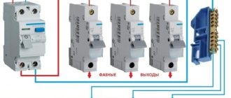
Grounding switches
1.7.109. The following can be used as natural grounding electrodes:
1) metal and reinforced concrete structures of buildings and structures that are in contact with the ground, including reinforced concrete foundations of buildings and structures that have protective waterproofing coatings in non-aggressive, slightly aggressive and moderately aggressive environments;
2) metal water pipes laid in the ground;
3) casing pipes of boreholes;
4) metal sheet piles of hydraulic structures, water conduits, embedded parts of valves, etc.;
5) rail tracks of main non-electrified roads and railways and access roads in the presence of a deliberate arrangement of jumpers between the rails;
6) other metal structures of structures located in the ground;
7) metal shells of armored cables laid in the ground. Cable sheaths can serve as the only grounding conductors when there are at least two cables. Aluminum cable sheaths are not allowed to be used as grounding conductors.
1.7.110. It is not allowed to use pipelines of flammable liquids, flammable or explosive gases and mixtures, and sewerage and central heating pipelines as grounding conductors. The specified restrictions do not exclude the need to connect such pipelines to a grounding device for the purpose of equalizing potentials in accordance with 1.7.82.
Reinforced concrete structures of buildings and structures with prestressed reinforcement should not be used as grounding conductors, however, this restriction does not apply to overhead line supports and outdoor switchgear support structures.
The possibility of using natural grounding conductors based on the density of currents flowing through them, the need for welding reinforcing bars of reinforced concrete foundations and structures, welding anchor bolts of steel columns to reinforcing bars of reinforced concrete foundations, as well as the possibility of using foundations in highly aggressive environments must be determined by calculation.
1.7.111. Artificial grounding conductors can be made of black or galvanized steel or copper.
Artificial grounding conductors should not be painted.
The material and smallest dimensions of grounding conductors must correspond to those given in Table 1.7.4.
1.7.112. The cross-section of horizontal grounding conductors for electrical installations with voltages above 1 kV should be selected according to the condition of thermal resistance at a permissible heating temperature of 400 °C (short-term heating corresponding to the duration of the protection and tripping of the circuit breaker).
If there is a risk of corrosion of grounding devices, one of the following measures should be taken:
increase the cross-sections of grounding conductors and grounding conductors, taking into account their estimated service life;
use galvanized or copper grounding conductors and grounding conductors.
In this case, one should take into account the possible increase in the resistance of grounding devices due to corrosion.
Trenches for horizontal grounding conductors must be filled with homogeneous soil that does not contain crushed stone and construction waste.
Grounding electrodes should not be located (used) in places where the ground is dried out by the heat of pipelines, etc.
Types of material (profiles)
According to the requirements of the PUE, which contain instructions on what the resistance of current flow in the ground should be, in most cases this indicator is set at a level of no more than 4 ohms. To obtain this value, you usually have to make a lot of effort to adhere to the same technology requirements.
First of all, this concerns the materials used in assembling the grounding loop, selected based on the following conditions:
- When choosing pins, preference should be given to ferrous metal blanks;
- The most commonly used rod is a standard size of 16-20 mm or a corner with parameters 50x50x5 mm and a metal thickness of about 5 mm;
- It is not allowed to use reinforcement as circuit elements, since it has a hardened surface that affects the normal flow of current;
- For these purposes, it is pure rod that is suitable, and not its reinforcement substitute.
Note! For areas with dry summers, thick-walled metal pipes are best suited, the lower end of which is flattened into a cone, and then several holes are drilled in this part of the pipe. According to the provisions of the PUE, before placing them in the ground, holes of the required length are first drilled, since driving them manually is quite problematic
In the case of a particularly dry summer and a sharp deterioration in the parameters of the ground electrode, a concentrated saline solution is poured into the hollow parts of the pipes, which makes it possible to obtain the resistance that should be in accordance with the requirements of the PUE. The length of pipe blanks is selected within 2.5-3 meters, which is quite enough for most Russian regions
According to the provisions of the PUE, before placing them in the ground, holes of the required length are first drilled, since driving them in manually is quite problematic. In the case of a particularly dry summer and a sharp deterioration in the parameters of the ground electrode, a concentrated saline solution is poured into the hollow parts of the pipes, which makes it possible to obtain the resistance that should be in accordance with the requirements of the PUE. The length of pipe blanks is selected within 2.5-3 meters, which is quite enough for most Russian regions.
This type of profile blanks has special requirements regarding the order of their placement in the soil and consists of the following:
- Firstly, the pipe elements of the protective circuit must be placed at a depth exceeding the soil freezing level by at least 80-100 cm;
- Secondly, in particularly dry areas, approximately a third of the length of the ground electrode should reach wet soil layers;
- Thirdly, when fulfilling the second condition, one should focus on the peculiarities of the location of the so-called “groundwater” in a given region. If they are located at a significant depth, according to the rule formulated in the provisions of the PUE, it will be necessary to prepare longer pipe sections.
The type and profile of the pin blanks used in the construction of the grounding switch can be found in the figure below.
In practice, in most regions of Russia, a steel corner and a strip of the same metal are usually used. In order to obtain more accurate parameters of the grounding elements used, geological survey data will be required. If this information is available, it will be possible to involve specialists in calculating the parameters of the ground electrode.
Influence of soil on resistance Rз
Grounding calculation
It has been practically proven that the resistance of the grounding device is largely determined by the condition of the soil at the location of the ground electrode. In turn, the characteristics of the soil in the area of protective work depend on the following factors:
- Soil moisture at the work site;
Additional Information. When assessing moisture content, you should know that shale and clay retain water well, while sandy soils, on the contrary, do not.
- The presence of rocky components in the soil, in which it is simply impossible to arrange grounding (in this case, you have to choose another place);
- Possibility of artificial soil moisture during particularly dry summer periods;
- Chemical composition of the soil (presence of salt components in it).
Depending on the composition of the soil, it can be classified as one or another type (see photo below).
Different types of soil
Based on the peculiarities of the formation of the resistance of the ground electrode, which suggests its decrease when moistened and the salt concentration increases, in case of emergency, portions of the wet chemical NaCl are artificially introduced into the soil.
Good soils from the point of view of grounding arrangement are loamy soils with a high content of peat components and salts.