Hello, dear readers of the site. There comes a time when, after installation work, the testing and marking of electrical cables , followed by the assembly of the electrical installation circuit. And when you look into a new panel or cabinet, and in front of you is a bunch of cables with bundles of wires protruding, then at the first moment the question involuntarily arises: “How and what to do with this?”
In fact, cable testing is not as complicated an operation as it seems. The main thing here is to understand the principle and be able to use the devices that you use for dialing.
Today, special measuring devices
or use
ready-made cable core markings
produced at the manufacturer.
Cable testing using a handset or headset
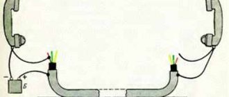
Since ancient times, wire testing has been carried out by two installers, each of whom was equipped with a handset or headset. One of them connected a source (battery or generator) to the line to power the microphones of the test tubes with a voltage of 12 - 100 V as shown in the figure.
1 — box type BKT; 2 - screw for fastening the plinth, communicating with the cable screen; 3 - screen wire; 4 - bundles of cable cores; 5 - braid with ringed pairs
Rice. 1 Cable testing using test handsets and a 12 - 100 V generator
One of the source terminals was connected directly to the cable screen, the other, through the test tube of one of the installers, was connected to a copper pair or group of pairs that needed to be identified at the return end. The second installer connected one of the terminals of the telephone handset to the cable screen, while the other one touched the cable cores one by one. The identification of the required pair was indicated by a click that was heard in the lineman's telephone receiver after it came under voltage. This also created a voice communication channel between the installers. Moreover, to organize voice communication during pair identification, it was enough for the second installer to short-circuit all the wires with each other and connect to them with the free terminal of the handset. The main disadvantages of the tubes are the poor audibility of clicks, the need to physically connect to the cable, as well as the inconvenience of work: the installer has to press the tube to his ear, and at the same time connect to different wires with his hands.
• Telephone
.
Concept and history • Basic components of a telephone set • Diagram and description of the operation of a telephone set • Dialing:
definition and types
⇒ Cable line testing with telephone handsets
•
Fiber testing
• OB testing using measuring instruments • Fiber optic couplers-clothespins
Dial cable line using telephone handsets
Checking the cable line with fitter tubes or continuity testing
Fitter's telephone receiver. Portable telephone device.
This device can hardly be called a device or even a tool. However, telephone operators use it to identify almost all damage to cable and wire communication lines. It is used everywhere and is a mandatory attribute of the profession of a connected electrician. The presence of this thing in a person’s hands, as a rule, allows ordinary people to identify him as a signalman without any identification. We are talking about the telephone operator's handset.
Official name: portable telephone
. Currently, they are produced by industry and can have many different functions, but further we will talk about homemade products that are widespread in communications.
As a rule, it is made on the basis of a handset from an old rotary telephone. On the inside, between the microphone and the telephone capsule, a disk dialer from the same device is attached with screws or bolts. The type, color and other attributes depend on the capabilities of the installer or workshop that produces it. All this: microphone, telephone, dialer, are connected in series. Moreover, the disk dialer is connected in such a way that the counting contacts repeatedly open the circuit at the moment of the reverse motion of the disk, thereby ensuring dialing.
Fig.1. Telephone handset diagram.
Enlarge photo, more details
In construction organizations, they often use tubes without a dialer (photo on the right), because there it is used only for dialing. In operation, on the contrary, a handset without the ability to dial a number is useless.
It is advisable to use an old carbon microphone in the handset, not an electronic one. A telephone capsule, on the contrary, is better to take a modern, louder one. A correctly assembled handset, when connected to a telephone pair of wires, should cause a response from the station; a dial tone is heard in the telephone capsule. The number should be dialed accordingly. Usually, homemade work is not complicated by contacts that block the phone while dialing a number, so loud clicks are heard in the handset when dialing a number. Two cords coming out of the tube end in crocodile clips.
You can use this device with a battery of batteries, preferably more than 12 volts, switched on in series, but in operation they often use station power (“-” taken from a telephone pair). The search is simple: one wire of the cord is grounded, the second one sequentially touches the contacts on the plinth. A loud click in the tube is used to determine nutrition. Actually, all damage is determined by the volume of the click, that is, by ear.
Message
determined by connecting one contact to ground. The second one touches the line being tested. Naturally, the station power is turned off. If the click is loud, it means there is extraneous voltage on the wire, that is, a message.
Earth
determined by connecting one wire to the power supply. The second one touches the wire being tested. A loud click indicates reduced insulation on that wire. The complete absence of a click indicates the absence of capacitance, that is, an imminent wire break. The click should be barely audible, but it should be there.
A short
they recognize the same as the ground, while the second wire of the pair being tested is grounded.
Using this device, you can use the phone number to find the desired pair in the distribution cabinet, call anywhere from it, or eavesdrop on someone’s conversation, but this is already a crime and there is no advice on this topic on this site.
Continuity when installing a cable line.
Continuity during installation
cable line is described in the “Manual...” on the page Installation of prefabricated couplings.
→ → Call protocol forms
cable from the “Unified Guide...”
You can ring the cable without a microphone in the handset: read “If the microphone in the handset has shorted.”
Continuity when checking an installed cable line
Two tubes and some kind of power are used to test the cable. That is, to check the integrity of the cores and their correct installation or to select cable pairs during assembly. When dialing, the tubes are connected according to the following schemes:
Fig. 2. Scheme for checking the cable installation (continuity) of the cable with the battery through the “ground”
Fig.3. Scheme for checking cable installation (continuity) of a cable with station power via ground
Regarding the ““-” taken from the telephone pair,” the minus in this diagram and at the same time about the polarity of the station power supply, there is a page from the “Question and Answer” section Voltages on a wired/landline/home telephone set under different operating modes
Fig.4. It is possible to switch on not through the ground, but through the cable shield. Additionally, the integrity of the screen is checked
There are generally accepted two sequences of calling: “in pairs” or “in a row.”
In pairs.
The first installer touches the tube contact to 2 wires of the pair at the same time. The second one checks for the presence of “click” voltage on both cores of its plinth. Next, having made sure that both wires reach, the second one gives the command to the first one through the tube: “one”. The first installer switches to core “a”. The second one checks for the presence of a click on core “a” and its absence on the second core “b”, that is, it checks the pair for a short circuit. Then he gives the command to the first one: “further.” The first one switches to 2 wires of the next pair. The process is repeated.
Poreously.
The first concerns only the “a” core of the pair. The second one checks core “a” for a “click” and core “b” for its absence. He returns to core “a” and gives the command “further”. The first one switches to core “b”. The second one checks its presence on this vein and gives the command “further” using it. The process is repeated for the next pair.
From the outside, the dialogue between the installers can be heard either as “one, further, one, further...”. Or: “further, further, further...”.
Such a continuity test allows you to make sure that the installation is correct and that there are no wire breaks or “grounds” on these wires. But it does not guarantee verification of the absence of messages, as well as breakdowns (various parks) collected by dialing. According to the rules, messages and breakdowns should be determined during further measurements (with alternating current or on a working capacitance), but this often depends on the capabilities or integrity of the meters.
→ → Call protocol forms
cable from the “Unified Guide...”
Selecting a measurement method based on the nature of cable damage
Test to determine the nature of the damage
When it comes to cable damage, continuity becomes more difficult. In a damaged cable, it is advisable to find out exactly which core is connected, and which is broken. Therefore, here it is necessary not only to check each pair for short, but also to “click” all other cable pairs for a message. It is useful for the tester to know the whole picture of the damage in order to correctly determine the methods and conductors for measurements.
In practice, in the event of an incomplete cable break, as well as when the coupling leaks, it rarely happens that all the cores are “grounded” or communicated in the same way. Typically, the damage picture looks schematically like this:
Fig.5. Diagram explaining the electrical nature of cable damage
Analyzing this picture, you can, for example, notice that the “a” of the 1st pair lived in a cliff. For it, as well as for cores “b” of the second and third pairs (5 kOhm), the pulse measurement method is suitable.
Core “b” of the first pair is practically “clean”, that is, it can be used for measurements using bridge methods. For example, by short-circuiting cores 2b, 3b and 1b on side “B”, you can apply the Murray method (theory) (PKP-5) (for IRK-PRO “leakage”). Connect core 1b to the 1st terminal of the device (for IRK-PRO class A). The ratio of the insulation of a “clean” core to a damaged one will in this case be 4000/5=800, which is quite satisfactory for this method.
In the absence of such capabilities, you can even use core 4b (34 kOhm), but for the Kupfmüller method (PKP-5) (K coefficient for IRK-PRO), the error in this case will be greater, but it will already be possible to navigate the route.
And finally, to turn on the generator (contact search method), it is better to use a core with the least insulation, in this case, or, as usual, a cable shield (4 kOhm)
Solving such problems often resembles solving a rebus, and the more the meter knows and uses measurement methods, the less likely it is to make an error. Do not rush to connect the generator without deciding on the search area. As it was said in the famous cartoon, “ It’s better to lose an hour, but then fly in 5 minutes.”
»
There is a small page on this topic about my first cable damage.
• Telephone
.
Concept and history • Basic components of a telephone set • Diagram and description of the operation of a telephone set • Dialing:
definition and types
⇒ Cable line testing with telephone handsets
•
Fiber testing
• OB testing using measuring instruments • Fiber optic couplers-clothespins
What is a cable continuity test kit?
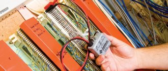
With the passage of time and the development of technology, specialized devices for testing cable pairs - test kits - appeared. The tone generator included in them is capable of not only supplying power to the microphones of the test tubes for organizing voice communication, but also sending a tone signal to the pair for easy identification at the return end. As the signal propagates along the conductor, it creates an electromagnetic field around it, which is detected by the receiver at the remote end.
Rice. 2 Organization of an official communication channel between installers using the Greenlee 77HP generator
As a receiver, you can use a test handset (headset), one of the terminals of which should be connected to the cable screen, the other should be used as a probe. However, it is more practical for this purpose to use a special inductive probe, which is also an integral part of the test kit.
Fig.3 Identification of a pair at the opposite end of the cable using the Greenlee 200EP-G inductive probe
A loud signal from the generator will be perfectly audible in the speaker of the probe even without direct contact of its tip with the desired pair, however, as you approach it, the signal level will be higher, which makes it easy to cope with the task. Some inductive probes have connectors for connecting a telephone headset and even a test handset.
Checking electrical circuit parameters
When testing electrical circuits, you can test many of their parameters. This includes current, network voltage, and signal frequency. But to determine serviceability, you only need to ring the circuit for integrity and check the insulation resistance. Both can be done with a multimeter.
In order to know how to test electrical wiring with a multimeter, you need to correctly configure the measuring device and correctly perform the measurement steps. To check the integrity of the wire you need:
- Connect the black probe of the multimeter to the socket labeled COM, and the red one to the socket labeled U, Ω, Hz;
- The meter knob must be set to the 20 Ohm position;
- Connect the measuring contacts to both ends of the wire. If the ends are in different places in the room, you need to use a previously tested extension wire;
- The tester screen will display the value. If the value does not exceed 2 ohms, it means that the integrity of the wire is not compromised. If the readings are not at the same level or more than 8-10 ohms, then there is a break in the circuit.
In the same way, wires in a car and cables of various electronic devices are tested.
In addition to checking integrity, wires are tested for insulation resistance. This can also be done with a multimeter:
- The probes remain in the same holes as when checking integrity;
- The measurement mode selected is the same - resistance test;
- The measurement limit must be selected as large as 20 or 200 megaohms;
- Touch the probes to opposite conductors of the cable: phase and neutral or phase and screen. In a car, this is ground and signal wire;
- The screen should remain displaying infinity; if there is any value instead, it means there is a short circuit somewhere. Changing values indicate interference in the network.
In addition to ordinary wires, there are high-voltage wires that can withstand high current and voltage loads. These include spark plug wires in cars. The current that is required when starting the engine flows through them; this current reaches 80-150 amperes. Knowing how to test high-voltage wires with a multimeter is required when diagnosing car electronics. The ringing of these wires occurs according to the indicated diagram , with the difference that it is necessary to set a larger resistance measurement limit. Typically this limit should be set at 20 kilo-ohms.
After this, you need to find the ends of the wire and connect the multimeter probes to them. The resistance of this wire will be displayed on the device screen. It should be in the range from 1 to 10 kOhm.
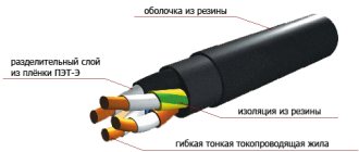
In trucks, as well as in networks located in places subject to constant mechanical stress, conductors with a screen - armor or armored wires - are placed. The only special feature of the armored wire is the screen, made of durable metal. You can check the integrity and insulation of the armored wire in the same way as a regular one, you only need to have access to its ends and the screen outlet.
Read also: What are springs made of?
Analog inductive probes
Analog inductive probes can accurately identify the pair of wires at the remote end, but the pair must be disconnected from the active equipment and open circuit. In addition, such receivers are unlikely to be able to trace a line under plaster and behind a false wall. This is only possible if used in conjunction with a high power generator. At the same time, they are good at identifying low-frequency harmonics emanating from power wiring under load. This allows tracing hidden under plaster or in a hollow wall.
Video of wiring traced with an inductive probe:
The most popular and universal inductive probes are the following models:
| 200B-G | TEP-200 | CT15 | 200EP-G | |
| LED indication | • | • | ||
| Sound indication | • | • | • | • |
| Frequency range of the received signal | 500 Hz – 5 kHz | 100 Hz – 20 kHz | 500 Hz – 5 kHz | |
| Volume | 30 dB | 30 dB | ||
| Determining the polarity of a telephone line | • | |||
| Received signal type | analog | analog | analog | analog |
| Pairing with a headset | • | • | ||
| Pairing with a handset | • | • | ||
| Workspace lighting | • | |||
| Tip type | plastic | plastic | plastic | metal, plastic |
They are compatible with all (regardless of manufacturer) analog signal generators whose output frequencies are within the operating range of the inductive probe.
Continuity of wires from batteries and light bulbs
There is a clever and simple way to make a dial from a battery and a light bulb, which is used by many electricians.
Before carrying out this procedure, you must turn off the electrical current to all wiring. This homemade wiring tester consists of:
What kind of lighting do you prefer?
Built-in Chandelier
Important. All this is included in the circuit in series.
The first connecting alligator wire is connected to one of the ends that needs to be ringed, the second to the remaining one.
As a result, a series circuit consists of a current source, an alligator wire, a light bulb and another current source.
A conclusion about the integrity of the circuit can be made when the light bulb lights up.
DIY sound probe. A simple audio tester for continuity testing
Probes with sound indication consume slightly more current compared to the previous one, so during long breaks in operation it is advisable to turn off the power source.
Expert opinion
It-Technology, Electrical power and electronics specialist
Ask questions to the “Specialist for modernization of energy generation systems”
Do-it-yourself hidden wiring detector - the simplest circuits. Moreover, it is not at all necessary to make the design small-sized, the indicator itself can be assembled in a small box, and the bracelet and probe can be connected to it with flexible conductors. Ask, I'm in touch!
Analog inductive probes with filtering system
The higher the gain of the probe, the weaker the signal we can detect and the longer the line we can ring. The metal tip, which is supplied with some devices, also allows you to increase the sensitivity of the probe. However, along with the useful signal, the probe will receive and amplify all interference within the received frequency range. Therefore, in rooms with a high level of electromagnetic interference (server rooms, data centers, etc.), it is more convenient to use devices with a filtering system. Some of them allow you to filter out low-frequency noise of 50 Hz and their harmonics, others select a specific frequency, cutting off all kinds of interference (in this case, the selected receiving frequency must correspond to the frequency of the generator signal). These probes include the following:
| 200FP | PRO3000F50 | 200XP | 500XP | |
| LED indication | • | • | • | • |
| Sound indication | • | • | • | • |
| Frequency range of the received signal | 500 Hz – 5 kHz | 500 Hz – 5 kHz | 200 Hz – 3 kHz | |
| Low pass filter 50 Hz | • | • | • | • |
| Selective filter, frequency | No | No | 984 Hz | 577 Hz; 984 Hz |
| Volume | 35 dB | 35 dB | 60 dB | |
| Received signal type | analog | analog | analog | analog |
| Pairing with a headset | No | • | No | • (headset included) |
| Pairing with a handset | • | No | • | No |
| Tip type | plastic | plastic | plastic | metal, plastic |
| Waterproof/Shockproof | No | No | No | • |
For a video review of searching for a port with a probe with a filter, watch starting at 5:08:
Digital inductive probes
Probes with the ability to receive a digital signal are not sensitive to various kinds of interference and noise. However, such probes only work with “native” generators. In addition, the digital signal has a very strong electromagnetic effect on surrounding pairs and even cables. On the one hand, this makes it easy to trace cables located behind a false wall or suspended ceiling, and to identify the cable on the side remote from the generator. On the other hand, it does not allow you to select a specific pair to which the signal is sent. To solve this problem, some probes combine analog and digital operating modes. These probes include the following:
| 256712D | IT200 Probe | |
| LED indication | • | • |
| Sound indication | • | • |
| Fault identification: reversed pairs, short circuit, open circuit | • | • |
| Interfaces for cable connection | RJ45 | RJ45 |
| Analog signal reception | • | • |
| Digital signal reception | • | • |
| Determining the polarity of a telephone line | • |
In addition, devices of this type, together with their “own” tone generator, allow you to determine the presence and type of damage in a twisted pair cable (correct crimping) with an RJ45 connector. Therefore, they are most often used when servicing local computer networks.
Do-it-yourself testing of wires and cables (device)
- Make sure there is voltage at the input and output of the machine. If it is, you can proceed to further verification.
- Prepare the device for operation and check its serviceability by short-circuiting the measuring leads.
- Unscrew the lamp from the socket.
- Touch one of the measuring probes to the base (the metal part of the lamp with threads), and the second to the central contact of the lamp (the insulated center of the end part of the base).
- A sound signal and instrument readings that are different from 0 or 1 mean that the lamp is working. If it is faulty, you need to replace it, which will solve the problem.
- We check the cartridge for serviceability. To do this, you need to disassemble the lamp, make sure that the connected wires and contacts are intact. If everything is in order, then the cause of the failure is not in the cartridge. If malfunctions are detected, they must be eliminated. The lamp cannot be screwed in yet.
- We check the serviceability of the room switch. To do this, remove the plastic cover, unscrew the screws and take it out of the mounting box. We inspect the equipment for the appearance of carbon deposits and check the tightness of the fasteners. If everything is in order, you need to install the measuring ends of the tester on the contacts of the switch. The appearance of a sound signal when dialing in the on position will indicate that the equipment is working properly. The wires do not need to be disconnected.
Capacitive antennas
There are also test kits that use a capacitive antenna as a receiver. It detects the magnetic component of the field created by current flowing through the wires. To obtain a strong magnetic field, the pair must be short-circuited at the remote end. The antenna allows you not only to identify a cable in a cable well or cross-connection, but also to trace it in the wall and even in the ground. A representative of this type of device is the Greenlee CTS 132J, which is essentially an intermediate link between test kits and locators.
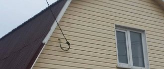
Purpose of hidden electrical wiring alarms
A hidden wiring detector is otherwise called an AC voltage detector. Such a device is used to determine the presence of current in the operating range. The main feature is that there is no need to connect the device to the network. Simple equipment will allow you to detect dangerous voltage and find out where the wires are located in concrete and brick walls.
This is an action that is important to perform before scoring or drilling walls. Otherwise, there is a high probability that the drill will touch the wiring in the wall. This can lead to many negative consequences: malfunction of the entire system, failure of the tool you were working with, injury, and more.
conclusions
Today, it is more convenient and faster to test a cable not using a handset or headset, but using a test kit, which includes a tone generator and a receiver probe, usually shaped like a handset with a speaker.
The sound from such a probe is perfectly audible, and you don’t even need to touch the cables. It is enough just to move such a probe past the cable pairs to quickly find the one you are looking for. The speed of work increases many times over. Such a test set will allow one person to carry out dialing, as well as trace the desired wire behind a false wall, behind a suspended ceiling, and even in the ground. See also:
Main characteristics of tone generators for cable testing
Cable Stockings: Selection Guide
Shortening factor or how to accurately measure the distance to a fault in a cable?
Set of headsets TMG-8A
Set of headsets for dialing TMG-8A
Designed for organizing official negotiations during the operation and repair of cable communication lines. Made on the basis of two standard TMG-8A headsets, additionally equipped with a microphone amplifier. The headset cord ends with two alligator clips. Each headset is powered by a battery. When organizing a conversational pair, the batteries are connected in series and connected to the line on one side.
Technical characteristics• Operating supply voltage (2 garn.), V - 24 (2x12)
• Weight of the headset without cord, g - 350 ±5
• Cord length, mm – 1290-1350• Set weight, kg – no more than 2
Contents• Headset TMG-8A 2 pcs.• Battery CA 1208 12V, 1.3Ah (Pb) 2 pcs.• Automatic charger 1 pc.• Adapter cord V out - 12V (0.2m) 2 pcs.• Adapter cord V output - 24V (0.5m) 1 pc. • Operating instructions 1 pc.
svstk.ru
Special devices
At a professional level, two tools are used for dialing: a tester and a multimeter.
The first is a multifunctional device, which can also be used to connect cables and wires.
The equipment varies
Algorithm for using the classic arrow tester:
- the switch is set to 1 kOhm;
- the fuse turns on;
- the measurement buttons are pressed under reverse and alternating current conditions;
- the probes are connected to the central and right terminals, this will allow you to measure the resistance;
- the probes are closed to each other.
You may be interested in this Resistance check
The arrow should move to the right.
A multimeter is indispensable for an electrician
The advantage of the tester is its reliability. Flaws:
- complexity of management;
- large size;
- there is an error in operation when the battery is discharged.
For your information. In fact, a tester is a device aimed at accurate measurements. When testing wires, it is an indicating device.
The multimeter is the most commonly used instrument. Every electrician has one. There are many modifications of it on the market. The principle of their operation is the same. Some parameters may be different, for example:
- location of management and control bodies;
- measurement range.
Working with a multimeter is similar to using a tester. It is necessary to set the switch to the “Dial” position. The corresponding position is indicated by a diode sign or a buzzer.
When there is integrity there is sound
If the conductor is intact, the device emits a sound signal. On some models, the sound signal is replaced by a special indicator.
The disadvantage of the multimeter is that the sound signal appears with some time delay. So the probe must be kept fixed on the wire for at least 2 seconds.
For your information . Preference should be given to probes whose rods are gold-plated. They do not oxidize like those made from steel.
For successful dialing, the cheapest multimeter is sufficient.
Homemade contactless dialing
Below is a diagram of a simple non-contact break detector; it can be assembled within one evening. Considering the small number of parts, you don’t have to bother making a printed circuit board, but use wall mounting.
Detector circuit
List of required radio components:
The circuit can be powered from a source with a voltage of 2 to 5 volts.
The dipstick (P) is made on the basis of a regular spoke from a bicycle wheel.
Probe for a homemade break detector
Properly assembled contactless cable testing does not require adjustment.
Cable testers
This class of devices allows you to check both the integrity of the cable and the correctness of its connection, which is very important for Internet provider networks. These can be simple devices that check crossover or complex devices on a PIC controller that have an ADC and a built-in multiplexer.
Multipurpose cable tester Pro'sKit MT-7051N on a microcontroller
Naturally, the cost of such devices does not encourage their household use.