The need to equip high-quality lightning protection systems for residential and industrial buildings arose especially acutely at the beginning of the last century during the time of general industrialization and electrification, and it is still relevant today. Today, about 44-45 thousand thunderstorms are observed on planet Earth every day, which can lead to failure of electrical appliances, damage to the integrity of buildings and structures, fires and loss of life.
To create efficient, effective and optimal systems for each facility, generally accepted standards for the design and organization of lightning protection have been developed. There are international and domestic standards and rules. In addition, in Russia there are industry and corporate standards (for example, Gazprom, MOEK, etc.). All standards regulating the design of lightning protection are based on many years of human experience in organizing the electrical safety of residential buildings and industrial enterprises, as well as the features of modern buildings
When is it necessary to carry out a lightning protection and grounding project?
Strictly speaking, for this we will have to turn to Article 49 of the Town Planning Code of the Russian Federation, which defines a list of objects that require an examination of design documentation. This will be the list whose project projects, in theory, must necessarily contain the section “Lightning Protection” (or “Lightning Protection and Grounding”, as these systems are adjacent to each other). It is included along with the subsections ES (external electrical networks), EN (external lighting) in the EOM section (internal electric lighting and power equipment systems) under the abbreviation EG (lightning protection and grounding projects).
So, what are these objects:
- Individual residential buildings with more than 3 floors
- Apartment buildings with more than 3 floors and more than 4 block sections
- Capital construction projects with more than 2 storeys and a total area of more than 1,500 sq. m. m, not intended for production needs or human habitation
- Industrial buildings and structures with more than 2 storeys and a total area of more than 1500 sq. m, as well as all objects up to 2 floors and less than 1500 sq. m, for which it is necessary to establish sanitary protection zones
- Any objects that, in accordance with Article 48.1 of the same code, are recognized as particularly dangerous, complex from a technical point of view or unique (for example, gas storage facilities, hydraulic structures or architectural monuments)
- Any facilities that are planned to be built or reconstructed within the boundaries of pipeline infrastructure protection zones
ATTENTION! Very often, owners of buildings and structures, as well as private homeowners, are presented with unreasonable requirements by employees of supervisory departments, especially fire supervision and gas services, regarding the availability of lightning protection, including the design, passport or testing protocols for grounding devices. If you have a similar question, our company is ready to provide a free consultation, call our multi-line phone number +7 495 6451212.
GOSTs, SNIPs and other regulatory documentation used to develop the EOM section
In the explanatory note to the project, in the “general data” section, it is necessary to indicate the source materials (they were given above) and the regulatory documents on the basis of which the development was carried out. Let's start with GOSTs (numbers are given in the list):
- grounding and resistance standards for stationary installations (464-79);
- list of general technical conditions for electric heating appliances for domestic use (16617-87);
- list of general technical conditions for lamps (17677-82);
- static devices that take into account electrical energy consumption with accuracy classes 1 and 2 (30207-94), as well as 02S and 05S (30206-94);
- electrical equipment of premises and buildings, list of requirements for special equipment (50571.11-96);
- requirements for equipment and electrical wiring, installation (50571.15-97);
- standard for conventional graphic images on EOM plans (21.614-88 and 21.210-2014).
SNiP numbers:
- for public buildings (2.08.02-89);
- electrical devices (3.06.05-85);
- standards for lighting, both artificial and natural (23-05-95);
- fire safety rules (21-01-97).
In addition, when developing an album of design and construction documentation, it is necessary to take into account the standards given in the Electrical Installation Rules - the “bible” of an electrician.
What does a typical building lightning protection project include?
The composition of a lightning protection and grounding project standardly includes the following sections:
Title page. Contains the name and contacts of the design organization, the name and address of the design object, the project stage (P or RD), section and volume number, as well as the signatures of the designer (chief engineer of the project) and date.
Contents of the project. The number of the corresponding sheets of the project and their contents, the format is indicated in the notes.
Explanatory note. Contains general data about the design object, the purpose of the lightning protection and grounding system, technical requirements, selection methods and calculations of individual elements (lightning rods, down conductors and grounding), as well as recommendations for inspections and further operation.
Hardware Specification. Position and name of individual components, manufacturer's brand, quantity and units of measurement.
List of reference and attached documents. List of used GOSTs, standards and rules in the field of lightning protection and grounding, copies of passports for testing devices, equipment certificates and designer licenses.
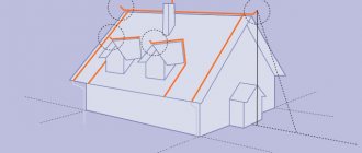
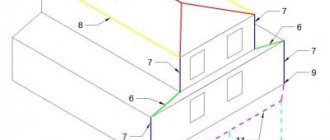
Blueprints. Roof and façade plans with designation of lightning rod protection zones (including at different elevations), installation diagrams of lightning rods, down conductors and grounding systems, designs of individual units.
Composition and content of text documentation of the EOM section
According to current standards, this subsection includes the following main documents:
- description and characteristics of external electrical networks with which the construction site will be connected, in accordance with the Technical Specifications (hereinafter referred to as TU). The note indicates: the number assigned to the technical specifications, the name of the organization that issued the document, the date of issue, the reliability category, the connection point;
Technical indicators are presented in the form of a table, an example of which is shown below:
| № | Name | Unit Change | Magnitude |
| 1 | Rated supply voltage | kV | 10/0,4 |
| 2 | Rated supply voltage of the distribution network | IN | 220/380 |
| 3 | Total installed capacity of low-voltage equipment | kW | 774,5 |
| 4 | Total installed lighting power | kW | 8,5 |
| 5 | Electricity consumption per year | MW x hour | 1345,2 |
- justification explaining the choice of the presented power supply scheme. It can be radial, mainline or mixed. The choice of one scheme or another depends on the category of consumer;
- list of electrical equipment and calculation of power for it (table for filling out the display below);
- indication of the power supply category, solutions for normal and emergency modes;
- information about the backup and additional power source (if any);
- recommendations and measures to reduce electrical energy consumption;
- type and class of protection of electrical equipment, including lighting fixtures, sockets, switches and wires, laying of routes (for example, in trays, corrugated pipes, etc.);
- information about emergency and normal lighting, indications of the type of gasket. As a rule, the lines of these types of lighting are laid separately from each other; this must be reflected in the explanatory note. For example, indicate that wiring is carried out in separate trays, boxes, etc.
A table for entering information about the quantity of electrical equipment, and its installed and calculated power.
Documentation for industrial facilities may additionally include a description of systems that allow compensation for reactive power, automation and control, including information about the organization of work of the dispatch service, as well as other information, in accordance with regulatory standards. documents.
Initial data for design
To begin, the designer needs to collect the following information and obtain the necessary drawings from the customer:
- general plan of the facility (all structures that need to be protected, as well as infrastructure, technological lines, ground and underground communications, pipelines, telecommunication channels, electrical and low current, etc.) (if it is necessary to protect several buildings or take into account the proximity of others)
- separate drawings (plans) of the roof and facades of the building with a list of materials used in construction, including the presence and materials of the drainage system
- other drawings necessary for the calculation as part of the construction and architectural parts, the presence and overall dimensions of roof superstructures
- the purpose of the object, the degree of presence of people in it
- climatic conditions of the area, zone of thunderstorm activity
- soil characteristics (soil type, groundwater level)
Differences between isolated and non-insulated options
The down conductors themselves, like the holders, can also be divided into two groups:
- non-insulated;
- isolated.
The latter are considered a more modern solution than the former. Non-insulated products are characterized by the fact that they connect all metal parts of the lightning protection system. This allows you to reduce the potential difference during a lightning strike.
But communication antennas, satellite dishes, and other data transmission equipment remain unprotected with this approach. And this problem is solved by an insulated down conductor. It can provide the required distance between metal elements (so-called air insulation). Moreover, these elements and the building body will no longer be in danger of inducing potentials.
Today, the effectiveness of insulated systems is no longer in doubt - they are successfully installed on various buildings and masts around the world.
A specific example here is the iscon 750 sw insulated down conductor.
This is a product from the German company OBO Bettermann. It provides a separation distance of 750 millimeters (as is clear from the number in the name). Its surface has no sliding discharge and is resistant to high voltage. This down conductor is available in two variations - one is suitable for laying in the ground, and the other on the surface.
Design stages
Preliminary selection (concept development):
- Determination of the lightning protection category of an object. According to regulatory documents RD 34.21.122-87 or SO 153-34.21.122-2003, we select the lightning protection class (I, II, III or IV);
- Selecting a lightning protection method (protective angle, rolling sphere or mesh) and type of grounding loop (focal, ring or foundation);
- Choice of material for system elements. Based on standards, taking into account aesthetic and economic considerations, as well as installation and environmental features (the most common are Al, Cu, galvanized or stainless steel);
- Determining locations for installing lightning rods and laying down conductors.
Equipment calculation:
- Lightning protection equipment - calculation of protection zones, selection of lightning protection system (rod, cable lightning rods or mesh, as well as their combination), determination of their diameters and lengths;
- Down conductors (calculation of quantity and diameter);
- Calculation of the number and installation locations of roofing and facade holders;
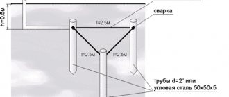
- Calculation of the ground loop.
Service for calculating the probability of a lightning strike on an object
You can use a unique service for calculating the probability of a lightning strike into an object protected by lightning rods, developed by the ZANDZ team together with JSC Energy Institute named after G.M. Krzhizhanovsky (JSC ENIN)
This tool allows you not only to check the reliability of the lightning protection system, but also to carry out the most rational and correct lightning protection design, providing:
- lower cost of design and installation work, reducing unnecessary stock and using smaller lightning rods that are less expensive to install;
- fewer lightning strikes into the system, reducing secondary negative consequences, which is especially important in facilities with many electronic devices (the number of lightning strikes decreases with decreasing height of lightning rods).
The functionality of the service allows you to calculate the effectiveness of the planned lightning protection in the form of understandable parameters:
- the probability of a lightning breakthrough into system objects (the reliability of the protection system is defined as 1 minus the probability value);
- number of lightning strikes into the system per year;
- number of lightning breakthroughs bypassing protection per year.
Having such information, the designer can compare customer requirements and regulatory documentation with the obtained reliability and take measures to change the lightning protection design.
To start calculating, follow the link.