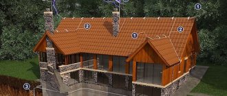
Lightning protection systems should be checked for functionality from time to time. The need for such tests is dictated by ensuring the safety of both the building and the people in it. In addition, lightning rods are under constant negative influence of environmental factors, which can lead to a deterioration in their functionality.
Checking lightning protection is an important event that is carried out as planned or unscheduled if there are doubts about the operability of the system.
Types and frequency of inspections
Verification activities are usually divided into types:
- Scheduled inspection (another name is seasonal). Conducted according to a predetermined schedule.
- Extraordinary inspection. Carried out in the event of unforeseen events (for example, system failure).
- Start-up and introductory testing of protection.
Scheduled tests
The procedure for conducting scheduled testing is regulated by the standards established in instructions RD-34.22.121-87. Inspections are regulated by the provisions of the PUE (rules for the construction of electrical installations) and PTEEP (rules for the technical operation of consumer electrical installations). For outdoor protective devices, the rules are specified in paragraph 1.14 of RD-34.22.121-87.
In accordance with these standards, all protected objects are divided into categories. Based on the category established for the building or structure, the frequency of inspection of the lightning protection system is established. For example, for buildings of the first and second categories, tests should be carried out every year before the onset of thunderstorm season. The third category concerns objects exposed to minor danger. In this case, inspections should be carried out every three years.
Extraordinary tests
Inspections outside the planned schedule are carried out in the following cases:
- Making any changes to structural elements that were not initially included in the design documentation.
- Upon completion of repair work and reconstruction of the building.
- In the event of major accidents, catastrophes or natural disasters.
Start-up and introductory tests
They are carried out upon delivery of the protected building to the customer. Start-up testing is carried out immediately after completion of the main construction work or according to a previously agreed schedule for the reconstruction of the facility.
The results of the inspection are documented. Based on the conclusion, operation of the system begins.
Lightning protection systems are tested:
- before putting them into operation
- for buildings and structures of protection category I and II at least once a year
- for buildings and structures of protection category III at least once every 3 years
At the same time, monitoring of the transient resistance of bolted connections of lightning protection systems should be carried out annually with the beginning of the thunderstorm season.
Lightning protection devices for buildings and structures must be tested, accepted and put into operation before finishing work begins.
Stages of inspections
The task of scheduled, introductory and extraordinary resistance measurements and checks of lightning protection devices according to other parameters is to assess the compliance of the existing parameters with the regulations and design documents. For this purpose, the quality of installation work is examined, the condition of local sections of the system and contacts is determined. The goals of testing, the content and scope of tasks depend on the parameters of the object and the design features of the protection system.
Tests are carried out according to a certain algorithm:
- Compare the data available in the design documentation with real indicators.
- They check the compliance of protective zones and structures with the requirements of regulatory documents.
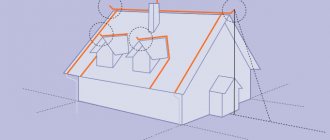
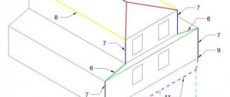
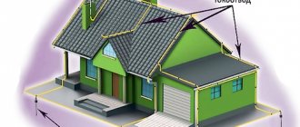
- Inspect protective devices, down conductors, and connecting contacts to check their integrity, the absence of traces of rust, and the quality of installation connections.
- Welds are checked for integrity and strength by applying mechanical forces (tapping with a hammer).
- Measure the resistance of bolted joints.
Measurements of the grounding resistance coefficient of lightning rods are carried out separately for each device. The final indicator should differ no more than five times from the data obtained during the introductory tests. If the grounding conductor performs a related task (working grounding conductor of the building and lightning protection system), there is no need for resistance measurements.
To obtain the most accurate results, planned and start-up testing work is carried out during the lowest level of moisture in the soil adjacent to the building. In regions belonging to permafrost zones, measurements are carried out during the period of maximum freezing of the ground.
Note! When testing the system, the level of atmospheric pressure is taken into account. This parameter is secondary, but is included in the final protocol.
Technical events
The list of necessary technical measures is determined by the person who allows the work together with the manufacturer in accordance with the requirements of SNiP 12-03-99.
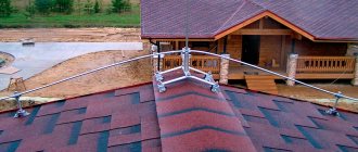
When inspecting and checking the condition of lightning rods and down conductors on the roofs of buildings and structures, it is necessary to use installer safety belts. If the length of the belt sling is insufficient, it is necessary to use a safety rope previously secured to the building structure. In this case, one of the persons conducting the tests slowly lowers or tightens the safety rope. When checking welded joints of external current conductors and the design of lightning rods, the tool (hammer) must be tied to avoid falling. When a thunderstorm approaches, all work must be stopped and the team removed from the workplace.
Standardized values
Protection against direct lightning strikes of buildings and structures classified as category I according to lightning protection devices must be carried out using free-standing rod or cable lightning rods
Protection against direct lightning strikes of buildings and structures classified as lightning protection categories II and III, with a non-metallic roof, must be carried out by separate rod or cable lightning rods or installed on the protected object.
When the roof slope is no more than 1:8, a lightning rod can be used as a lightning rod, made of steel wire with a diameter of at least 6 mm with a cell pitch for protection category II of no more than 6x6 m and 12x12 m for II I laid to grounding conductors no less than through 25 m along the perimeter of the building, they should be located no closer than 3 m from the entrances to buildings and in places inaccessible to the touch of people and animals. protection categories. Down conductors from a metal roof or lightning protection mesh must be
In all of the above cases, reinforced concrete building foundations should additionally be used as natural grounding conductors for lightning protection systems.
The dimensions of lightning rods, down conductors and grounding elements are given in Table 1.
TABLE 1.
| Shape of lightning rods, down conductors | Outside | In the ground |
| Rod lightning rods (steel) - cross-section no less - length not less | 100 mm2 200 mm | — — |
| Cable lightning rods (multi-wire steel rope) - cross-section no less - length | 35 mm2 depending on the protection zone | — — |
| Round down conductors and jumpers (steel) - diameter not less | 6 mm | — |
| Round vertical electrodes (steel) - diameter not less | — | 10 mm |
| Round horizontal electrodes (steel) *—diameter no less | — | 10 mm |
| Rectangular down conductors and grounding conductors (steel) - cross-section no less - thickness not less | 48 mm2 4 mm | 160 mm2 4 mm |
*Only for equalizing potentials inside buildings and for laying external contours at the bottom of the pit along the perimeter of the building. Connections of lightning rods with down conductors and down conductors with grounding conductors must be made by welding, and if hot work is not allowed, by bolted connections with a transition resistance of no more than 0.05 Ohm. Welds should not have cracks, burns, lack of penetration of more than 10% of the length of the seam, unfilled craters and undercuts. The surface of the seam should be uniformly scaly, without sagging. The length of the weld must be: for a design of round sections at least 6d (d is the diameter of the lightning rod, down conductor, grounding conductor), rectangular - 2 V, where B is the width of the steel strip of lightning protection system structures (clause 3.2 of VSN 164-82, GOST 10434-82, SNiP Sh-33-76 section II).
Measuring equipment
High-precision equipment type M-416 is used for testing. The device is used in conjunction with a data meter for electrical safety of equipment and electrical installations (MPI-511). At the same time, existing standards allow the use of other measuring instruments with similar capabilities.
The resistance of the functional elements of the protective system is measured with the MRU-101 device. The device is capable of automatically stopping the test when emergency situations occur and displays the following indicators on the monitor:
- Overcoming 24V noise level (LIMIT and UN).
- Noise voltage exceeds 40B (LIMIT and OFL).
- No current current (-r- and test socket icon).
- The resistance level of the measuring probes is too high - over 50 kOhm (LIMIT and indicator on the probe).
- The meters exceed the standard range (OFL).
The noise voltage indicator is set by pressing the R button or by selecting the measurement function by turning the device switch.
The received data is not considered correct if the equipment has detected the following situations:
- Deviation of the resistance level of the probes by 30% (LIMIT).
- The battery is in a discharged state (BAT).
If there are no grounds for blocking or slight deviations of the input data from the standards, MTU-101 takes measurements and displays the following data:
- The amount of resistance in a given area.
- Probe resistance.
- Soil resistivity.
- Other indicators (for more information, press the SEL button).
Note! The measurement range for each parameter is determined automatically by the equipment.
Conditions for the examination
Scheduled tests are carried out before the start of the thunderstorm season. A visual inspection of the external lightning protection elements of an object should be carried out in clear, dry weather with low or normal relative air humidity.
Measurement of the resistance of the system's grounding loops during introductory and routine checks is carried out in conditions where the soil has the greatest electrical resistance in order to obtain maximum accuracy and reliability of the measurement results. Such conditions climatically correspond to moments of deep freezing in winter or the driest periods in spring and summer.
Three-pole measuring system
For measuring the resistance of a lightning protection system, the method is considered basic. The work is carried out as follows:
- The ground electrode is connected to the measuring socket of the equipment.
- The current probe is directed into the ground. The measurement is carried out at a distance of over 40 meters from the protective system. The probe is connected with a special conductor to the socket of the device called “H”.
- The potential probe is installed in the ground at a distance of more than 20 meters from the protective system being studied. Next, the probe is connected to the measuring socket marked with the letter S.
- The probes and the ground electrode are lined up in a single line.
The rotary switch is placed in position RE 3p. Next, measurements begin after pressing the START key.
After the procedure is completed, the ground resistance indicator (RE) and the data obtained from the probes appear on the monitor. The distance between the potential probe and the protective system is reduced to one meter. Then they take another measurement. If the results differ by more than 3%, the current probe is moved further away. The measurement is carried out repeatedly until an acceptable ratio of the obtained data is obtained.
Measurements using a three-pole circuit involve taking into account several nuances. For example, with increased resistance of the probes, this indicator for grounding is set with a certain error. The same should be said about measurements of the resistance of the ground loop, which is in free contact with the ground. The reason for the existing errors is the excessively high ratio of the resistance of the probes and the ground electrode.
To improve the accuracy of the data obtained, it is necessary to achieve better contact of the probes with the ground. For this purpose, the probes are moved to another, more humid place. An alternative to this solution is to artificially moisten the soil before performing the test. In addition, you need to inspect the measuring conductors to ensure the integrity of the insulating material, the absence of traces of rust, and check the contacts with the probe terminals.
Note! The results of all additional procedures are recorded in the final protocol.
Compliance with all recommended conditions allows you to obtain fairly accurate results (taking into account the general measurement error). It should be borne in mind that a correct assessment of the influence of the resistance of the probes requires additional calculations.
Let's sum it up
All values collected during the inspection must be recorded in the test report. This document officially confirms the procedure performed. The conditions for conducting the study are also recorded without fail. All measurement activities are aimed at verifying the ability of the lightning protection system to fulfill its intended purpose. The basic values of all indicators that are used during the inspection are contained in GOSTs and standards.
Therefore, it is better to entrust the creation and maintenance of such systems to professionals - a licensed electrical laboratory with qualified personnel using certified electrical measuring instruments.
One of these professionals is the electrical engineering laboratory (ETL) Mega.ru, which provides a wide range of services to organizations and individuals in Moscow, the Moscow region, as well as surrounding areas. You can order work, get advice or clarify details of cooperation by calling the phone numbers and e-mails published on the “Contacts” page, or simply use the feedback form in the side column of the site.
Four-pole measurements
If particularly high accuracy of results is required, errors must be eliminated. Using a four-pole circuit will help in this matter.
Measurements are carried out as follows:
- The receiver is connected to the equipment sockets marked E and ES.
- Both probes are installed in the same way as in the three-pole method.
- The rotary switch is directed to position RE 4p.
- Press the START button.
- Record the obtained data on the grounding resistance and probes (Rs and RH). The data is displayed on the monitor.
The measuring probe is moved one meter from the protective system. After this, measurements are made again. The results obtained are interpreted in the same way as in the case of using a three-pole system. At the end of the study, the data is entered into the final protocol.
Note! Regardless of the scheme used, the norm is considered to be a distance of the potential probe to a value equal to 62% of the distance between the system under study and the current probe.
Measuring instruments
The installation quality of the lightning protection system is checked using special measuring equipment. This category includes both manually adjusted and automatically adjusted measuring equipment. In this area, priority is given to modern automatic meters, while manual devices are considered less reliable and outdated technology.
Among the self-tuning meters used for testing lightning protection systems, the most used is the MRU-101 device. It can be used to control resistivity, grounding resistance parameters, as well as characteristics such as spreading current. The device can store hundreds of measurement indicators in memory and selects a range that includes the desired settings.
The obvious advantages of this device include the indication of a potential error in the readings - in such a situation it gives a special signal. In addition, using the MRU-101, you can constantly monitor measurement conditions and noise levels: if an obvious error is detected, the measurement process will stop completely.
Operation of the device. The most common test method choice with the MRU-101 is the 3-pole circuit. In this case, three probes are driven into the ground in the area where the grounding components are located at a distance of up to 20 meters from each other. Then the working inputs of the device (E, H and S) are connected to the probes.
Another, more accurate method is to use a 4-pole circuit. Its difference from the above-described circuit is the connection of the electrode connected to the input marked “E” to the input wire marked “ES”.
Non-contact measurement technology. Measurements using MRU-101 can also be carried out non-contactly - for this purpose, special pliers are used, which are supplied with the device. Before use, the clamps are calibrated and then connected to the fifth input.
Documenting results
The main document indicating the reliability of the data obtained is the test report of the protective system. This document shows all the required performance characteristics. Separate paragraphs indicate the results of the measurements obtained and indicate the test conditions.
During introductory testing, working passports are issued. When the tests are completed, the owner of the object or his authorized representative is given documents indicating the results of the test.
Checking the lightning protection system is a critically important activity. The lives of people and the safety of material assets depend on how well the work is done. To carry out the inspection, it is recommended to contact reliable service providers who specialize in this type of work and have a good reputation.
Test facilities and equipment
The list of necessary testing tools and equipment is determined by the permitter together with the manufacturer of the work. In general, a set of devices, tools, and protective equipment should include the following:
- assembly line safety belts, safety ropes, safety helmets, ladders;
- device MRU-101
- hammer (weight 400 gr.)
- calipers
- tape measure 3 m
Safe working practices
Work on checking lightning protection systems of buildings is carried out according to a permit or by order. The type of work registration is determined by the employee who has the right to issue orders and orders. Persons from electrical technical personnel who are at least 18 years old, trained and certified in knowledge of safety regulations, PTEEP and this technique, provided with tools, personal protective equipment, and special clothing are allowed to work.
The team must consist of at least two people:
- a work performer with an electrical safety group of at least III
- a member of a team with an electrical safety group of at least III
These persons must undergo a medical examination for admission to steeplejack work and a knowledge test of SNiP 12-03-99 in the scope of the safety requirements for steeplejack work. A special entry is made about permission to carry out steeplejack work in the knowledge test log and in the certificate of verification of values on the page “Certificate for the right to carry out special work.”
Based on the measurement results, a protocol of the established form is drawn up. Persons who have committed violations of safety regulations or PTEEP, as well as those who have distorted the reliability and accuracy of measurements, are liable in accordance with the legislation and regulations on the mobile electrical laboratory.
Ground resistance
When measuring ground resistance for electrical installations, power frequency current is usually used. But when carrying out measurements for grounding lightning protection, the situation is fundamentally different. Measuring resistance for a short powerful pulse gives different results from measuring with alternating current. At the same time, the pulse method is closer to the real situation that occurs during a lightning strike. Numerous experiments have shown that the higher the current during pulsed action, the lower the soil resistance. In turn, we cannot predict in advance how strong a lightning strike will be. In addition, the duration of the pulse front has a greater influence on the accuracy of simulating real conditions during a lightning strike than the current value.
It can be concluded that it is permissible to measure grounding resistance using the pulse method at a current that is significantly lower than what occurs during a real lightning strike. In practice, pulses with currents of up to 1 A are used. But the measuring device must necessarily produce a pulse with a rise time that lies within this parameter for real conditions. The corresponding values of the pulse front duration are given in SO 153-34.21.122-2003. As a result of carrying out measurements using this technique, we obtain a slightly higher value of grounding resistance than with a real lightning strike, due to the lower current. That is, measuring at a lower current actually places more stringent requirements on grounding compared to testing with a generator that fully simulates a lightning strike.
When are tests carried out?
The frequency of maintenance of lightning protection devices is regulated by instruction RD-34.22.121-87, as well as the provisions of PUE, PTEEP and departmental standards. Regardless of the type of object being equipped and the composition of the protective complex, the latter must undergo a comprehensive check immediately before commissioning. The event is carried out in parallel with the main construction and installation work or in accordance with the schedule for reconstruction/re-equipment of the facility.
As a rule, an introductory inspection is scheduled before the main finishing work, and when protecting objects with explosive zones - before comprehensive testing of technological equipment. Otherwise, calculations based on measurement results must be supplemented with correction factors. The same applies to technical solutions for lightning protection of unique objects or those located in special climatic or seismically active zones. Based on the results of the study, an act is drawn up, which is the basis for putting lightning rods into operation.
For a working lightning protection system, the frequency of inspections is determined in accordance with clause 1.14 of RD 34.21.122-87:
- for objects of categories I and II – annually before the start of the thunderstorm season;
- for category III objects - at least once every 3 years of operation.
Similar to objects of categories I and II, once a year before the start of the thunderstorm season, medical objects are inspected and tested for protection against lightning and lightning electromagnetic phenomena. The event may include specific tests, based on the results of which a separate report is drawn up.
Classification of objects is carried out by type and purpose, territorial location and type of protection zone. The list of buildings and structures, utilities and technological installations subject to lightning protection and recommendations for equipping them with protection of one or another category are given in Table 1 of RD 34.21.122-87.
For the greatest accuracy and reliability of the results, introductory and scheduled periodic checks of the grounding devices of the protective system are carried out during the driest periods or when the soil is deeply frozen, when the latter provides maximum resistance. Inspection of the external elements of the system is carried out in clear weather with normal or low relative humidity.
Extraordinary inspections of lightning protection devices are assigned:
- when making any changes to the technical solution for lightning protection;
- after repair or reconstruction in accordance with the requirements of previous inspections;
- during reconstruction, re-equipment of a facility or its restoration from damage received as a result of accidents, catastrophes and natural disasters.
If the lightning protection of an object consists of several lightning rods, their condition is checked separately.
One of the main lightning rod devices is a ground loop. According to the requirements of the PUE, it must be checked:
- 1 time every 6 months – visually;
- Once every 12 years - with selective opening of the soil.
The resistance of the ground loop is measured:
- Once every 6 years - on power lines with voltage up to 1 kV;
- Once every 12 years - on power lines with voltages over 1 kV.
The complex nature of protecting an object from lightning discharges and spontaneous electromagnetic pulses, the presence of special conditions at the object, the presence of specific natural factors, as well as the multi-tasking nature of the inspection itself imply the possibility of carrying out its various stages in certain areas of the system outside of regulatory schedules with the preparation of appropriate acts and protocols.
The importance of checking lightning protection
The need to check lightning protection is due to the fact that over time the operating parameters of the system may deteriorate. Electrical connections break, resistance increases, corrosion formations and mechanical damage appear. It is impossible to detect violations in the protective properties by visual inspection alone, therefore there are special methods for testing lightning protection, as well as methods for testing RCDs. We will talk about the essence of these techniques and their frequency here.
Measures to maintain performance
Based on the results of the inspection, a protocol and a list of defects are drawn up. They include data on all deficiencies and identified deficiencies. Faults that interfere with the operation of lightning protection must be corrected as quickly as possible.
Faulty parts, as well as grounding elements whose cross-sectional area has decreased by more than 25% due to corrosion, must be replaced. To prevent corrosion, anti-corrosion agents should be regularly applied to the lightning rod elements that require such treatment. Such means, in particular, are suitable paints and varnishes.