- home
- >Manufacture of generators
Hello, people often write to me about how best to make an axial disk generator, how many magnets there should be and how many coils. They ask what wire the coils should be wound with and how many turns. They ask about the ratio of magnets to coils, and how to connect the coils to each other. I will try to answer these questions, accompanying them with drawings...
>
Windmill with axial generator on neodymium magnets
The strongest magnets with optimal parameters for use in generator design are neodymium magnets. They are somewhat more expensive than conventional ones, but they are many times superior and make it possible to create a powerful device in a relatively compact size.
There is no fundamental difference in the design. Neodymium magnets are manufactured in various form factors, allowing you to choose the most convenient option for yourself - thin oblong bars, tablet shape, cylinders, etc. if a metal rotor is used, then it is not necessary to glue the magnets; they themselves are attached to the base with force. All that remains is to fill them with epoxy to protect them from corrosion.
Wind generator on neodymium magnets with a power of 5.0 kW
Currently, domestic and foreign companies are increasingly using neodymium magnets in the manufacture of low-speed electric current generators. Thus, Salmabash LLC, Gatchina, Leningrad Region, produces similar permanent magnet generators with a power of 3.0-5.0 kW. The appearance of this device is shown below:
The generator housing and covers are made of steel, later coated with paint and varnish materials. The housing is equipped with special fastenings that allow you to secure the electrical device to the supporting mast. The inner surface is treated with a protective coating that prevents metal corrosion.
The generator stator is made of electrical steel plates.
The stator winding is made of enamel wire, allowing the device to operate for a long time at maximum load.
The generator rotor has 18 poles and is mounted in bearing supports. Neodymium magnets are placed on the rotor rim.
The generator does not require forced cooling, which is carried out naturally.
Technical characteristics of the 5.0 kW generator:
- Rated power – 5.0 kW;
- Rated frequency – 140.0 rpm;
- Operating rotation range – 50.0 – 200.0 rpm;
- Maximum frequency – 300.0 rpm;
- Efficiency – not less than 94.0%;
- Cooling – air;
- Weight – 240.0 kg.
The generator is equipped with a terminal box through which it is connected to the electrical network. The protection class corresponds to GOST 14254 and has a degree of IP 65 (dust-proof design with protection from jets of water).
The design of this generator is shown in the figure below:
where: 1-body, 2-bottom cover, 3-top cover, 4-rotor, 5-neodymium magnets, 6-stator, 7-winding, 8-coupling half, 9-seals, 10,11,12-bearings, 13 - terminal box.
How to make a perpetual motion machine
Homemade generators with neodymium magnets are basically the same type in terms of their operating principle. The standard option is the axial type.
It is based on a car hub with brake discs. Such a base will become reliable and powerful.
When deciding to use it, the hub should be completely disassembled and checked to see if there is enough lubrication, and if necessary, clean off the rust. Then the finished device will be pleasant to paint, and it will take on a “homey”, well-groomed appearance.
Magnets are glued to the rotor discs. The author of the design presented in the photo in the article took twenty pieces measuring 25*8 millimeters. A different number of poles can be used.
In a single-phase device, the number of poles must be equal to the number of magnets. In three-phase, the ratio of two to three or four to three must be observed. Magnets are placed with alternating poles. They must be precisely located. To do this, you can draw a template on paper, cut it out and accurately transfer it to the disk.
To avoid mixing up the poles, make notes with a marker. To do this, magnets are brought on one side: the one that attracts is designated with a “+” sign, and the one that repels is marked with a “-”. Magnets must attract, that is, those located opposite each other must have different poles.
Usually superglue or something similar is used, and after sticking it is filled with more epoxy resin to increase strength, after making “borders” so that it does not leak out.
Phases - which is better - three or one?
Many lovers of electrical equipment follow the path of least resistance and, in order not to bother, opt for a single-phase stator for a windmill. However, it has one unpleasant feature that neutralizes the ease of assembly - vibration when loaded, due to the variability of current output. After all, the amplitude of such a stator is abrupt, reaching a maximum when neodymium magnets are located above the coils, and then dropping to a minimum.
But when the generator is made using a three-phase system, there are no vibrations, and the power indicator of the windmill has a constant value. The reason for this difference is that the current, falling in one phase, at the same time increases in the other. As a result, a wind generator operating in a three-phase system can be up to 50% more efficient than the exact same one using a single-phase system. And most importantly, a loaded three-phase generator does not produce vibration, therefore, the mast does not give rise to complaints about the wind generator to the supervisory authorities from ill-wishers among neighbors, since it does not create an annoying hum.
Alternating single-phase and three-phase electric current
Electric current is the directed movement of electrically charged particles under the influence of an electric field (Appendix, Fig. 1). Such particles can be: in conductors - electrons, in electrolytes - ions (cations and anions). In the theory of electrical circuits, current is considered to be the directional movement of charge carriers in a conducting medium under the influence of an electric field. Conduction current is the amount of electricity flowing per unit time through the cross section of a conductor:
i=q/t,
where i is current (A), q = 1.6·109 is electron charge (C), t is time (s).
But this expression is valid only for DC circuits. For alternating current circuits, the so-called instantaneous current value is used, equal to the rate of change of charge over time:
i(t)= dq/dt.
An electric current is called alternating if it changes its direction over a certain time and continuously changes in magnitude. The value of alternating current varies according to a sinusoidal law (Appendix, Fig. 2):
i = Im sin (2πft),
Where; i – instantaneous current value, Im – amplitude or maximum current value, f – alternating current frequency value, t – time.
Alternating current is widely used due to the fact that alternating current electricity can be technically simply and economically converted from lower voltage energy to higher voltage energy and vice versa. This property of alternating current allows electricity to be transmitted through wires over long distances.
Industrial alternating electric current is obtained using electric generators, the operating principle of which is based on the law of electromagnetic induction. The rotation of the generator is carried out by some energy source.
Alternating single-phase electric current has the following main characteristics:
f – frequency of alternating current determines the number of cycles or periods per unit of time. The unit of measurement of alternating current frequency is Hertz (Hz) (1Hz = 10-3kHz = 10-6mHz);
Τ – period – time of one complete change of a variable value (if 1 period Τ occurs in 1 second, then frequency f = 1 Hz);
ω – angular velocity equal to – ω=2πf;
The current strength at individual moments when it changes along a sinusoid is called instantaneous current values. The largest instantaneous value of a single-phase alternating current when it changes along a sinusoid is called amplitude. Currently, the three-phase alternating current system is most widespread throughout the world. A three-phase system of electrical circuits is a system consisting of three circuits in which alternating electromotive forces of the same frequency act, shifted in phase relative to each other by 1/3 of the period (φ = 2π/3) (Appendix, Fig. 3) . Each individual circuit of such a system is briefly called its phase, and the system of three phase-shifted alternating currents in such circuits is simply called three-phase current.
DIY low-speed permanent magnet generator
The secret of Perendeva's magnetic generator. Do it yourself
Good evening everyone, my father and I have been puzzling over the famous Perendev engine for a long time, we tried many options, we had one engine, the essence of which was to place magnets on the rotor as tightly as possible and all with one pole outward, and on the stator to place three poles of magnets that will be shifted away from each other (in general, what Perendev did with three disks):
Here is a good article about the robotic principle of the Perendev engine, which gives answers to many questions.
Upon careful study of the perendev patent (the link to the patent is on the Russian page, the entrance is from the German site), a drawing of the actual “single element” was discovered, that is, a shielded magnet.
Judging by the drawing, the cylindrical magnet is located inside not just a thick-walled iron cylinder, but inside a cylinder with a ring of metal added at the end.
Thus, the edges of the magnet (with maximum magnetic fluxes) are hidden in the iron. Only the platform in .
Apparently, to test the principle, it is enough to simulate several variants of a single element - take into account the geometry of the cylinder shown in the patent, and make it from stainless steel (as the author claims) and from ordinary soft magnetic iron. Most likely, the magnet itself must be held inside the cylinder by some kind of insulator ring so that it does not come into contact with the iron, otherwise the cylinder will be magnetized with all the consequences. As for graphite, according to the author, I doubt that the combination of stainless steel with graphite in any geometric positions could even partially shield the magnet.
However, you can try to check this too. I checked with a regular stainless steel cylinder with a tablet inside, there is no shielding.
——————————— In an interview, Brady found the phrase that all magnets are cut into a cone, insulated with a layer and inserted into shielding cylinders.
The main idea is this: Let me explain without drawing. On fingers. Let's take a time period of 5 seconds (for simplicity). There are, say, 9 or 11 magnets on a cylindrical rotor. and on the stator, respectively, 8 or 10. In the first second, the 1st magnet of the rotor is at dead center. The maximum counteracting force = x acts on it. At this same second, magnet 2 has already passed its dead point and is pulling with some positive force. accordingly, No. 3 is also after the dead center, and also in the black. and so on until No. 9.
in the second second No. 2 enters the dead center, and everyone else in the same second second (or any other minimum unit of time) pulls with positive force, compensating for the dead center.
The point is that with different numbers of magnets in the stator and rotor, their arrangement should be such that at ANY moment in time there is ONLY ONE magnet in the MT, and all the others, the number of which cannot be less than a certain number, should be the total traction force to compensate for the passage of this single dead center. The number of magnets must be calculated in each specific case separately. One thing is certain: by definition, building a model with 3-5 magnets will not work. The number of rotors must be such that the sum of the rotor magnets located in different positions relative to the stator is GREATER than the dead center force for a single magnet, or, if you like, a rotor-stator pair suspended in the MT.
You just need to understand this principle. Perendev's three prototype rings will only create increased power to spin up a 20 kW generator (video). But each individual ring, or rather a pair, rotor-stator, has just such a balance of forces.
Of course, you need to very accurately position the magnets on the ring to meet this condition. and Perendev additives in the form of insulating iron cylinders simply remove the parasitic influence of magnets on each other, leaving this very principle in its bare form, since when approaching the MT, having a screen, the rotor magnet interacts only with its stator magnet, without feeling the parasitic fields of neighboring stator magnets and rotor. That is, the principle in its purest form. It is absolutely clear that such designs are possible only in cylindrical forms, however, the correctness of this statement of mine can also be verified on a linear model. To do this, the distances between the rotor magnets on the ruler must be greater by some amount than the distance between the stator magnets on the other ruler. But by no means equal. For example, you can place 30 magnets on a linear stator with an interval of 10 mm, and on a rotor ruler 9-11 magnets with an interval of 11 mm.
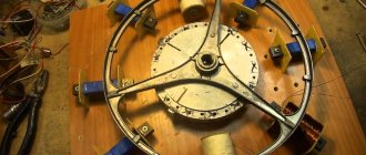
Rotor creation process
The magnets should be positioned taking into account the alternation of poles, and as accurately as possible, but before you start sticking them, you need to either create a paper template or draw lines dividing the disk into sectors. To avoid mixing up the poles, we make marks on the magnets. The main thing is to fulfill the following requirement: those magnets that stand opposite each other must be turned with different poles, that is, attract each other.
The magnets are glued to the disks using super glue and filled in. You also need to make borders along the edges of the disks and in their center, either by wrapping tape or molding them from plasticine to prevent spreading.
Modification of a car generator
Creating a permanent magnet rotor requires quite a serious intervention in the design. It is necessary to reduce the diameter by the thickness of the magnets plus the thickness of the steel sleeve, which is placed on the rotor to form a continuous magnetic flux and at the same time serves as a landing pad for the magnets. Some experts do without a sleeve, installing magnets directly on the rotor with a reduced diameter and fixing them with epoxy.
The manufacturing process requires the participation of production equipment. The rotor is clamped into the lathe and the layer is carefully removed so that the installed magnets rotate with minimal clearance, but quite freely. The magnets are installed on the rotor plates with alternating polarity.
Making a rotor from a hub and brake disc
The considered method applies to ready-made generators that require minor design changes. Such devices include car generators, which are often used by amateur designers as a basic device. Often, generators are assembled completely independently, without having a ready-made device.
In such cases, they act somewhat differently. The basis is a car hub with a brake disc. It is well-balanced, durable and adapted to certain types of loads. In addition, the size of the hub allows a large number of magnets to be placed around the circumference, allowing three-phase voltage to be obtained.
Magnets with alternating polarity are placed at a distance equidistant from the center. Obviously, the highest number can be set by gluing them as close to the outer edge as possible. The most accurate indicator will be the size of the magnets, which will determine the possibility of placement at a certain distance. The number of magnets must be even so that the rhythm of alternating poles during rotation does not break down.
Gluing magnets to the hub is done using any glue; the best option is epoxy resin, which is used to completely fill the magnets. This protects them from moisture or mechanical stress. Before pouring, it is recommended to make a plasticine rim along the edge of the hub to prevent the epoxy from flowing down from the hub.
The design of the generator on a car hub is most convenient when making a vertical windmill. It is noteworthy that a similar scheme can be used without a hub, on a disk cut from ordinary plywood. This design is much lighter, allows you to choose a convenient size, which makes it possible to create a sensitive and productive device.
Homemade generator for a windmill
How to make a low-speed generator for a windmill from neodymium magnets. Homemade generator for a windmill, diagrams, photos, videos.
To make a homemade windmill, you first need a generator, preferably a low-speed one. This is the main problem; finding such a generator is quite difficult. The first thing that comes to mind is to take a standard car generator, but all car generators are designed for high speeds, battery charging starts at 1000 rpm. If you install a self-generator on a windmill, it will be difficult to achieve such speeds; you will need to make an additional pulley with a belt or chain drive, all this complicates and makes the design heavier.
A windmill requires a low-speed generator; the best option is an axial type generator with neodymium magnets. Since there are practically no such generators on sale at an affordable price, you can make an axial generator yourself.
Homemade generator for a windmill made from neodymium magnets.
To make an axial type generator you will need:
- Car hub, brake discs.
- Neodymium magnets.
- Copper wire (0.7mm).
- Epoxy resin.
- Fastening elements.
An axial type generator for a windmill is shown in the diagram.
In this case, the stator will be a disk with coils, the rotor will be two disks with permanent magnets. When the rotor rotates, the current that we need to charge the batteries will be generated in the stator coils.
Homemade generator: making a stator.
The stator - the stationary part of the generator consists of coils that are placed opposite the rotor magnets. The internal size of the coils is usually equal to the external size of the magnets that are used in the rotor.
A simple device can be made for winding coils.
The thickness of the copper wire for the coils is approximately 0.7 mm, the number of turns in the coils must be counted individually, the total number of turns in all coils must be at least 1200.
The coils are placed on the stator; the coil terminals can be connected in two ways, depending on how many phases the generator will have.
A three-phase generator will be more efficient for a wind generator, so it is recommended to connect the coils in a star type.
To fix the coils to the stator, they are filled with epoxy resin. To do this, you need to make a mold for pouring from a piece of plywood so that the liquid resin does not spread, you need to make the sides from plasticine or a similar material. At this stage, it is necessary to provide lugs for attaching the stator.
It is important to get a perfectly flat plane, so before pouring the matrix with coils must be installed on a flat surface. Before pouring, the coils must be carefully checked with a multimeter and placed on the matrix in a circle in such a way that the rotor magnets are then opposite the coils.
Liquid epoxy resin is poured into the matrix to the level of the edge of the coils; before pouring, the mold must be lubricated with Vaseline.
When the resin has completely hardened, we disassemble the matrix and remove the finished stator with coils.
The stator is fixed to the generator housing using bolts or studs with nuts.
Homemade generator: making a rotor.
In this design, the rotor will be double-sided, the stator with coils will be in the middle between the rotating disks with magnets.
On each hub disk, magnets must be placed in a circle, alternating the poles in sequence.
When the rotor disks are installed, the magnets should be directed towards each other with different poles.
The magnets need to be glued to the disks with superglue and filled with epoxy resin, the top part of the magnets should remain uncovered.
Making a rotor for a homemade video generator.
To attach the stator to the wind generator, you need to make a metal base, the stator is attached to it using bolts or studs.
We assemble the entire structure, while you need to leave a minimum gap between the stator and the rotor; the smaller the gap, the more efficient the generator will generate energy. A diode bridge must be connected to the output of the coils.
As a result, you will get an axial generator using neodymium magnets. A homemade generator can operate at low speeds and still generate enough energy to charge batteries, which is important when installing a wind generator in areas where weak winds prevail.
Windmill generator video.
Electrical and technical parameters of the generator
The voltage is calculated using the formula:
Homemade generator
U=2*Ch*KP*KK*KV*MI*P, where:
- U – voltage in Volts;
- H – frequency of rotation of the generator rotor per second;
- KP – number of magnetic poles;
- КК – number of induction coils in the stator;
- KV – the number of turns of the conductor in one induction coil;
- MI is the magnetic induction in T, which is formed in a standard gap (2 mm);
- P – surface area of one neodymium magnet, in sq. m.
If simple coils are used, a magnetic induction of 0.5 Tesla is taken for calculation. When adding an electrical steel core, the value is increased to 0.7-0.9 T.
For your information. The formula is valid when connecting the windings in a triangle. If a three-phase generator is assembled using a star circuit, the resulting value is multiplied by a correction factor of 1.7.
After calculating the voltage, you need to find out the resistance in the windings. After this, it will be easy to determine the current and power. For a copper conductor, the resistivity is 0.0175 Ohm per mm2/meter. To calculate the total value, use the formula:
C= (US*D)/PP, where:
- C – resistance, in Ohm;
- US – resistivity of a certain material;
- D – conductor length in meters;
- PP – conductor cross-sectional area, mm sq.
To calculate the current, subtract the voltage of the battery connected for charging from the voltage of the magnetic generator at idle. The resulting value is divided by the resistance value calculated using the previous formula.
Increasing/decreasing the speed changes the current accordingly while keeping the voltage at the battery terminals constant. To calculate the performance of a wind turbine in different modes, use the standard formula:
P=I*U, where:
- P – power, Watt;
- I – current strength, Ampere;
- U – voltage, Volt.
How to increase the power of a windmill?
Magnets can be used to increase the power of a wind generator. Simply stick one more of the same or thinner magnets on the magnets that are already installed. Another method is based on installing metal cores, called transformer plates, into coils. This will ensure increased magnetic flux in the coil, but causes slight sticking, which, however, is not felt at all by the six-blade propeller. Such a wind generator starts at a wind of 2 m/s. Thanks to the use of cores, the generator received an increase in power from 300 to 500 W/h with a wind of 8 m/s. You should also pay attention to the shape of the blades - the slightest inaccuracies reduce power.
Manufacturing the stator of a three-phase alternating current generator
The generator stator is also made of 8 mm thick organic glass plates. In the plates, according to the markings, cavities are milled to accommodate 9 stator winding coils. The coils are wound with insulated copper wire D – 0.35 mm. Each coil holds the number of turns, according to the calculation data given above. The winding coils are glued into the grooves of the stator plates using sealant (Appendix, Fig. 13-15). Winding of all phase coils must be done in the same direction, marking the beginning and end of the winding. The connection of the coils of each phase is made according to the scheme: end - beginning. In total, three phase coils are placed on the stator plates, connected in series (Appendix, Fig. 16). The connection of all phase windings can be made in two ways: star and triangle (Appendix, Fig. 17 - 18). In our case, the connection is made by a star, including all stator plates. Current rectification is carried out by a three-phase rectifier made of semiconductor diodes (N4107) (Appendix, Fig. 18). The entire “sandwich” of the generator is assembled on a base made of organic glass. The stator plates are rigidly attached to the base with metal stands. The rotor plates are movably mounted on a bearing assembly from the disk drive motor. The axis of the bearing assembly passes through the entire generator and fastens the movable rotor plates (Appendix, Fig. 17).
Manufacturing a rotor for a three-phase alternating current generator
The rotor plates are made of organic glass 5 mm thick. Circles with a diameter of 95 mm were cut out of organic glass; according to the markings, 12 holes were drilled in them for neodymium magnets (D – 15 mm). Magnets with opposite poles were glued into the holes intended for them (Appendix sheet V, Fig. 12 - 13). Three such plates were made for the generator. The central plate, which is located between the stator plates, is made only of organic glass. Metal plates made of steel 1.5 mm thick are glued to the upper and lower rotor plates. Each plate contains 12 magnets, oriented along the poles.
Types of magnets
Permanent magnets are divided into 2 types:
- natural;
- artificial.
Natural
In nature, a natural permanent magnet is a fossil in the form of a fragment of iron ore. Magnetic rock (magnetite) has its own name in every nation. But in each name there is such a concept as “loving”, “attracting metal”. The name Magnitogorsk means the city's location next to mountain deposits of natural magnetite. For many decades, active mining of magnetic ore was carried out here. Today there is nothing left of Magnetic Mountain. This was the development and extraction of natural magnetite.
Until humanity achieved the proper level of scientific and technological progress, natural permanent magnets served for various fun and tricks.
Artificial
Artificial PMs are obtained by inducing an external magnetic field on various metals and their alloys. It was noticed that some materials retain the acquired field for a long time - they are called solid magnets. Materials that quickly lose the properties of permanent magnets are called soft magnets.
In factory production conditions, complex metal alloys are used. The structure of the Magnico alloy includes iron, nickel and cobalt. Alnico alloy contains aluminum instead of iron.
Products made from these alloys interact with powerful electromagnetic fields. As a result, quite powerful PMs are obtained.
Types and forms of PM
Advantages and disadvantages
The advantages of wind generators made using neodymium magnets include the following characteristics:
High efficiency of devices, achieved by minimizing friction losses;
- Long service life;
- No noise or vibration during operation;
- Reduced costs for installation and installation of equipment;
- Autonomy of operation, allowing operation without constant maintenance of the installation;
- Possibility of self-production.
The disadvantages of such devices include:
- Relatively high cost;
- Fragility. Under strong external influence (impact), a neodymium magnet can lose its properties;
- Low corrosion resistance, requiring special coating of neodymium magnets;
- Dependence on operating temperature – when exposed to high temperatures, neodymium magnets lose their properties.
Main characteristics
In order to determine the feasibility of manufacturing a generator using neodymium magnets, you need to consider the main characteristics of this material, which are:
- Magnetic induction B is a strength characteristic of a magnetic field, measured in Tesla.
- Residual magnetic induction Br is the magnetization possessed by a magnetic material when the external magnetic field strength is zero, measured in Tesla.
- Coercive magnetic force Hc - determines the resistance of a magnet to demagnetization, measured in Amperes/meter.
- Magnetic energy (BH)max - characterizes how strong the magnet is.
- Temperature coefficient of residual magnetic induction Tc of Br – determines the dependence of magnetic induction on the ambient temperature, measured as a percentage per degree Celsius.
- Maximum operating temperature Tmax - determines the temperature limit at which the magnet temporarily loses its magnetic properties, measured in degrees Celsius.
- Curie temperature Tcur - determines the temperature limit at which a neodymium magnet is completely demagnetized, measured in degrees Celsius.
The composition of neodymium magnets, in addition to neodymium, includes iron and boron and depending on their percentage, the resulting product, the finished magnet, differs in classes, differing in their characteristics given above. A total of 42 classes of neodymium magnets are produced.
The advantages of neodymium magnets that determine their demand are:
- Neodymium magnets have the highest magnetic parameters Br, Hsv, Hcm, VN.
- Such magnets have a lower cost compared to similar metals containing cobalt.
- They have the ability to operate without loss of magnetic characteristics in the temperature range from – 60 to + 240 degrees Celsius, with a Curie point of +310 degrees.
- From this material it is possible to make magnets of any shape and size (cylinders, disks, rings, balls, rods, cubes, etc.).
Advantages
Devices can be purchased ready-made or made independently. Having purchased a wind generator, all that remains is to install it. All adjustments and alignments have already been completed, tests have been carried out under various climatic conditions.
Neodymium magnets, which are used instead of a gearbox and bearings, allow you to achieve the following results:
- friction is reduced and the service life of all parts is increased;
- vibration and noise of the device during operation disappears;
- the cost decreases;
- energy is saved;
- There is no need to regularly service the device.
A wind generator can be purchased with a built-in inverter that charges the battery, as well as a controller.
Winding method for windmill stator coil
The coils should be wound with thicker wires if possible in order to reduce the resistance in them. This can be done on a mandrel or on a homemade machine.
In order to figure out what power potential the generator has, spin it with one coil, since, depending on how many neodymium magnets are installed and what their thickness is, this indicator may differ significantly. The measurements are carried out without load at the required number of revolutions. For example, if a generator at 200 rpm provides a voltage of 30 V, having a resistance of 3 ohms, then subtract 12 V (battery supply voltage) from 30 V and the resulting result is 18 divided by 3 (resistance in ohms) we get 6 ( current in amperes), which will go from the wind generator to charge the battery. However, as practice shows, due to losses in the wires and diode bridge, the actual indicator that the magnetic axial generator will produce will be less.
The thickness of the stator should be the same as the magnets. The form for it is usually plywood; for strength, fiberglass is placed under the coils and on top of them, and the whole thing is filled with epoxy resin. In order to prevent the resin from sticking to the mold, the latter is lubricated with any fat or adhesive tape is used. The wires are first brought out and fastened together, the ends of each phase are then connected with a triangle or an asterisk.
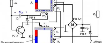
Magnetic generator
A magnetic motor is a truly free energy generator that can effectively replace a connection from a local electrical network, and does not require complex development, you just need to buy magnets. The Electricians Forum claims that in this way it is possible to create a silent current source.
Photo – Magnetic generator
It works on the principle of powerful neodymium permanent magnets. When the magnetic force reaches the required level to overcome the friction, the motor speed is directed to the ramps, the value reaches equilibrium. In a conventional motor, the magnetic field arises from electric coils, which are usually made of copper (Cu) and sometimes aluminum (Al).
Since copper and aluminum are not superconductors (their resistance is not zero), a conventional electric motor must continuously produce electricity to maintain the magnetic field and compensate for losses. This formation is difficult to operate due to high loss rates.
The magnetic design does not require self-induction coils, so it operates with virtually no losses. The magnet uses a constant magnetic field in which the force of a moving rotor is generated. The disadvantage of magnets is that it cannot control the flow. You won't be able to switch a magnet to a resistor or relay. But the advantages far outweigh the disadvantages:
- Low cost;
- Excellent performance indicators;
- There is virtually no energy loss.
Instructions for assembling a magnetic generator with photos
A practical model of this generator is easy to build yourself. All you need is a suitable set of neodymium magnets. Very small neodymium magnets can even be found in CD or DVD focusing systems.
The simplest homemade mechanical power generator is suitable for generating low to medium levels of free power. The maximum output value is significantly higher than the maximum of the electrical energy circuit. With a lighter design than an electromagnetic device, we get an analog asynchronous generator.
To generate useful electricity, there are two options:
- 1.Use coils of an electric motor as the basis of a magnetic motor. Such a home appliance is much simpler to design, but in this case the motor must have enough space for a set of magnets and winding coils (if necessary, winding is carried out independently) to operate on an imbalance.
- 2.Connect an electric generator to the magnetic motor. You can link the shafts directly or use a gear drive. The second version of the generator is capable of generating more energy, but it is difficult to design.
Let's consider an independent assembly method.
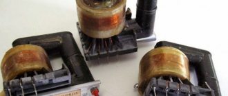
A computer fan can be used to create a small prototype magnetic free energy generator.
Photo - Computer radiator as an engine
Photo - Disassembled computer fan
Initially, coils are used to create a magnetic field. We can replace the coils with neodymium magnets. The magnets should be placed in the same directions as the original coils. This ensures that the orientation of the magnetic field required to operate the motor remains the same. In this motor, there are four coils, so four magnets must be used.
Photo - Coils Photo - Connecting neodymium magnets to a coil
The magnets are located in the direction of the coils. The engine runs due to the formed MP; it does not require electricity. By changing the direction of the magnets, you can change the speed of rotation of the motor, and accordingly its energy.
Photo - Correct placement of magnets
Photo - Rotation of magnets and operation of motors
These free energy generators are eternal; the engines will work until some magnet is removed from the circuit. If you assemble such a motor at home from a more powerful radiator, then there will be enough electricity to power a light bulb or even several household appliances (up to 3 kW), you just need to attach wires to the device that will transmit current to the electricity consumer.
Follow the news!
ps this article uses materials from Internet sources
How the devices work
The main problem of the design was considered to be the return of rotating parts to their original position without significant loss of torque. This problem was solved by using a copper conductor through which an electric current was passed, causing attraction. When the current was turned off, the attraction stopped. Thus, devices of this type used periodic on-off switching.
The increased current creates an increased attractive force, which, in turn, is involved in the generation of current passing through the copper conductor. As a result of cyclic actions, the device, in addition to performing mechanical work, begins to produce electric current, that is, perform the functions of a generator.
The nature of magnetism
The demonstration of the properties of a magnet in attracting metal objects to itself raises the question among people: what are permanent magnets? What is the nature of such a phenomenon as the occurrence of traction of metal objects towards magnetite?
The first explanation of the nature of magnetism was given in his hypothesis by the great scientist Ampere. Electric currents of varying degrees of strength flow in any matter. Otherwise they are called Ampere currents. Electrons, rotating around their own axis, also revolve around the nucleus of the atom. Thanks to this, elementary magnetic fields arise, which, interacting with each other, form the general field of matter.
In potential magnetites, in the absence of external influence, the fields of the atomic lattice elements are randomly oriented. An external magnetic field “arranges” the microfields of the material structure in a strictly defined direction. The potentials of opposite ends of magnetite repel each other. If you bring the identical poles of two strip PMs closer, then a person’s hands will feel resistance to movement. Different poles will tend to each other.
When steel or an iron alloy is placed in an external magnetic field, the internal fields of the metal are strictly oriented in one direction. As a result, the material acquires the properties of a permanent magnet (PM).
Magnetic generator from Korea - Infinity MG10
The developers of the MG10 magnetic energy generator position it as a system with a calculated and organized structure of the positions of magnets and bifilar coils. The operation of this structure is monitored by a controller operating under the control of a special program. This was done for the purpose of “correctly” turning on and “off” the coils (to suppress back EMF), which contributes to the efficiency of this device.
When a magnet passes relative to the coil, at the moment when the voltage in it is maximum, the controller “turns off” it, preventing the back EMF from braking the mechanism. This, as well as precise calculations of the angular alignment of magnets and coils, belong to the “know-how” of the mechanism.
The MG10 magnetic energy generator consists of sixty neodymium magnets and the same number of bifilar coils. The initial start-up of the device is carried out using the most common twelve-volt battery (which can be, for example, a car battery). The device allows the batteries to be recharged after each start.
The operation of MG10 does not depend on the external environment, wind, sun and other factors. After the generator has started and gained speed, the external source can be turned off: the device is completely autonomous.
Specifications of INFINITY MG10: generated current: 11.2A, effective output power 10KW, frequency 50/60Hz, can output single-phase: 110V/100A, 220-230V/50A, and three-phase current: 220-230V/16A, 380- 440V/16A.
Engine speed: 1500 rpm, dimensions 750x715x528 cm, weight 80 kg, operating noise does not exceed 60 dB, operating temperature range is from -40C to 70C. Service life 20 years. Recommended retail price: $15,000 (excluding VAT and customs duties).
In the absence of external influences, neodymium magnets remain “magnetic” for hundreds of years. Their demagnetization in the generator is extremely low: if the device is used properly, the demagnetization rate is approximately 1% every 10 years. If maintenance is performed regularly and promptly, the generator can last well beyond its 20-year guaranteed lifespan.
Conclusions and additional information
Using a gearbox and careful calculation of the blades, you can create a low-speed, low-noise, low-speed generator using neodymium magnets. Modern electronic components and corresponding circuitry will help create an inverter with high efficiency. New battery models perform their functions flawlessly, without routine maintenance, and retain their useful functions after hundreds of recharge cycles.
Wind generators with a vertical axis of rotor rotation
To get acquainted with existing installations, you can see the implemented projects of Sergei Savchenko, Alexander Sedov, Valery Yalovenko, Victor Burlak. Their ideas can be transformed taking into account personal capabilities and preferences. It’s easy to simplify calculations using specialized calculator programs that can be quickly found on the Internet. In any case, the magnetic generator should be considered in conjunction with other parts of the off-grid power supply system to ensure good coordination.
Conclusions and additional information
Using a gearbox and careful calculation of the blades, you can create a low-speed, low-noise, low-speed generator using neodymium magnets. Modern electronic components and corresponding circuitry will help create an inverter with high efficiency. New battery models perform their functions flawlessly, without routine maintenance, and retain their useful functions after hundreds of recharge cycles.
To get acquainted with existing installations, you can see the implemented projects of Sergei Savchenko, Alexander Sedov, Valery Yalovenko, Victor Burlak. Their ideas can be transformed taking into account personal capabilities and preferences. It’s easy to simplify calculations using specialized calculator programs that can be quickly found on the Internet. In any case, the magnetic generator should be considered in conjunction with other parts of the off-grid power supply system to ensure good coordination.