Thermocouples (TC) function in many thermal processes as primary temperature sensors of an automatic safety and control system. At household heat power facilities, they are installed to protect burners from flame separation on gas boilers, water heaters and stoves, for cooking.
They operate in the high-temperature zone of the gas torch, and therefore may fail. At the same time, the automatic safety system instantly turns off gas-using equipment. In order to ensure trouble-free and long-term operation of gas stoves, water heaters and boilers, it is necessary to exclude false triggering of the protection, and you also need to know how to test a thermocouple with a multimeter. This can be done at home without any problems.
What is a thermocouple?
The thermocouple design includes two dissimilar conductors that are in direct contact with each other at one or more points (in rare cases, they are connected by compensation wires). When a temperature change occurs in the sensor area, voltage is created inside the device.
This ensures temperature control and overheating protection. Thermocouples can also be used to convert thermal energy into other types of energy, including electric current.
The main characteristics of a thermoelectric converter directly depend on the material from which they are made. Any temperature sensor made from two different metals will produce an electrical potential when exposed to temperature, but the response temperature will be different for each combination of metals. Due to this, thermocouples differ in their level of temperature control.
There are many types of thermostats, but their resistance to corrosion will be important. In those models of thermoelectric converters where the temperature sensor is located at a sufficient distance from the measuring device, expansion wiring is used in the design to connect them, thereby reducing the cost of the device.
Most thermocouples are standardized during production to a temperature standard of 0 degrees Celsius. Most manufacturers use electronic cold solder compensation technologies, which correct temperature differences at the device terminals.
Also, due to special electrical engineering, it is possible to minimize the deviation of other characteristics, which makes thermocouples more accurate and measurements as close to reality as possible.
Thermoelectric converters have become widespread in both household and industrial heating equipment. These simple yet useful devices can be found in the design of geyser, kitchen stove, industrial furnace, exhaust gas turbine, diesel engine, etc.
What is it for?
The thermocouple is used to convert thermal energy into electric current for electromagnetic coils in gas boilers and serves as the main element of gas control protection.
It is made of several types of metal that are resistant to maximum temperatures inside the combustion chamber. The thermocouple works in conjunction with an automatic gas shut-off valve, which shuts off the gas supply to the fuel path.
It is important to know: the protective circuit of gas boilers is designed in such a way that if the thermoelectric element fails or the flame suddenly disappears, the shut-off valves are automatically activated and the gas supply is stopped.
Safety Tips
Due to the fact that the thermocouple is responsible for the safe operation of the gas stove, care should be taken to ensure that optimal conditions are provided during replacement and operation:
- At the first sign of a gas leak, immediately turn off the gas taps and ensure the room is ventilated;
- The direction of the measuring element should be uniformly approaching the flame or located along the heat source;
- The wire should not experience mechanical load or tension, but it should not dangle freely either;
- When replacing one model with another, choose the one that is suitable in terms of parameters and temperature conditions for your stove.
If you are unable to complete this procedure on your own or if you smell gas after replacement, immediately contact your gas service to prevent an emergency.
The design and principle of operation of a thermocouple
Indeed, not every material can be constantly in the open flame zone. The thermoelement is made of metal, or rather, of several metals, so it is not afraid of high temperatures. When operating a gas boiler installation, there is no way to do without it; failure of the thermocouple means a complete shutdown of the unit and immediate repairs. The thing is that the thermoelement works in conjunction with an electromagnetic shut-off valve that closes the entrance to the fuel path. As soon as this part fails, the valve will close, the fuel supply will stop and the burner device will go out.
To better understand the principle of operation of a gas boiler thermocouple, it is worth considering the diagram presented in the figure.
Thermocouple circuit
This principle is based on the following physical phenomenon: if you reliably connect 2 dissimilar metals together, and then heat the junction, then a potential difference, that is, voltage, will appear at the cold ends of this junction. And when a measuring device is connected to them, the circuit will close and a direct electric current will arise. The voltage will be very small, but this is quite enough for induction to occur in the sensitive coil of the solenoid valve and it to open, allowing fuel to pass to the igniter.
For reference. Some modern solenoid valves are so sensitive that they remain open until the input voltage drops below 20 mV. The thermocouple in normal operating mode produces a voltage of about 40-50 mV.
Accordingly, the device of a gas boiler thermocouple is based on the described phenomenon, called the Seebeck effect. Two parts made of different metals are firmly connected to each other at one or more points, and the quality of the connection plays a big role. It affects the operating parameters of the element and the durability of its operation. The connection point will be the very working part placed in the open fire zone.
Since many different pairs of metals are used for the manufacture of thermoelements, without going into details, we note that the thermocouple for a gas boiler uses a chromel - aluminum pair. Conductors enclosed in a protective sheath are welded to the cold ends of these metals. The second end of the conductors is inserted into the corresponding socket of the unit automation and secured with a clamping nut.
In the process of igniting the igniter and burner of a gas boiler to supply fuel, we open the solenoid valve manually by pressing its rod. The gas enters the igniter and is ignited, and the thermocouple is located nearby and is heated by its flame. After 10-30 seconds, the button can be released, since the thermoelement has already begun to generate voltage that keeps the valve stem open.
Comments
Login to reply
Either no one is reading this, or one of two things. Interesting article. It's a pity, it's hard to read... The font is small and blurry. And in the pictures the text (in the explanatory frames) is completely unreadable. Apparently the material was ripped off from somewhere and copied poorly. I'd like to see the original.
Login to reply
reset your @ . I'll send it to you by email. article. if there is the same effect, I will correct it, I am the “aftar” of this creation. I don't do plagiarism. ). poked around personally..
Login to reply
It is not clear why the quality was lost. The original Word document looks flawless.
Login to reply
Login to reply
Good afternoon. I wanted to get an opinion or get advice from experts. The valve “stopped” working: I checked the thermocouple separately - it produces 40 mV from a regular burner; I checked the valve - it works exactly starting from 700 mV (dead AAA battery). I don’t understand what the problem is yet, because... It seems like the emf of the thermocouple is within normal limits (I’m very surprised by the reading of your thermocouple. Maybe there’s a problem there.). Because the valve operates from external power, I wanted to know whether the winding on the valve will not be covered when used in this way?
Login to reply
Good afternoon, I don’t know the indicators of the thermocouple, because... it failed, but the valve was triggered somewhere around 1V, “pulled” 400mA. My entire “kitchen” in the post, when powered by an external power supply, is relevant as a temporary solution to the problem during the period of purchasing (purchasing) a valve or thermocouple, or a kit in general. If you don’t think about buying them, unscrew the valve, remove the rubber gasket, remove the spring - the headache will disappear. ) The stove will turn into the USSR - a device. )Good luck.
Login to reply
PS. Try repairing the contact connections by removing the thermocouple, cleaning the seat, etc. connections between the terminal and the housing. It seems to me that your thermocouple is bad. Don’t worry about the valve winding. Increase the voltage until the valve operates - it will not take extra current.
Login to reply
Thank you for such a quick response! I have already cleaned the thermocouple contacts as much as possible, but, alas, or fortunately, there was nothing to clean there except carbon deposits. I have already taken measurements on a test bench without unnecessary details. Considering the gluttony of the valve, it also seems to me that the problem is in the thermocouple, but in contrast to this there is a table of TEDS of standard thermocouples (https://kipiya.ru/2008/04/04/tablica-termo-eds-standartnyx-termopar/, https:/ /temperatures.ru/pages/graduirovochnye_tablicy), where the maximum readings do not exceed 70 mV. That is why I began to look for help, because at the moment I have two impressions: the valve winding has deteriorated since it requires so much to hold and the thermocouple has deteriorated since it produces so little. But neither of these stand up to criticism. Or am I missing something. In general, there are two options left: either remove the valve or buy a kit. For now, I’ll just bypass the thermocouple using external power.
Login to reply
in terms of standards - the table focuses on industrial thermocouples, low-current (USSR-CIS standards), as for gas control - these thermocouples are “tailored” for bourgeois stoves. In fact, industrial thermocouples produce a LOW-CURRENT SIGNAL to electronic devices (with further amplification thereof) for control thermal processes. As for the t/p gas control, it (it was specially developed for the valve) produces a significant current to the valve, and the valve needs to overcome the resistance of the spring and also press down the gasket. In production there are hardening transformers (soldering of cutters). They produce 2 volts from the step-down winding between the contacts. The cutter is clamped and heated. The current is 400 - 600A. Approximately the gas control thermocouple is rated for a current of up to 500mA. Gas control cuts off the gas from the oven faucets, burners... It won’t go anywhere else until you open the faucet. If you look at the comments on the Internet about gas control, you can conclude that it is not perfect and is short-lived. = flush cistern with electronics unit. ) They install it to “make money” (IMHO). and there are no spare parts. There is a place for do-it-yourselfers to practice.
Differences from temperature sensor
In addition to the thermocouple, a thermal cylinder is connected to the automatic fuel valve of the boiler, which is responsible for turning off the main burner when the set coolant temperature is reached. Externally, the element flasks and copper connecting tubes are somewhat similar. An uninformed homeowner can easily confuse these sensors.
Let us list the main differences between a temperature meter and a thermocouple:
- sensor design - a cylindrical bellows made in the form of a copper flask with a sealed end;
- the thermal cylinder is connected to the gas automatics with a thinner capillary tube than the electricity-generating sensor;
- the heat-sensitive flask itself is installed inside the immersion sleeve or hidden under the casing near the water jacket, and is not attached near the igniter;
- The temperature meter does not detach from the automation at all or the size of the fastening nut differs.
Note. The thermal balloon operates on a different principle: when heated, a special liquid expands inside the flask. The pressure through the capillary is transferred to the automatic valve, which turns off the main burner. The igniter flame does not go out.
What metals are thermocouple conductors made of?
All thermocouples are created from certain alloys of noble and base metals that have a constant, repeatable relationship between temperature difference and voltage.
We recommend: Flushing the heat exchanger of a gas boiler: nuances of the procedure and review of cleaning products Each group of alloys is used for specific temperature ranges and is used in installed heating devices.
There are three main types of thermocouples most commonly used in boiler markets:
- Type E. Made from chromel and constant plates. It is highly reliable. Has the factory marking THKn. The operating temperature range is from 0 to +600°C.
- Type J. Similar to the previous thermocouple, but iron is used instead of chromel. The device is practically not inferior in functions to type E, but the price is much lower. Labeling: TFA. The temperature range varies from -100 to +1200°C.
- Type K. The most common and widely used type of thermocouple. Marking: THA. The composition contains plates made of chromel and aluminum. Operating temperatures range from – 200 to +1350°C. Such devices are quite sensitive to the slightest temperature changes, but at the same time they are highly dependent on the environment. For example, carbon dioxide can significantly reduce the life of a device and cause premature repairs.
Diagnosis of failure
One of the main signs characterizing a breakdown of the gas control system is the cessation of gas supply to the burner. As a rule, the cause of such a malfunction is wear of the thermocouple, which plays an important role in the functioning of the gas supply shutoff mechanism. Replacing this part can solve the problem. But it is worth considering that repairing a gas stove is a complex process that requires you to have certain skills and good knowledge of the structure of this device. If you are not confident in your abilities, it is better to entrust the repair to a qualified specialist.
Advantages and disadvantages
Due to the fact that making a thermocouple is quite simple and inexpensive, it has become an indispensable element of automation and control in gas-using equipment. In addition, there are other advantages of these products:
- Acting as a flame control sensor, the thermoelectric element can also work as a temperature sensor.
- The absence of moving parts, complex components and expensive materials makes the product inexpensive and durable.
- Wide range of measured temperatures.
- Sufficient measurement accuracy to allow the use of this device in heating equipment.
- The simplicity with which the thermocouple is installed or replaced in a gas boiler.
Among the disadvantages of thermoelectric sensors, it can be noted that the increase in the potential difference does not occur in proportion to the increase in temperature, that is, the dependence is nonlinear.
In addition, the voltage increase has a limit and it is small; in the thermocouple of gas boilers its value reaches 50 mV. Such properties of the product do not create problems when interacting with a cut-off device, but when measuring temperature, such a weak and nonlinear signal requires amplification and calibration. The simplicity and reliability of the thermoelectric sensor design also have a negative side. When this element fails, which sometimes happens due to poor quality of the junction, repairing the thermocouple is impossible. The product may simply burn out and there is nothing to repair; all that remains is to replace it, as quickly as possible, since a gas boiler will not work without a thermocouple. But there should not be any special problems here, the device can be easily removed and disconnected, and its price is not at all high.
Advice. Sometimes a thermocouple stops working only because there is a weak contact at the connection point. You need to loosen and unscrew the clamping nut, remove the conductor from the gas valve and very carefully clean its end, and then put everything back together.
Principle of operation
The thermocouple is the most popular temperature sensor, which was discovered in 1822 by the German physicist Thomas Seebeck.
That is why the principle of operation of such an element is often called the Seebeck effect. In books and textbooks, this effect is described as follows: if the junctions of conductors have non-identical temperatures, then an electric force (thermopower) is formed between them, the value of which is proportional to the temperature difference between the junctions.
Here it must be emphasized that it is the temperature difference that is worth taking into account, and not any indicator at all. In addition, if both junctions have the same temperature, then thermopower will not arise in the circuit
Before you start making a temperature sensor, you need to prepare all the materials and tools. Thermocouple electrodes consist of dissimilar materials, to select which you need to decide on the type of product and scope of use.
Types of temperature sensors are designated by letters of the Latin alphabet and have their own characteristics. For example, the popular TYPE K model consists of a chromel-alumel alloy, and its measurement range is 200-1200 °C. Having made simple calculations, we can talk about nonlinearity (thermopower -35 - 32 µV/°C), while the nonlinearity of the characteristic should be the smallest. In this case, the measurement error will be very small.
Connection and testing
The thermocouple must be connected using electrodes (wires) made of the same material as the thermocouple being connected.
Or metal wires can be used, which have characteristics similar to those of the electrodes on the thermocouple itself.
Before connecting thermocouples for heating boilers, it is important to strip the ends of the wires to remove oxides that affect the accuracy of the measurements. And during installation, it is important to ensure that the fuel outlet and supply pipes are lowered straight down.
If the thermocouple breaks, as a rule, it is no longer possible to restore it, so it is important to know how to check it with a thermocouple multimeter on a gas boiler.
The working thermocouple should operate after 10-30 seconds of heating
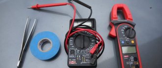
To check its functionality, just connect one end to a multimeter - a measuring sensor, and heat the other end using a gas burner or lighter.
A combined electrical measuring instrument, which can be digital and analog, combines several functions (at least the functions of a voltmeter, ohmmeter, ammeter). Multimeter
The working thermocouple should have a voltage around 50 mV.
If a thermocouple malfunction is confirmed, you can replace it yourself.
Using a microcontroller
Using a microcontroller in a homemade thermometer circuit involves using a program that controls its operation. ATmega8 is used as a microcircuit, and DS18B20 is used as a temperature sensor.
The circuit uses a small number of radio components. It is simple and does not require any adjustment after assembly. The microcontroller supply voltage is five volts. To stabilize it, the L7805 chip is used. Transistors can be used with any NPN structure. A three-digit segment display with a common cathode is suitable as an indicator.
The temperature of the device can vary from -55° to 125º C in increments of 0.1º C. The measurement error does not exceed 0.5º C. Data exchange between the sensor and the microcontroller occurs via a 1-Wire bus. If the DS18B20 measuring chip from ATmega8 is located at a large distance, it is necessary to select a pull-up resistance. It is better to solder it directly to the sensor output.
When programming, all microcontroller settings are left at factory settings and the fuses are not changed. Then you can add another sensor to the assembled thermometer, as well as a clock. But for this you will need to have programming knowledge in order to write the program code.
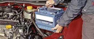
How to remove a thermocouple from a gas water heater
In order to be able to quickly repair a geyser with my own hands and always have warm water, taking into account the experience of long-term operation of gas water heaters of different models, I always have a set of spare parts on hand. Rubber gaskets, tubes, thermal relay and thermocouple included. Therefore, within half an hour the thermocouple was replaced with a new one, and the column again began to properly heat the water.
The thermocouple is secured to the left on the common bar with the igniter and spark plugs using a nut. Before unscrewing the nut, you need to slightly unscrew the left self-tapping screw holding the bar so that it does not interfere with the wrench turning.
Next, use an open-end wrench to unscrew the nut by rotating counterclockwise until it completely comes off the thread on the thermocouple body. After this, the thermocouple will easily come down from the bar.
In the next step, you need to use an open-end wrench to unscrew the contact screw from the gas-water regulating unit. The screw is located on the opposite side of the gas control knob.
All that remains is to remove two terminals from the thermal protection relay, and the thermocouple, complete with wires, will be removed from the gas water heater.
Installation of a new thermocouple is carried out in the reverse order, and it is desirable that the current-carrying wires do not touch either the internal metal parts of the gas column or the casing after its installation.
How to weld a burnt thermocouple of a geyser
Due to professional needs, I periodically have to manufacture thermocouples for devices for maintaining a given temperature in drying cabinets and in equipment for annealing twisted magnetic cores for transformers at a temperature of 800°C. Therefore, when manufacturing the next thermocouple, I decided to try to restore the functionality of a burnt thermocouple from a gas water heater by welding.
The central wire of the thermocouple was welded to the copper wire of the electrical wiring and had a length of about 5 cm. In the photograph, the soldering site is clearly visible on the left. This length of wire would be enough for several repairs.
The tubular conductor of the thermocouple, about a centimeter long, was completely burnt out, but a part of it with a thicker wall remained.
The previous welding site was removed from the central conductor, and the thermocouple parts were cleaned of soot and deposits using fine sandpaper.
The central conductor was inserted into the base of the thermocouple so that its end protruded one millimeter. Welding was carried out on a special installation, the device and circuit of which I will describe below, for about four seconds at a voltage of 80 V and a current of about 5 A.
We recommend: Infrared heated floor under linoleum: installation, instructions, video reviews
I did not make a video recording of the thermocouple welding process for fear of damaging the camera from a bright arc, but I took a photo of hot graphite powder a couple of seconds after the welding was completed.
The thermocouple junction turned out, contrary to my expectations, of excellent quality and beautiful shape. I became confident that I had not started repairing the thermocouple in vain.
To prevent the central conductor of the thermocouple from shorting to its body, fiberglass wool was tightly packed into the gap. Asbestos is also good for these purposes.
To ensure that the thermocouple was working, it was heated with a soldering iron to a temperature of about 140°C.
The multimeter recorded the EMF generated by the thermocouple as 5.95 mV, which confirmed the serviceability of the thermocouple. It remains to check the functionality of the thermocouple in the gas column.
Although the thermocouple became a centimeter shorter, its length was still quite enough for the junction to be in the igniter flame. The restored thermocouple has been working flawlessly in the gas water heater for several months now, and, I believe, will work much longer than a factory-made thermocouple, since the junction point has become much more massive.
Installation device for thermocouple welding
Attention! When repeating and operating the proposed installation for welding thermocouples, due to the lack of galvanic isolation of contacts for connecting a thermocouple, it is necessary to observe the polarity of connecting the installation to the electrical wiring. Only the neutral wire must be connected to the thermocouple. Touching a phase wire may result in electric shock.
There are several ways to weld thermocouples: in an electric arc, in a salt electric welding machine, using an acetylene torch and in graphite or carbon powder. I weld thermocouples to measure temperature using LATR and a ceramic container filled with graphite powder. The technology is simple, does not require special equipment or experience and is accessible to any home craftsman.
I inherited a homemade installation for welding thermocouples, shown in the photo. The installation is a metal box in which an LATR, an alternating voltage voltmeter and a ceramic glass for graphite powder are installed.
The electrical diagram of the installation is presented above. The supply voltage is supplied through an electrical plug from household electrical wiring through a switch and fuse for a current of 5 A to the primary winding of a laboratory autotransformer. The neon lamp HL1 serves to indicate the switched on state of the installation. Resistor R1 limits the current through HL1.
At the bottom of the ceramic bowl filled with graphite powder, there is a copper plate to supply current, to which supply voltage is supplied through a brass screw from the alternating contact of the LATR. The neutral wire coming from the power plug is connected to the common wire of the LATR and to the thermocouple being welded using an alligator clip.
The amount of welding current depends on the voltage. For this purpose, the installation has an alternating voltage voltmeter, indicated in the diagram by the letter V. The voltage value is set by rotating the LATR knob and is selected experimentally depending on the diameter of the wires being welded and lies in the range of 20-90 V. There are no special elements in the circuit that limit the amount of current. It is limited by the cross-section of the circuit wires and the resistance value of the graphite powder.
The photo shows the front panel of the thermocouple welding installation from the back side. As you can see, the LATR is fixed directly to the bottom of the box, and all other elements of the electrical circuit are fixed directly to the panel.
To weld a thermocouple on the installation, it is enough to twist the conductors, clamp them with a crocodile and smoothly touch the graphite surface. An electric arc will occur, releasing a large amount of thermal energy at one point. The conductors begin to melt, and the molten metals, mixed with each other, form a neat ball, as in the photograph, due to the forces of surface tension in the liquids.
Welding time usually does not exceed three seconds. The burning of the arc is accompanied by a characteristic hissing sound, with a decreasing frequency over time. If you have experience, you can easily determine the end of the welding process by sound. Due to the large mass of the thermocouple for the gas water heater, it took about five seconds to weld it.
Here is a photo of a chromel-alumel thermocouple made of ∅0.5 mm wires, the welding of which is demonstrated in the video above. As you can see, a neat round junction has formed at the place where the wires were welded. This thermocouple will last a long time.
On a thermocouple welding machine, I mainly have to weld chromel-copel (TCA, Type L) and chromel-alumel (TCA, Type K) thermocouples with a conductor diameter of 0.2-0.5 mm. It happened during repairs that even a K-type thermocouple with a conductor diameter of 3 mm was welded. Copper and aluminum wires with a diameter of up to 2.5 mm are well welded together. But when installing electrical wiring, it is difficult to use the installation for welding connections due to its overall dimensions.
To protect the eyes from bright light when visually monitoring the welding process, it is inconvenient to use glasses or a welder’s protective mask, so I use a high-density neutral density filter from the camera.
As practice has shown, with the help of a simple installation, which is an LATR and a ceramic bowl with graphite powder, you can successfully repair thermocouples used in gas water heater automation systems at home with your own hands.
Types of thermostats
Programmable thermostat W1209
Depending on the design and principle of operation, these devices come in three varieties: electronic, electromechanical and mechanical.
Electronic
The simplest electronic thermostat is a device consisting of the following parts:
- The controller is a printed circuit board with a microcircuit. This is the key part of the thermostat, receiving information from an external temperature sensor, processing it and sending the corresponding signal to turn on or off the heating device or air conditioner;
- Monochrome liquid crystal display and control buttons - used to configure and program the thermostat to maintain the required temperature background in the room;
- Remote temperature sensor connected to the controller using a flexible thin cable;
- Contact group - clamps in which the cores of the cable connecting the thermostat to the heating device or air conditioner are fixed.
This device works quite simply: an analog signal is sent from the sensor via a cable to the controller, which is deciphered by its microcircuit, correlated with the temperature value specified in the settings, after which the controller makes a decision to turn the heating equipment on or off.
Electromechanical
Occupying an intermediate position between electronic and mechanical, such thermostats come in two types:
- With a bimetallic plate and a contact group - inside such regulators there is a plate that, when heated to a certain level, bends, opening the contacts of the circuit that powers the heating equipment. When cooling, the reverse process occurs: the plate straightens, closes the contacts, and the heater turns on. The activation of this device is adjusted using a rotating dial with a pusher that changes the distance between the plate and the stationary contacts it closes.
- With a capillary tube - the design of such a device is the same as analogues used in water heaters and boilers.
Electromechanical room temperature controller
Checking the thermocouple of a home geyser
Long-term operation of a home geyser fully allows for such a moment when the thermocouple fails. In this case, it is necessary to check the functioning of the system and, accordingly, check the control sensor itself.
Of course, not all owners of gas equipment are able to perform such work. And from a safety point of view, the best solution would be to contact the gas company to solve this problem.
But at the same time, situations may be different, including the impossibility of contacting specialists for some reason. Then the only option left is to try to do the work yourself.
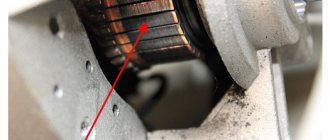
The picture shows one of the options for an installed thermocouple that needs to be checked: 1 – the directly hot area of the sensor, which is most often susceptible to destruction; 2 – fastening nut, which must be unscrewed for dismantling; The same nut can be used on the other end of the thermocouple
In this scenario, a user inexperienced in gas matters is interested in how to check the thermocouple on a gas boiler using a tester - a common electrical and electronics diagnostic device. Let's try to reveal this technological point in order to make the task easier.
We recommend: Kiturami gas boiler: design, technical specifications, operating instructions and owner reviews
Stage #1 - preparation for testing by a tester
To begin with, let us remind you that a tester is a measuring device - pointer or digital, with which it is possible to measure:
- resistance;
- voltage value (AC and DC);
- current strength (AC, DC).
The measured values marked are sort of basic. Moreover, modern testers are able to check a number of other parameters, for example, inductance or capacitance.
But taking into account the principle of operation of the thermocouple of a household gas boiler, the voltage measurement mode in the millivolt range is quite sufficient.
The procedure for testing a thermocouple using a measuring device and a simple heating element - a paraffin candle. As can be seen from the tester readings (25 mV), the gas burner flame control sensor is working properly
In addition to the measuring instrument (tester), the installer will need another fairly simple tool - a heating source. It is better if such a source has the ability to emit an open flame. Therefore, the best option here would be to use a regular paraffin candle.
Stage #2 - visual inspection for defects
The procedure for testing the flame control sensor is simple. However, before proceeding with the hot test, it is recommended to carefully examine the thermocouple visually from the outside.
When inspecting the area of the junction and the descending rod, physical defects of the metal, including burnout areas, should not be visible on the surface.
Stage #3 - testing the sensor's performance
After completing the visual inspection, you can proceed directly to the hot test. To do this, the junction area and the downward section of the gas column thermocouple rod are placed above the candle wick.
Next, a measuring device (tester) is connected to the terminal ends of the thermocouple, after which the candle is lit. The generated potential is observed on the working scale of the measuring device.
In fact, to check the functionality of the sensor, it is permissible to use any suitable heating source, for example, a household lighter. True, depending on the power of the heating source, the readings on the tester may be below normal or, conversely, above normal
The absence of any electrical potential readings clearly indicates a sensor malfunction. In case of partial defects, chaotic (unstable) readings of units of millivolts may be observed on the measuring device. If the geyser sensor is working properly, a stable value equal to tens of millivolts (20-30 mV) is usually recorded on the device.
Moreover, as the thermocouple body is heated by a candle flame, the readings on the instrument scale change slightly upward. If the candle flame is extinguished, the tester readings will tend to zero as the rod body and junction area cools. That's all. With this development of events, the thermocouple, as being in good working order, can be safely placed at the site of action.
Accurate thermometer
The use of semiconductor diodes and transistors as sensors is characterized by the difficulty of calibrating readings, which ultimately leads to an error in the measurement result. Therefore, to obtain an accurate result, a bifilar wound coil of thin conductor, placed in a cylinder with dimensions of about 4 × 20 mm, is used as a meter.
The basis of the design is the ICL707 chip and a glowing indicator. Power can be supplied from any source with an output amplitude of 12 V. The DA3 contains a normalizing converter that changes its output voltage depending on the signal received from the sensor.
The setting consists of setting the voltage on the 36th leg of the microcircuit to one volt. This is done using resistors R3 and R4. Instead of the sensor, a 100 Ohm resistor is connected. By changing resistance R14, zeros are set on the digital indicator. After which the device is ready for measurements.
Possible malfunctions and methods for eliminating them
If, when you press the gas supply button, the burner turns on and immediately goes out, this indicates a malfunction of the thermocouple. It may also be the result of poor contact between the converter and the solenoid valve.
Repairing a gas boiler thermocouple malfunction is as follows:
- remove the end of the thermocouple by unscrewing the clamping nut with a wrench, with which the transducer is attached to the valve;
- if upon inspection the presence of contaminants or oxides is detected, clean the contact area with fine sandpaper;
- Next, use a multimeter to check the functionality of the device.
If, when checking, the sensor shows a voltage of 50 mV, you can try to start the boiler. If the problem persists and the burner goes out, this may indicate a faulty solenoid valve.
If the valve is in working condition, it is necessary to ensure the correct connection of the converter to the valve: find the appropriate position of the clamping nut for optimal contact.
You should know that if the gas boiler converter fails, the device cannot be restored. Here it is necessary to replace the thermocouple by installing a new sample in its place. Products in this category are offered by many domestic and foreign manufacturers, including Arbat, Zhukovsky AOGV plant, Honeywell concern and other industrial companies. The price range for this device varies between 600-2000 rubles.
The main areas of application of thermocouples are automation of gas equipment, foundry industry installations and many other areas of production. Based on this device, a whole range of thermostats and thermometers for household and industrial use has been developed. In the hands of folk craftsmen, a thermoelectric converter can become the basis for a mini power station; it is used to create chargers with which you can charge low-power devices from an open fire, including from a fire.
Concept of temperature controllers
Products in this category are used to solve various problems. Based on the appropriate temperature threshold setting, power is supplied (turned off):
- heating in the cellar;
- heating the soldering station;
- boiler circulation pump.
From the examples given, the basic requirements for accuracy that a suitable thermostat circuit must provide are clear. In some situations it is necessary to maintain a given level no lower than ±1C°. To monitor operating parameters, an operational indication is needed. Load capacity is essential.
The listed features explain the purpose of typical functional units:
- the temperature value is recorded with a specialized sensor (resistor, thermocouple);
- the readings are analyzed by a microcontroller or other device;
- the actuator signal is sent to an electronic (mechanical) switch.
For your information. In addition to the parts discussed, the thermal relay circuit may contain additional components to supply power to an electric heater or other powerful load.
How and in what cases can it be restored?
The thermocouple is designed in such a way that any damage or contamination can reduce the voltage it produces below a critical level. A very common cause of malfunction is carbon deposits or a layer of soot on its working (heated) part. To restore the thermocouple, just clean it with a soft brush or cotton wool and alcohol, while avoiding scratches and other damage. After cleaning, it is worth checking the voltage again following the instructions above.
Oxidized contacts are also a common cause; they can be carefully treated with sandpaper. If the thermocouple has a deep black dent or hole due to burning, it is guaranteed to need to be replaced.
Main causes of failure
Malfunctions and their causes:
- A burning smell appears when plugged in. In this case, you must first check the slab visually. To do this, turn it off from the power supply and inspect the burners. If the reason is accumulated and burnt food residues, remove them and rinse the surface well.
If the stoves are clean, but a burning smell still emanates from the equipment, then the problem may be a faulty wiring. You need to call a technician or try to repair it yourself.
- The heating element stops heating. The cause was the connecting wires or the burner. First, check the control parts, which often lose contact. If this does not help, you need to completely replace the heating element with a working one.
- Due to a broken switch, it is not possible to set the required heating temperature for the burner. The reason is the displacement of contacts, their disconnection.
- Problems with the coil are detected when the burner heats up poorly or is absent. The spiral may be damaged due to overheating, rupture, or moisture ingress.
- The oven may heat unevenly or may not reach the desired temperature. In this case, it's a matter of heating elements. Repair or replacement is necessary.
Important You can repair glass-ceramic stoves yourself if you carefully study the operating instructions and know the structure of the electric stove. Otherwise, you need to call a specialist at home