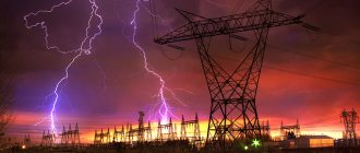
A thunderstorm, as a natural phenomenon, is accompanied by lightning that strikes mainly tall objects. The high energy inherent in lightning discharges, under unfortunate circumstances, can lead to:
- destruction of elements of an architectural object;
- failure of electronic equipment;
- the occurrence of a fire;
- death of people and farm animals.
The only way to prevent this is a lightning protection device. The purpose of lightning protection is to forcefully drain the atmospheric discharge current directly to the ground along a ground loop specially created for this purpose, which avoids its direct impact on building structures, animals and people. Lightning protection of a building is performed as a separate engineering system. The serviceability of the lightning protection system is confirmed by regular checks.
Who conducts the inspection?
Issuing a conclusion on the compliance of the lightning protection system of industrial buildings with the requirements of the standards is a technically complex procedure that can only be performed by specialized organizations.
The necessary conditions for issuing a lightning protection inspection protocol include the following provisions:
- the inspection organization has a testing laboratory, which is additionally confirmed by a registration certificate;
- specialized education of laboratory staff;
- application when testing measuring instruments with valid verification.
A laboratory is an independent structural unit of an organization with an approved staffing table.
Installation companies usually subcontract a certification laboratory.
Electrical laboratory services
Despite the relatively low probability of being used for its “direct” purpose at most facilities, the lightning protection system is included in the list of special responsibility, since not only the integrity of expensive equipment or building structures, but also human lives, as a rule, depend on its performance.
Therefore, it is better to entrust the creation and maintenance of such systems to professionals - a licensed electrical laboratory with qualified personnel using certified electrical measuring instruments. One of these professional organizations is the electrical engineering laboratory (ETL) "Mega.ru", which provides a wide range of services to organizations and individuals in Moscow, the Moscow region, as well as surrounding areas.
You can order work, get advice or clarify details of cooperation by calling the phone numbers and e-mails published on the “Contacts” page, or simply using the feedback form in the side column of the site.
Types of checks
Inspections of lightning protection elements, regardless of their execution, are divided into control, extraordinary, and one-time.
- The main distinguishing features of lightning protection control checks are their implementation in a full cycle with measurement of characteristics and according to a pre-agreed plan.
- Extraordinary inspections are usually carried out by visual inspection after natural disasters, as well as particularly severe thunderstorms. Resistance measurements are not performed.
- One-time lightning protection checks of various depths are performed after:
- completion of system installation;
- making any changes to the system, incl. repair;
- damage to the protected object.
What is the regularity of diagnostics of lightning protection systems?
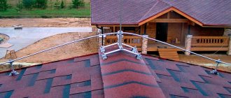
Laying circuit of the lightning removal device
We invite you to watch a video that will help you determine the correct tactics for installing lightning protection at home.
The frequency of revisions in relation to the lightning protection device primarily depends on the requirements established in the technical regulations. They also often rely on the classification of structures on which lightning rods are provided; depending on this, a certain number of checks are carried out. So, if a building is assigned category 3, therefore, according to the documents, control is carried out once a year.
The highest categories, which are installed on structures equipped with a lightning protection system, allow research work every three years. Leading electricians recommend combining the testing schedule with optimal weather conditions, that is, at the time of maximum frost or high aridity of the soil in a given region.
Lightning protection testing should be carried out with special devices. A megohmmeter is considered a good assistant in ensuring the reliability of the data obtained. Exceptional calculations can only be obtained by making sure that the device has a certificate and is registered with the state.
Test procedure
The lightning protection system of architectural structures, especially industrial facilities, is often highly complex. This requires dividing the process of monitoring its current state into a number of stages, which are performed using a variety of visual and instrumental testing methods.
Stages
Typically, in the process of certification of a lightning protection system, the following stages are distinguished:
- obtaining the necessary initial data from existing design documentation;
- monitoring the actual compliance of the system with project documentation;
- visual inspection of system devices. The purpose of the inspection is to control the integrity of welded joints (with tapping), the absence of corrosion, and the condition of contacts;
- measurement of grounding resistance.
In situations where several lightning rods are used to protect an object, the test is carried out separately for each of them.
Normalized parameters
Lightning protection of industrial facilities (architectural structures plus communications) is checked for compliance with the requirements of departmental instructions RD 34.21.122-87 and SO 153-34.21.122-2003 of the Ministry of Energy. The provisions of PTEEP (Chapter 2.8) standardize the principles of protecting electrical devices from the effects of voltage surges.
The standards fix the maximum transition resistance of lightning protection contacts at 0.03 Ohm. The maximum resistance of the grounding device is set to 10 ohms.
When installing electrical installations, they additionally monitor compliance with regulatory requirements for the distance to the object, the size of the recess, as well as the design of the elements of the grounding device in places with different soil resistance. Separately, check the minimum distance of the grounding conductor from metal communications.
Measurement methods
During instrumental monitoring of lightning protection, the following types of resistance measurements are performed:
- checking the contact resistance of circuits at the junction of individual components;
- determination of the resistance of protection grounding conductors.
The reliability of the results is increased by testing grounding devices at the peak of the dry season or at the deepest freezing of the soil.
During visual inspection of lightning protection, which is carried out during the day in clear weather, the degree of corrosion and other damage to the surface and structure of system components is checked. If, for example, during an inspection of lightning rods, those with more than a quarter of the surface area damaged are found, they must be replaced.
Documentation (acts, protocols)
Based on the results of checking any specific parameter or their complex, a protocol is drawn up. In relation to the lightning protection system, the following protocols are distinguished:
- visual inspection of the technical condition of the system and/or its individual components;
- contact resistance measurements;
- resistance measurements when testing the contour of grounding devices.
The protocol can be drawn up in relation to part of the system, and also contain the results of a full cycle of examinations without breaking it down into separate components. In measurement protocols, which are drawn up in accordance with GOST R 50571.16-99 (harmonized with IEC 60364-6-61-86):
- note the measurement conditions;
- give a description of the object;
- describe the type of testing equipment;
- record identified violations;
- note the data of the persons who performed the tests.
The document must contain all the information necessary to substantiate the conclusion based on the test results in the “pass-fail” form in relation to normal technical operation.
The protocols are supplemented with a lightning protection organization diagram, copies of verification certificates, certificates of certification of laboratory employees and other necessary documents. A sample protocol form is shown in Figure 1.
Figure 1. Approximate form of a protocol for measuring parameters of a lightning protection system
The act differs from the protocol in that it is always drawn up collectively. The Commission, according to established tradition, includes an odd number (at least three) members. The act is additionally approved by the customer’s manager or one of his deputies.
In relation to lightning protection, an inspection report and an acceptance certificate are drawn up.
Acts of inspection are de facto carried out in the form of a protocol.
Acceptance reports include measurement protocols. Often such an act is a general document, the content of which is completely included in the appendices.
Documentation of tests
The main working document, which is considered confirmation of the truth of the results obtained, is a test report, in separate sections of which all data about the lightning protection system is recorded. Meter readings taken during testing in specific climatic conditions are entered in the specially designated columns of this document.
When any device is put into operation, taking into account the results obtained during its examination and based on the control data of the operating protocol, two passports are issued for it at once. One of them applies to the entire lightning protection system as a whole, and the second - only to its memory.
The inspection protocol (erroneously called the inspection report), upon completion of all test procedures, is transferred for permanent storage to an authorized person who bears full responsibility for the entire energy sector of the facility.
Below is a sample form of a lightning protection system inspection protocol .
Protocol for testing the lightning protection system. Sheet 1
Protocol for testing the lightning protection system. Sheet 2
In the final part of the review, we note that a set of measures for the general verification of the reliability of lightning protection is organized in order to assess the serviceability of this equipment. The test results obtained make it possible to ensure that it is suitable for use until the next scheduled inspection.
Necessary measuring equipment and instruments
The quality of the lightning rod installation is checked using appropriate measuring equipment. Both automated and manual meters are available. Manual equipment is considered obsolete and is gradually being phased out.
The most widely used among automated lightning protection testing devices is the Polish-made MRU-101. Meter MRU-101:
- Performs ground resistance measurements;
- determines the resistivity of the geosubstrate;
- measures the spreading current;
- selects a range with the necessary settings after pressing the START key;
- stores several hundred test results.
The strength of the MRU-101, the interface of which is shown in Figure 2, is constant monitoring of the noise level and measurement conditions with a complete stop of the process when gross errors are detected. In addition, when the device determines that unreliable readings may be obtained, it generates a warning message.
Figure 2. Controls, probe connectors and indicator of the MRU-101 meter
To carry out lightning protection tests, a three-pole circuit is most often used, the structure of which is shown in Figure 3 with the working inputs H, S, E of the meter being connected to three different measuring probes driven into the ground in the area of the grounding loop electrodes. The distance between the probes is chosen to be at least 20 m.
Figure 3. Three- and four-pole diagrams for connecting the MRU-101 device to measuring probes
A four-pole circuit is less commonly used. Its difference from the three-pole one is the connection of the ES input with an additional wire to the same electrode that is connected to the E input (see Figure 3).
MRU-101 also allows you to measure the spreading current using a non-contact method. To do this, connect the measuring clamps, which are included in the delivery kit, to the fifth input as shown in Figure 4. Measurements require preliminary calibration of the clamps, performed automatically.
Figure 4. Connection diagram of measuring clamps to the MRU-101 device
Types of lightning protection systems
External lightning protection systems
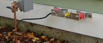
They are exposed to primary atmospheric electricity. Their task is to receive a thunderstorm charge, direct it along a safe path and ensure its spread in the ground. External systems are made up of lightning rods, current conductors (lightning rods, descents) and a grounding device (GD).
In lightning protection projects, the lightning rod function is mainly assigned to rod, cable or mesh elements.
To capture the atmospheric charge, large metal structures can also be used - searchlight masts or roofs of buildings made of corrugated sheets. The last option is typical for lightning protection devices in private homes.
The designs of external MSMs are characterized by both relative simplicity and high efficiency. Therefore, the majority of checks on the condition of such lightning protection come down to a careful inspection by a qualified specialist or measurement of the resistance of its circuit.
For example, when examining an air terminal in the form of a metal roof, special attention is paid to
- number of grounding points - there must be at least two of them, connected into a single closed loop;
- arrangement of current drains, which must be connected to the roofing deck along its perimeter every 20 m.
Internal lightning protection systems
Prevents sparking in an electrical installation, and also helps to dampen short-term high-voltage network pulses (running waves) caused by the electromagnetic effects of lightning discharges. Smoothing of dangerous impulses is achieved by using shielding systems, potential equalization, surge protection devices (SPDs), including arresters and nonlinear surge suppressors.
The performance of devices used in internal interconnection systems cannot always be determined visually.
Therefore, to test lightning protection devices, ENERGO-TEAM engineers use special testers and pulse current generators, for example EUROTEST and TESTER H1.
Let's sum it up
Installation of a lightning protection system in a private house
After taking measures to check the performance and resistance of the lightning protection device, workers must provide the owner of the structure with documentation with calculated and double-checked data.
In addition to tables with calculations, it is customary to include in the report the proposed methodology and all stages of work, during which the resistance values of the lightning rod installation were obtained. Based on the results, the performance of the device is monitored and a serviceability category is assigned to it. Otherwise, repair work or a complete replacement of lightning protection conductors and grounding is prescribed, if necessary.
Tags: ampere, beat, sconce, type, choice, generator, house, , grounding, sign, measurement, test, cable, how, category, design, circuit, , tray, magnet, lightning protection, monitor, installation, voltage, frequency , potential, rule, check, wire, project, start-up, , work, calculation, revise, repair, row, system, resistance, term, circuit, ten, type, current, current, , shield, effect
Three-pole measuring system
For measuring the resistance of a lightning protection system, the method is considered basic. The work is carried out as follows:
- The ground electrode is connected to the measuring socket of the equipment.
- The current probe is directed into the ground. The measurement is carried out at a distance of over 40 meters from the protective system. The probe is connected with a special conductor to the socket of the device called “H”.
- The potential probe is installed in the ground at a distance of more than 20 meters from the protective system being studied. Next, the probe is connected to the measuring socket marked with the letter S.
- The probes and the ground electrode are lined up in a single line.
The rotary switch is placed in position RE 3p. Next, measurements begin after pressing the START key.
After the procedure is completed, the ground resistance indicator (RE) and the data obtained from the probes appear on the monitor. The distance between the potential probe and the protective system is reduced to one meter. Then they take another measurement. If the results differ by more than 3%, the current probe is moved further away. The measurement is carried out repeatedly until an acceptable ratio of the obtained data is obtained.
Measurements using a three-pole circuit involve taking into account several nuances. For example, with increased resistance of the probes, this indicator for grounding is set with a certain error. The same should be said about measurements of the resistance of the ground loop, which is in free contact with the ground. The reason for the existing errors is the excessively high ratio of the resistance of the probes and the ground electrode.
To improve the accuracy of the data obtained, it is necessary to achieve better contact of the probes with the ground. For this purpose, the probes are moved to another, more humid place. An alternative to this solution is to artificially moisten the soil before performing the test. In addition, you need to inspect the measuring conductors to ensure the integrity of the insulating material, the absence of traces of rust, and check the contacts with the probe terminals.
Note! The results of all additional procedures are recorded in the final protocol. Compliance with all recommended conditions allows you to obtain fairly accurate results (taking into account the general measurement error)
It should be borne in mind that a correct assessment of the influence of the resistance of the probes requires additional calculations
Compliance with all recommended conditions allows you to obtain fairly accurate results (taking into account the general measurement error). It should be borne in mind that a correct assessment of the influence of the resistance of the probes requires additional calculations.
Technical events
The list of necessary technical measures is determined by the person who allows the work together with the manufacturer in accordance with the requirements of SNiP 12-03-99.
When inspecting and checking the condition of lightning rods and down conductors on the roofs of buildings and structures, it is necessary to use installer safety belts. If the length of the belt sling is insufficient, it is necessary to use a safety rope previously secured to the building structure. In this case, one of the persons conducting the tests slowly lowers or tightens the safety rope. When checking welded joints of external current conductors and the design of lightning rods, the tool (hammer) must be tied to avoid falling. When a thunderstorm approaches, all work must be stopped and the team removed from the workplace.
Standardized values
Protection against direct lightning strikes of buildings and structures classified as Category I according to lightning protection devices must be carried out using free-standing rod or cable lightning rods
Protection against direct lightning strikes of buildings and structures classified as lightning protection categories II and III, with a non-metallic roof, must be carried out by separate rod or cable lightning rods or installed on the protected object.
When the roof slope is no more than 1:8, a lightning rod can be used as a lightning rod, made of steel wire with a diameter of at least 6 mm with a cell pitch for protection category II of no more than 6x6 m and 12x12 m for II I laid to grounding conductors no less than through 25 m along the perimeter of the building, they should be located no closer than 3 m from the entrances to buildings and in places inaccessible to the touch of people and animals. protection categories. Down conductors from a metal roof or lightning protection mesh must be
In all of the above cases, reinforced concrete building foundations should additionally be used as natural grounding conductors for lightning protection systems.
The dimensions of lightning rods, down conductors and grounding elements are given in Table 1.
TABLE 1.
| Shape of lightning rods, down conductors | Outside | In the ground |
| Rod lightning rods (steel) - cross-section no less - length not less | 100 mm2 200 mm | — — |
| Cable lightning rods (multi-wire steel rope) - cross-section no less - length | 35 mm2 depending on the protection zone | — — |
| Round down conductors and jumpers (steel) - diameter not less | 6 mm | — |
| Round vertical electrodes (steel) - diameter not less | — | 10 mm |
| Round horizontal electrodes (steel) *—diameter no less | — | 10 mm |
| Rectangular down conductors and grounding conductors (steel) - cross-section no less - thickness not less | 48 mm2 4 mm | 160 mm2 4 mm |
*Only for equalizing potentials inside buildings and for laying external contours at the bottom of the pit along the perimeter of the building. Connections of lightning rods with down conductors and down conductors with grounding conductors must be made by welding, and if hot work is not allowed, by bolted connections with a transition resistance of no more than 0.05 Ohm. Welds should not have cracks, burns, lack of penetration of more than 10% of the length of the seam, unfilled craters and undercuts. The surface of the seam should be uniformly scaly, without sagging. The length of the weld must be: for a design of round sections at least 6d (d is the diameter of the lightning rod, down conductor, grounding conductor), rectangular - 2 V, where B is the width of the steel strip of lightning protection system structures (clause 3.2 of VSN 164-82, GOST 10434-82, SNiP Sh-33-76 section II).
This is interesting: High voltage in the network - what to do and where to complain
Gallery of completed objects
Engineering LLC. Address: Nizhny Novgorod region, Kstovo, Lukoil-Energoseti.
Work on diagnostics of cable lines and electrical equipment using the partial discharge method. High-voltage testing and fault location of cable lines with cross-linked polyethylene insulation. End 2014
"SPbVS" Branch of JSC "Lenenergo"
CJSC "First Container Terminal" Address: St. Petersburg, Mezhevoy Canal, 5.
CJSC "PNT" St. Petersburg, Elevator platform, 32.
GazpromInvestZapad LLC. Portovaya compressor station as part of the construction of the North European Gas Pipeline. Section Gryazovets-Vyborg.” On-site power supply networks, instrumentation and automation, communications, fire alarm systems, a set of technical security equipment. End 2012.
Engineering LLC. Address: Nizhny Novgorod region, Kstovo, Lukoil-Energoseti.
Department of the Federal Service for State Registration, Cadastre and Cartography for St. Petersburg.
VVK Stroy-Corporation LLC.
OJSC "Kubanenergo"
Forum LLC. Address: St. Petersburg, intersection of Shuvalovsky Prospekt and Parachute Street.
Secretary of the Council of the Interparliamentary Assembly of Member States of the Commonwealth of Independent States. Address: St. Petersburg, st. Shpalernaya, 47.
SEC LLC
JSC Lenenergo
- Determination of locations of damage to cable lines in areas of the Cable Network. End 2013
- Diagnostics by partial discharge method of cable lines with cross-linked polyethylene insulation and impregnated paper insulation. End 2013
JSC FGC UES
- Reconstruction with replacement of equipment at the 220 kV Primorskaya substation. End 2013
- Reconstruction with replacement of equipment at the 110 kV Elton substation. End 2013
- Execution of design and survey work, RD and supply of equipment and construction, installation and commissioning work on the 330 kV overhead line KNPP-Yuzhnaya 2. Completion of 2013.
Baltnefteprovod LLC.
- Technical diagnostics and high-voltage testing of 110 kV cable lines using the partial discharge method using the OWTS 250 installation. End of 2013.
- Maintenance of power equipment, electrical measurements up to 1000 V. End of 2014.
- Clearing of trees and shrubs and expansion of clearings of 10 kV overhead lines. End 2014
JSC "BBT" St. Petersburg, Coal Harbor, Elevator site, 28.
Construction, installation, electrical installation and commissioning work on organizing power supply. Completion date 2013
Requirements SO 153-34.21.122-2003
In addition to issues related to the arrangement of lightning protection at government facilities of any form of ownership, the instructions under this designation discuss the procedure for preparing and storing all accompanying documents.
Documentation
The as-built documentation prepared in this case must include a complete set of calculations, diagrams, drawings and explanatory notes that determine the procedure for installing special equipment within the protected area.
When preparing it, both the location of the building on the general development plan (taking into account the laid communications) and the climatic conditions in the area should be taken into account.
Delivery of the object
In addition, this document establishes the general procedure for the technical acceptance of lightning protection systems, as well as the specifics of their commissioning. It is specifically stipulated that for the acceptance of a building or structure, a special commission is appointed, consisting of representatives of the contractor and the customer, as well as a fire service inspector.
Based on the results of studying the documentation provided by the developer, acts of acceptance and admission of lightning protection equipment into operation are issued.
After this, special working passports must be issued for each individual device (for the entire system and the ground electrode), which remain with the person responsible for the electrical facilities of the facility.
Examination
In the sections of the instructions relating to the operation of the lightning protection devices put into operation, it is separately stipulated that the procedure for their maintenance and maintenance is determined by the basic provisions of the PUE. At the same time, in order to maintain the systems in working order, annual inspections of all its components must be carried out.
Such surveys are organized before the start of the thunderstorm season, as well as after any changes or improvements are made to the lightning protection design.