Design
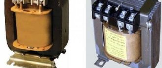
The first bipolar transformer was made by Faraday, and according to the data, it was a toroidal device. A toroidal autotransformer (brand Shtil, TM2, TTS4) is a device designed to convert alternating current from one voltage to another. They are used in various linear installations. This electromagnetic device can be single-phase or three-phase. Structurally consists of:
Photo - the principle of operation of the transformer
A device of this type is used in various audio and video installations, stabilizers, and lighting systems. The main difference between this design and other devices is the number of windings and the shape of the core. Physicists believe that the ring shape is the ideal design for an anchor. In this case, the winding of the toroidal converter is carried out evenly, as well as the heat distribution. Thanks to this arrangement of the coils, the converter cools quickly and even during intensive operation does not require the use of coolers.
Photo – finished TPN25
Video: purpose of toroidal transformers
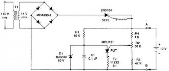
Rectifier block
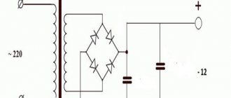
By itself, a 220 to 12 Volt transformer will not produce direct current; you need to use additional devices. This is a rectifier, filter and stabilizer. The first is performed on one or more diodes. The most popular scheme is the bridge. It has many advantages, the main ones being minimal voltage losses and high quality output current. But it is also possible to use other rectifier circuits.
A conventional electrolytic capacitor is used as filters, which allows you to get rid of the remnants of the alternating component of the output current. A zener diode installed at the output allows you to keep the voltage at the same level. In this case, even if there is ripple in the 220 V network and in the secondary winding at the rectifier output, the voltage will always have the same value. This has a good effect on the operation of devices that connect to it.
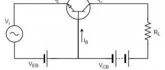
Principle of operation
The simplest toroidal transformer consists of two windings on a ring and a steel core. The primary winding is connected to a source of electric current, and the secondary winding is connected to a consumer of electricity. Due to the magnetic circuit, the individual windings are connected to each other and their inductive coupling is strengthened. When the power is turned on, an alternating magnetic flux is created in the primary winding. Meshing with individual windings, this flux creates an electromagnetic force in them, which depends on the number of turns of the winding. If you change the number of windings, you can make a transformer to convert any voltage.
Photo - Operating principle
Also, converters of this type are either buck or boost. A toroidal step-down transformer has a high voltage on the secondary winding terminals and a low voltage on the primary winding. Increasing is the opposite. In addition, the windings can be of higher or lower voltage, depending on the characteristics of the network.
Calculation using an example
Let's say we have the following parameters:
- The window is 53 mm high and 19 mm wide.
- The frame is made of textolite.
- Upper and lower cheeks: 50 mm, frame 17.5 mm, therefore the window measures 50 x 17.5 mm.
Next, you need to calculate the diameter of the wires. Let's say you need the power to be 170 W. In this case, the current on the network winding will be equal to 0.78 A (power divided by voltage). In the design, the current density turns out to be 2 A/sq. mm. Having this data, you can calculate that you need to use a wire with a diameter of 0.72 mm. It is also possible to use 0.5 mm, 0.35 mm, but the current will be less.
From this we can conclude that to power radio equipment using lamps, for example, you need to wind 950-1000 turns for the high-voltage winding. For incandescence - 11-15 turns (the wire just needs to be used with a larger diameter, depending on the number of lamps). But all these parameters can also be found experimentally, which will be discussed further.
How to do
Even young electricians can make a toroidal transformer. Winding and calculation are not complicated. We suggest considering how to properly wind a toroidal magnetic circuit for a semi-automatic machine:
- A special machine can be used to wind a transformer on a ferrite core. It will help significantly speed up work and reduce the likelihood of iron jumping off. It can be made as a clamp for wrapping wires;
- It should be noted that the latres that are needed for winding must be the same size. When winding, make sure that there are no gaps between the sheets. If your power transformer has small gaps in the magnetic circuit, then they can be filled with iron sheets from any other transformer, cut to a certain size;
Photo – calculation - After winding of the iron is completed, its terminals are secured by welding. This will prevent the winding from unwinding. Literally two or three weld points are enough;
- After this, the ends of the magnetic circuit are coated with epoxy glue. The edges are first slightly rounded;
- Insulation is wound over the side of the amplifier - it can even be a sheet of cardboard. It can be attached using masking tape. We repeat the action on all surfaces of the magnetic circuit;
- Now you need to wrap textile tape around the cardboard insulation. It is sold in special electrical stores. On top of this layer of insulation you can wrap an additional layer of masking tape;
- Now a wire of the selected cross-section is screwed onto the ring; a special program will help you calculate the size of the wires and the required characteristics. After finishing the winding, everything is covered with NC varnish, one terminal of the winding should remain free;
Photo - winding the winding - Then you need to make insulation from varnished fabric or textile tape, on top of which the second winding is wound. It is also varnished. All that remains is to screw on the last insulation and protect it. Continue actions until the required number of windings is obtained;
Photo - tape wrapping - The secondary winding is wound from a larger wire cross-section. If a network transformer is needed for arc welding, then it is necessary to add a certain number of turns at the end, in addition to the calculated winding ones.
Considering that 1 turn carries 0.84 Volts, the winding circuit of a toroidal transformer is carried out according to the following principle:
| Number of turns on the primary winding | Secondary voltage, V |
| 260 | 30 |
| 271 | 31 |
| 282 | 28,8 |
| 294 | 27,6 |
| 309 | 26 |
| 334 | 24,4 |
| 359 | 22,6 |
| 389 | 20,9 |
| 419 | 19,4 |
| 434 | 18,7 |
So you can easily make your own 220 to 24 volt toroidal transformer. The described circuit can be connected to both arc welding and semi-automatic welding. The parameters are calculated based on the wire cross-section, number of turns, and ring size. The characteristics of this device allow for stepwise adjustment. Among the advantages of the assembly principle: simplicity and accessibility. Among the disadvantages: heavy weight.
Arrangement of the reel housing
The body is made of high-quality cardboard paper. Its inner side is slightly larger compared to the core part of the core. When using an O-shaped core, several coils will be required. With a w-shaped core, it is enough to use only one coil.
When using a round core, it should be wrapped using insulation. Then you can carry out wire winding. Once you are done with the primary winding, it should be covered with several insulating layers. After this you need to wind the next layer. The ends of the existing windings are brought out to the outside.
When using magnetic wire, the transformer body is assembled step by step:
- A certain size of sleeve with the required cuffs is cut out.
- Cardboard cheeks are created.
- The main part of the coil is rolled up into a special box.
- Cheeks are placed on the sleeves.
Price overview
You can buy a toroidal transformer HBL-200 in any city in the Russian Federation and CIS countries. It is used for various audio equipment. Let's look at how much the converter costs.
Two compound roots “magnet” and “wire”, connected by the letter “o”, determine the purpose of this electrical device, created to reliably pass magnetic flux through a special conductor with minimal or, in some cases, certain losses.
The electrical industry widely uses the mutual dependence of electrical and magnetic energies, their transition from one state to another. Numerous transformers, chokes, contactors, relays, starters, electric motors, generators and other similar devices operate on this principle.
Their design includes a magnetic circuit that passes a magnetic flux excited by the passage of an electric current for further conversion of electrical energy. It is one of the components of the magnetic system of electrical devices.
The magnetic core of an electrical product (device) (Coil flux guide) is the magnetic system of an electrical product (device) or a combination of several of its parts in the form of a separate structural unit (GOST 18311-80).
What is the magnetic circuit made of?
Substances that are included in its design may have different magnetic properties. They are usually classified into 2 types:
To distinguish them, the term “magnetic permeability µ” is used, which determines the dependence of the created magnetic induction B (force) on the magnitude of the applied voltage H.
Read also: How many buckets in a cube of concrete
The above graph shows that ferromagnets have strongly pronounced magnetic properties, while paramagnetic and diamagnetic materials have weak ones.
However, the induction of ferromagnets with a further increase in tension begins to decrease, having one clearly defined point of maximum value, characterizing the moment of saturation of the substance. It is used in calculations and operation of magnetic circuits.
After the cessation of the tension, some part of the magnetic properties remains in the substance and, if an opposite field is applied to it, then part of its energy will be spent on overcoming this part.
Therefore, in alternating electromagnetic field circuits, the induction lags behind the applied voltage. A similar dependence of the magnetization of ferromagnetic matter is characterized by a graph called hysteresis.
On it, the points Hk show the width of the loop, which characterizes the residual magnetism (coercive force). Based on their size, ferromagnets are divided into two categories:
1. soft, with narrow loop characteristics;
2. solid, having a high coercive force.
The first category includes soft iron alloys and permoloy. Cores for transformers, electric motors and alternating current generators are made from them because they create minimal energy consumption for magnetization reversal.
Hard ferromagnets made of carbon steels and special alloys are used in various designs of permanent magnets.
When choosing a material for a magnetic core, losses on:
eddy currents created by the action of EMF induced by magnetic flux;
aftereffect due to magnetic viscosity.
For magnetic core structures operating on alternating current, special grades of thin-walled sheet or coil steel are produced with varying degrees of alloying additives, which are produced by cold or hot rolling. Moreover, cold-rolled steel is more expensive, but has lower induction losses.
Plates or strips are created from steel sheets and rolls using mechanical processing methods. They are coated with a layer of varnish to protect and provide insulation. Double-sided coating is more reliable.
For relays, starters and contactors operated in DC circuits, magnetic cores are cast in solid blocks.
AC circuits
Among them, two types of magnetic cores are common:
The first type is made of two rods, on each of which two coils with high or low voltage windings are mounted separately. If you place one HV and LV winding on the rod, then large energy dissipation flows arise and the reactance component increases.
The magnetic flux passing through the rods is closed by the upper and lower yokes.
The armored type has a rod with windings and yokes, from which the magnetic flux bifurcates into two halves. Therefore, its area is twice the cross-section of the yoke. Such designs are more often found in low-power transformers, where large thermal loads on the structure are not created.
Power transformers require a large cooling surface for the windings caused by the transformation of increased loads. A rod diagram is better suited to them.
For them, you can use three single-phase magnetic cores, spaced by one third of the circumference, or assemble windings on common iron in their own cells.
If we consider a common magnetic circuit of three identical structures, spaced apart by 120 degrees, as shown in the upper left part of the picture, then inside the central rod the total magnetic flux will be balanced and equal to zero.
However, in practice, a simplified design located in one plane is more often used, when three different windings are placed on a separate rod. With this method, the magnetic flux from the outer coils passes through the large and small rings, and from the middle one through the two adjacent ones. Due to the formation of an uneven distribution of distances, a certain imbalance of magnetic resistances is created.
It imposes separate restrictions for design calculations and some operating modes, especially idle speed. But in general, such a magnetic circuit diagram is widely used in practice.
The magnetic circuits shown in the upper pictures are made of plates, and coils are put on the assembled rods. This technology is used in automated enterprises with a large machine park.
In small industries, manual assembly technology can be used using strip blanks, when a coil with a wound wire is initially made, and then a magnetic circuit from a transformer iron strip is mounted around it in successive turns.
Similar twisted magnetic cores are also created according to the rod and armor type.
For tape technology, the permissible material thickness is 0.2 or 0.35 mm, and for assembly with plates it can be chosen as 0.35 or 0.5 or even more. This is explained by the need to tightly wind the tape between layers, which is difficult to do manually when working with thick materials.
If, when winding the tape onto a reel, its length is not enough, then it is permissible to join the continuation to it and securely press it with a new layer. In a similar way, plates of rods and yokes are assembled in plate magnetic circuits. In all these cases, the joints must be made with minimal dimensions, because they affect the overall magnetic resistance and energy losses in general.
For precise work, they try to avoid creating such joints, and when it is impossible to eliminate them, they use grinding of the edges, achieving a tight fit of the metal.
When assembling a structure manually, it can be quite difficult to accurately orient the plates to each other. Therefore, holes were made in them and pins were inserted, which ensured good centering. But this method slightly reduces the area of the magnetic circuit, distorts the passage of power lines and magnetic resistance in general.
Large automated enterprises engaged in the specialized production of magnetic cores for precision transformers, relays, and starters have abandoned punch holes inside the plates and use other assembly technologies.
Laminated and butt structures
Magnetic cores created on the basis of plates can be assembled by separately preparing rods with yokes and subsequent installation of coils with windings, as shown in the picture.
On the right is a simplified butt assembly diagram. It may develop a serious drawback - a “steel fire”, which is characterized by the occurrence of eddy currents in the core to a critical value, as shown in the picture below on the left with a wavy red line. This creates an emergency situation.
This defect is eliminated with an insulating layer, which significantly affects the increase in the magnetizing flux. And this is already an extra loss of energy.
In some cases, it is necessary to increase this gap to increase the reactance. This technique is used in inductors and chokes.
For the reasons listed above, the butt assembly pattern is used in non-critical structures. For precise operation of the magnetic circuit, a laminated assembly of plates is used.
Its principle is based on a clear distribution of layers and the creation of equal gaps in the rod and yoke in such a way that during assembly, all created cavities are filled with minimal joints. In this case, the plates of the rod and yoke are intertwined with each other, forming a strong and rigid structure.
The previous top picture shows the laminated method of joining rectangular plates. However, oblique structures, usually created at 45 degrees, have lower losses of magnetic energy. They are used in powerful magnetic cores of power transformers.
The picture shows the assembly of several oblique plates with partial de-lamping of the overall structure.
Even with this method, it is necessary to monitor the quality of fit of the joining surfaces and the absence of unacceptable gaps in them.
Read also: Brackets for laying cables on the wall
The method of using oblique plates ensures minimal losses of magnetic flux in the corners of the magnetic circuit, but it significantly complicates the manufacturing process and assembly technology. Due to the increased labor intensity of the work, it is used very rarely.
The laminated assembly method is more reliable. The design is durable, it requires fewer parts, and assembly is carried out according to a pre-prepared method.
With this method, a common structure is created from plates. After complete assembly of the magnetic circuit, it becomes necessary to install a winding on it.
To do this, you have to disassemble the already assembled upper yoke by removing all its plates one by one. To eliminate such an unnecessary operation, a technology has been developed for assembling the magnetic core directly inside the prepared coils with windings.
Simplified models of laminated structures
On low-power transformers, precise magnetic parameters are often not required. For them, blanks are created using stamping methods according to prepared templates, followed by coating with insulating varnish, most often on one side.
The left assembly of the magnetic circuit is created by inserting blanks into the coils from above and below, and the right one allows you to bend and insert the central rod into the inner hole of the winding. With these methods, a small air gap is formed between the joined plates.
After assembling the set, the plates are tightly compressed with fasteners. To reduce eddy currents with magnetic losses, a layer of insulation is applied to them.
Features of magnetic circuits of relays and starters
The principles of creating a path for the passage of magnetic flux remain the same. Only the magnetic circuit is divided into two parts:
2. permanently fixed.
When a magnetic flux appears, the movable armature, together with the contacts attached to it, is attracted according to the principle of an electromagnet, and when it disappears, it returns to its original state under the action of mechanical springs.
Alternating current constantly changes in magnitude and amplitude. These changes are transmitted to the magnetic flux and the moving part of the armature, which can hum and vibrate. To eliminate this phenomenon, the magnetic circuit is split by inserting a short-circuited turn.
A bifurcation of the magnetic flux and a phase shift of one part of it are formed in it. Then, when passing through the zero point of one branch, a force acts in the second, preventing vibrations, and vice versa.
Magnetic cores for DC devices
In these circuits there is no need to deal with the harmful effects of eddy currents, which occur during harmonious sinusoidal oscillations. For magnetic cores, sets of thin plates are not used, but are made in rectangular or rounded parts using the method of solid castings.
In this case, the core on which the coil is mounted is made round, and the body and yoke are made rectangular.
In order to reduce the initial traction force, the air gap between the separated parts of the magnetic circuit is small.
Magnetic cores of electrical machines
The presence of a movable rotor that rotates in the stator field imposes special features on the design of electric motors and generators. Inside them, it is necessary to arrange the windings through which electric current flows in such a way as to ensure minimum dimensions.
For this purpose, cavities for laying wires are made directly in the magnetic cores. To do this, immediately when stamping the plates, grooves are created in them, which, after assembly, represent ready-made lines for the windings.
Thus, the magnetic core is an integral part of many electrical devices and serves to transmit magnetic flux.
Most electronic devices require a certain type of power to operate, different from that supplied from an industrial network. One type of such device is a toroidal transformer. The device has found wide application in various fields of energy, electronics and radio engineering. Transformers are most often used in electrical networks and in power supplies for all kinds of electronic equipment.
The main criteria for choosing which transformer is needed for the battery starting device
If the car is in use all the time, then its battery is charged. But during prolonged downtime due to self-discharge, the voltage on the battery drops below the level required for starting.
Another reason for low battery current is frost. A cold battery has increased electrolyte resistance and slower chemical reactions, as a result of which the battery produces electrical voltage. In addition, a cold engine is more difficult for the starter to crank due to thickened lubricant.
In these situations, it is necessary to supply additional power to the starter. To make such a device yourself, you need to know what kind of transformer is needed for the battery starting device.
Design and operating principle
Transformer - the name of the word comes from the Latin transformare, which means to transform. The generally accepted definition for it is as follows: a transformer is a device that, using the phenomenon of electromagnetic induction, is capable of changing the amplitude of the voltage without changing the shape and frequency of the signal.
A transformer is an electrical device that reduces or increases alternating electrical voltage. Such transformers are called step-down or step-up transformers. It should be noted that there are also devices that leave the magnitude of the sinusoidal signal unchanged; they are called galvanic or throttle.
Any transformer in its design contains the following components:
- magnetic circuit (core);
- windings;
- frame for winding arrangement;
- insulator;
- various additional elements (brackets for fastening, strips for contact output, etc.).
The transformer in its design has two or more windings with inductive coupling. They are produced in both wire and tape types and are always covered with a layer of insulation. The windings are fixed to a magnetic core made of soft ferromagnetic material. The primary winding is connected to the voltage source, and the secondary winding to the load.
The general principle of operation of the device, regardless of its type and purpose, is as follows. An alternating signal is supplied to the primary winding of the device, which leads to the appearance of alternating current in it. This current, in turn, induces an alternating magnetic field in the core, under the influence of which an alternating electromotive force (EMF) occurs in the windings. When a load is connected to the secondary winding, alternating current begins to flow through it. The winding to which the signal is applied is called the primary. The winding connected to the load is called the secondary.
According to the cooling method, toroidal devices are divided into those using air and liquid cooling. In addition, there are transformers with combined cooling - liquid-air. The main technical parameters of the device include:
- Input voltage value: the permissible voltage value supplied to the primary.
- The magnitude of the output voltage. Determined by the transformation ratio.
- Transformation type. Exists with increasing or decreasing signal level.
- Number of phases. Depending on the network in which transformers are used, they are divided into single-phase or three-phase.
- Number of windings. There are two-winding or multi-winding devices.
The main parameters of the device include: rated power and transformation ratio. The unit of power is volt-ampere (VA). The transformation ratio shows the ratio of voltage levels at the input of a device to its output. Its value is directly proportional to the ratio of the number of turns of the primary to the secondary.
A toroidal transformer uses a ring core as its base, which geometrically represents a torus. The advantage of this type of magnetic circuit is that you can simply rewind the transformer with your own hands and obtain the highest coefficient of performance (efficiency) compared to other types of transformers with the same overall dimensions. The disadvantages of tori include increased heating during operation.
How to reduce losses in the magnetic core of a transformer?
In an operating transformer, the core is exposed to an alternating magnetic field. As a result, eddy currents arise around the core. Because of them, the magnetic circuit heats up - that is, part of the useful energy is wasted.
Losses due to magnetization reversal are affected by:
- the nature of the core material. The easier the metal is to magnetize, the easier it is to remagnetize it and the lower the losses in the transformer;
- magnetization reversal frequency;
- maximum value of magnetic induction.
To reduce losses, steel with pronounced magnetic properties is used to produce cores. Such material requires less energy for magnetization reversal.
In monolithic conductors, eddy currents acquire maximum values due to low resistance. Therefore, in order to reduce losses in a transformer, it is necessary to increase the resistance of the core material. Manufacturers of power transformers have found a way out: they assemble a magnetic core from metal sheets. Steel plates for the core are taken no more than 0.5 mm thick.
To truly reduce the eddy current resistance in the core, the metal plates need to be insulated. To achieve this, transformer manufacturers use varnish and scale. The interlayer prevents eddy currents from influencing the magnetic flux in the core. Therefore, losses are reduced.
Manufacturers assemble wafers in two ways:
- end-to-end - in this case the core itself is assembled, then the windings are placed on it and only after that everything is yoke-fastened into a single structure;
- interlacing (laminated cores) - when each next row of plates overlaps the joints on the previous one.
It is easier to install end-to-end magnetic circuits, but the level of losses in them is higher than that of laminated cores. Therefore, laminated transformers are in great demand.
About company
Our organization has a staff of highly qualified employees, many of whom have more than 10 years of experience in the energy sector. In addition, we are the official representative of PJSC METZ named after. IN AND. Kozlov" in the Russian Federation.
The frame is a necessary device inside the transformer, the manufacture of which is subject to special requirements. This device is used to fasten the windings, and depending on the type of vehicle, the features, materials used, markings, etc. change. The frame for the transformer is sometimes made by hand; in fact, this is a difficult procedure.
Current transformer
In addition to the standard type of voltage transformers, there is a special type called a current transformer. Its main purpose is to change the current value relative to its input. Another name for this type of device is current.
A current transformer is a measuring device designed to measure the strength of alternating current. Current devices are used when it is necessary to measure high current or to protect semiconductor devices from abnormal values that occur on the line.
The current device is no different in appearance from a voltage transformer; its differences are in the connection and the number of turns in the winding. The primary is made using one or a pair of turns. These turns are passed through a toroidal magnetic circuit, and it is through them that the current is measured. Current devices are made not only of the toroidal type, but can also be made on other types of cores. The main condition is that the wire being measured makes a full turn.
Read also: Laser for measuring distance
With this design, the secondary winding is shunted with a low-resistance resistance. In this case, the voltage on this winding should not be large, since during the passage of the highest currents the core will be in saturation mode.
In some cases, measurements are carried out on several conductors that are passed through the torus. Then the magnitude of the current will be proportional to the strength of the sum of the currents.
Marking
Marking is the first stage, which is carried out if materials and tools are available. Careful research is important to determine the technical specifications.
It is acceptable to do it manually using special tables (but note that in this case you will have to calculate everything yourself using formulas).
You can also select markup using programs - there are some available for free on the Internet. But in this case, a novice radio amateur will not be able to understand the calculation algorithm and learn how to perform the frame independently, without the use of computerized equipment.
Calculation of product parameters
Before winding a toroidal transformer at home, you will need to calculate its values. To do this you need to know the source data. These include: the output voltage, the outer and inner diameter of the core.
The power of the device is determined by the product of the areas S and Sо, multiplied by the coefficient: P=1.9* S * Sоk.
The cross-sectional area is calculated using the formula: S=h*(Dd)/2, where:
- S - cross-sectional area;
- h - height of the structure;
- D - outer diameter;
- d is the internal diameter.
To calculate the window area, the formula is used: Sok=3.14*d2/4.
The number of turns in the secondary winding is equal to the product W2=U2*50/Sok.
Next, it remains to calculate the number of turns in the primary. For this, the expression is used: W1=(Uin*W2)/Uout, where Uin is the input voltage, and Uout is the voltage at the output of the device.
This calculation method can be applied to almost any type of toroidal transformer. But for the calculation of some products there is its own methodology.
Welding device
This type of transformer is characterized by a high output current. The maximum current and voltage are used as input parameters. For example, for a device with a welding current of 200 amperes and a voltage of 50 volts, the calculation is as follows:
1. The power of the transformer is calculated: P = 200 A * 50 V = 1000 W.
2. The window cross-section is calculated: Sok = π * d2/ 4 = 3.14 * 144 / 4 (cm2) ≈ 113 cm².
3. Cross-sectional area: Sc=h * H = 2 cm * 30 cm = 60 cm².
4. Core power: Рс = 2.76 * 113 * 60 (W) ≈ 18712.8 W.
5. Number of turns of the primary winding: W1 = 40 * 220 / 60 = 147 turns.
6. Number of turns for the secondary winding: W2 = 42 * 60 / 60 = 42 turns.
7. The area of the secondary wire is determined based on the highest operating current: Spr = 200 A / (8 A/mm2) ≈ 25 mm².
8. The area of the primary wire is calculated: S1 = 43 A / (8 A/mm2) ≈ 5.4 mm².
This calculation option is applicable not only for welders, but can also be successfully used for other types. As you can see, no difficulties should arise during the calculation.
Current transformer device
It is not difficult to make a current transformer with your own hands, but before making it you will need to perform a calculation. This calculation differs from the generally accepted one due to the design features of the product. It starts with the required value of the secondary current (unit ampere): Iam = Iper / Ivt, where:
• Iper - the value of the primary winding current, multiplied by the number of turns in it;
• Ivt - the number of turns in the secondary winding.
In order to figure out how to correctly perform the calculation, it is easier to consider a practical example of a homemade current device. Let it be necessary to obtain 4 volts at the output of the current device, and limit the current to 5 amperes.
The step-by-step calculation method looks like this:
- Take a ferrite ring, for example 20x12x6 from 2000hM.
- 100 turns of wire are wound. These turns constitute the secondary winding, since the primary is simply one turn of wire passed through ferrite.
- The value of the current in the secondary will be equal to: I/Ktr = 5 / 100 = 0.05 A. where Ktr is the transformation ratio of the transformer (the ratio of the number of primary windings to the secondary).
- The size of the load shunt is calculated according to Ohm's law: R = U/I. It turns out R= 4/0.05 = 80 Ohm.
In this way, calculations can be performed for any required parameters. Regardless of the shape of the current at the input, the voltage at the output of the current device is always bipolar. It is the resistance, not the diode, that is used as the secondary winding shunt. If there is a need for a diode, then a resistor is connected first, and then a diode or diode bridge. In the second case, the resistance is included in the diagonal of the bridge.
A simple way to calculate secondary windings
And now about how to calculate the secondary windings if the primary is already available or ready. You can use such a 220 to 12 Volt transformer for LED strips, just be sure to install a voltage stabilizer. Otherwise the brightness will not be constant. So, what is needed for the calculation? A few meters of wire and that’s all, you wind a certain number of turns over the primary winding. Let's say you wound 10 (and you don't need more, there's plenty of that).
Next, you need to assemble the transformer and connect the primary winding to the network through a circuit breaker (for safety reasons). Connect a voltmeter to the secondary winding and click the machine. See what voltage value the device shows (for example, it showed 5 V). Therefore, each turn produces exactly 0.5 V. Now you just focus on what voltage you need to get (in our case it’s 12 V). Two turns is 1 Volt of voltage. And 12 V is 24 turns. But it is recommended to take a small margin - about 25% (which is 6 turns). Voltage losses have not been canceled, so the 12 V secondary winding should contain 30 turns of wire.
Self-production
The price of finished products is high, and it is not always possible to find a device with the required parameters. Therefore, it is advisable to make a transformer or autotransformer with your own hands. In addition to making a transformer from scratch, it is possible to rewind a faulty device.
To manufacture the product you will need transformer hardware and wire. Iron consists of plates assembled in the form of a torus and forming a magnetic circuit. You can buy it or take it from old disassembled devices. For example, take plates from industrial transformers and, using a device in the form of a cut ring, roll the metal into donut-shaped plates. Assemble the plates, cover the core with fiberglass and fill it with varnish.
The turns of the windings are made of copper wire of the required diameter. The winding itself is not difficult:
- The primary winding is wound. To do this, one end of the wire is fixed at a distance of about three centimeters from the surface of the iron, and the remaining part of the wire is rolled up in the form of a strip.
- A strip of wire is threaded one by one through the inner hole of the core, wrapping its edges, and is evenly distributed over the entire surface. At the end, the output is fixed and output near the beginning of the winding at the same distance as the beginning.
- The primary winding is covered with a layer of dielectric (fiberglass) on top.
- The secondary winding is wound in the same way.
- After completing the required number of turns, fiberglass is wound on top, and the transformer is varnished.
If a retraction is necessary during the winding process, then the wire being wound is broken. A tap is soldered to the break site, and the main wire is wound further. The outlet site is usually carefully isolated. Fastening the ends of the windings is usually done using threads that tie the wires to the surface of the core or laid wire. It is better to place the strip of wire being threaded on the “shuttle”. It is made from a small plastic profile with slots in the ends for fixing the wire.
Such work requires care and precision, especially when winding the primary winding. To manufacture several devices, it is advisable to use a machine for winding toroidal transformers. It is difficult to make such a device with your own hands, but it is possible.
What power will it have?
Once you can answer each of the questions listed, purchase the required materials. You can easily buy the necessary materials in specialized stores. You will need wires, premium quality tape insulation, and a core.
The transformer itself requires winding. For these purposes, a machine should be created, the manufacture of which is carried out from a board forty centimeters long and ten centimeters wide. Several bars need to be attached to the board using screws.
The distance between the bars should not be less than thirty centimeters. Then you should drill holes eight millimeters in diameter. In the created holes you need to insert special rods for the device’s coil.
A thread should be created on one side. By tightening the equipped washer, you will get its handle. The dimensions of the winding machine can be chosen at your own discretion. First of all, the right choice directly depends on the size of the core. With its ring-shaped form, the winding is created manually.
According to the diagram of the transformer device, the device can be equipped with a varied number of turns. The required quantity is calculated based on power. For example, if it is necessary to create a device up to 220 volts, the power should reach at least 150 watts.
The shape of the magnetic wire should be O-shaped. You can make it out of a used TV. In this case, the cross section is determined using a certain formula.
DIY winding machine
One possible option is to make a machine equipped with an adjustable stacker and a thread counter, using the principle of a bicycle wheel.
The wheel is placed on a pin in the wall, and its rim is equipped with a rubber ring. In order to put the core on the rim, you will first need to cut it and then fasten it again, obtaining a solid circle. Having wound the required length of wire around it, one end of it is connected to a core freely located on the rim. The coil moves along the rim in complete circles, as a result of which the wire is laid on the frame. In this case, a bicycle counter is used to count revolutions.
Creating a more advanced device will require the use of stepper motors with positioning of their position. For this, microcontrollers and an electronic counter are used. Such design requires certain skills in radio electronics.
How to make a coil frame
When making a frame, it is extremely important to ensure the complete absence of sharp corners, otherwise the wire may be damaged and an interturn short circuit will appear. On the cheeks you need to allocate places to which the output contacts from the windings will be attached. After final assembly of the frame, it is necessary to round off all sharp edges using a file.
Transformer steel plates must fit into the holes as tightly as possible; free play is not allowed. To wind thin wires, you can use a special device with a manual or electric drive. And thick wires need to be wound exclusively by hand without additional devices.
Circuit with two diodes
The classic single-phase voltage rectification circuit consists of four diodes. But in some cases, if the required number of diodes or wires of the required cross-section are not available, a circuit with two diodes is used:
- two identical windings are used, connected accordingly - the end of the first is connected to the beginning of the second;
- back-to-back diodes, usually installed on a common radiator, are connected to the beginning of the first coil and the end of the second;
- DC voltage is removed from the junctions of the diodes and the connections of the windings.
This scheme is also applicable when there are two identical 220/12 devices with a power of 700W or more. This starting charger of two transformers does not differ in operation from a conventional device.
Starting apparatus from welding
You can also make a transformer for a starting-charger with your own hands from a reel welder - determine the required number of turns and wind an additional coil. Diodes can be used already installed, but to start the car they are switched to the starting winding by jumpers or a changeover switch.
Diodes and connecting cables
In addition to the transformer, the device uses diodes that rectify alternating voltage and cables through which an alternating voltage of 220V is supplied to the device and a constant voltage of 12V is supplied to the car.
Rectifier device
The rectifier uses diodes with a rated voltage of 25V. This is due to the fact that 12V is the effective voltage value at the secondary winding terminals. The maximum value is √3 higher and is more than 20V.
The rated current of the diodes is required to be no less than 1/2 of the device current. This is due to the fact that only one half-wave of alternating voltage passes through each of the diodes, and the second goes through the other diode. In starting units with a power of 1500 Watt, the diode current is from 60A. These do not exist, so more powerful 100A elements are taken. For better cooling, they are installed on radiators.
Information! Some motorists install the device without a housing for better cooling. If available, perforations are made for air circulation.
Connecting cables
220V power is supplied via a three-wire cable, for example, PVS 3*1. The starting current is 7-10A, so this wire cross-section is sufficient; the third core is necessary for grounding the metal parts. It can be connected using a regular plug and socket.
Power is supplied to the machine by two wires or a two-core cable with PVS 2*16 terminals. When using wires from the cigarette lighter, terminals from the old battery are installed on the device body.
Knowing how to make a starter for a car from a transformer will eliminate the need to purchase an expensive store-bought device.
Purpose and application
High-voltage transformers (HV) belong to the group of voltage converters. Their purpose is to convert high-voltage voltage into low-voltage to power various devices. According to the principle of operation, voltage converters differ little from power transformers. The secondary winding always has fewer turns than the primary if the converter is a step-down converter, and vice versa if the device is a step-up one.
HV transformers are classified according to:
- number of phases (single- or three-phase);
- number of windings (two, three or four);
- permissible errors;
- installation method (indoor or outdoor);
- purpose (general or special).
Special purpose converters are used in various electrical equipment:
- televisions and radios;
- communication devices;
- household appliances (for example, power supplies for lighting systems).
Most converters of this type are low-power (no more than a few kilovolt-amperes), frequency from 50 Hz, and are intended for indoor installation. The number of windings depends on the equipment in which the transformer will be installed. The insulation is filled with epoxy resin.
Assembly
It is impossible to make a high-quality high-voltage transformer without impregnation with epoxy resin. The purpose of this procedure is to remove voids and air bubbles that cause leaks and breakdowns. A frame for pouring and a vacuum installation are needed.
The latter can also be done with your own hands, if available:
- check valve (sold in pet stores);
- silicone hose;
- a jar equipped with a rubberized screw-on lid;
- syringe;
- plasticine;
- sealant.
A hole is made in the metal cover into which the hose is pushed. All cracks are covered with sealant, then with plasticine on both sides. The air from the jar is pumped out with a syringe (the lid should be pressed in).
Before impregnation, the resin is heated and a hardener is added. The frame can be made from plain paper intended for a computer printer. Scotch tape is glued to the paper, a cylinder is made to match the diameter of the converter, everything is glued together with hot glue. After processing in a vacuum, you need to wait about a day, then you can remove the frame.
Before installation, it is advisable to check the converter for:
- integrity of the magnetic circuit;
- no wire breaks in the windings;
- integrity of the insulating material.
To check the insulation, the multimeter switches to a megohmmeter, and the resistance between the windings or between each winding and the housing is measured (for explosives, the optimal value is 1 MOhm).
Next, the current in the windings in operating condition is measured to determine whether the transformation ratio corresponds to the required one. But this is not the best method if the voltage is high enough. It is safer to ring the findings. If they are from different windings, the resistance is infinite. When ringing the terminals of one winding, the resistance has a digital value.
What you need to know
When there is a need for this device, you need to decide on its purpose and properties:
- Increase or decrease in voltage.
- What voltage is available at the input and what is needed at the output of the device.
- What frequency does the AC network have?
- What power is desired from a homemade device.
Once you have decided which specific device is needed, you can purchase the necessary materials and related items. Namely:
- varnished fabric (insulating tape on a fabric basis);
- core (can be used from a faulty TV, only of suitable power),
- required quantity of enamel-insulated wires.
Before making the winding, it is advisable to make a simple machine for these purposes. To do this you need:
- Board dimensions: width 10 cm, length 40 cm;
- Drill two 50 x 50 mm beams at the same height with holes with a diameter of eight millimeters.
- Screw them to the board with self-tapping screws at a distance of 300 mm.
- Insert a rod into the holes of the bars, on which the coil of the upcoming transformer is pre-attached.
- At one end of the pin, cut a thread 30 mm long.
- Attach a handle to it with nuts, rotating which the wire will be wound around the rod with the reel.
Source
Tools and materials for making the device
To make it you will need the following tools:
- Core (can be taken from an old TV).
- Lakotkan.
- Thick cardboard.
- Boards and wooden blocks.
- Steel rod.
- Glue and saw.
Making this transformer is not difficult. A transformer for halogen lamps can also be made using these tools. Remember that there is no need to deviate from winding technology. If all the rules are followed, then it will work for many years. These tools and materials are enough to make a transformer with your own hands.
Manufacturing windings for a step-up transformer
The reel must be placed on a wooden block. You should first drill a hole in it for the winding rod. Connecting the current transformer is considered the most critical step. This part should be inserted into the machine and start making the winding:
- Two layers of varnished cloth should be wound on the reel.
- The end of the wire needs to be secured to the cheek and begin to rotate the handle of the machine.
- The coils must be laid tightly.
- After the primary winding, the wire must be cut and secured on the cheek next to the first.
- An insulating tube must be attached to the terminals.
Starter output parameters
The current consumed by a passenger car starter during rotation of the crankshaft depends on the make of the car and is 80-100A at a voltage of 12V. However, in order to set it in motion, the starter briefly consumes current up to 200A. Therefore, in repair shops, devices with a power of P=12Vx200A=2400W are used to start passenger car engines. The required parameters for starting trucks depend on the specific vehicle model.
At home, the device is connected in parallel with the battery. Its power is enough to select 1500 W at a current of 125A and is determined by the power of the starting-charger transformer. The winding pattern can be simple or with a midpoint.
Information! Some store devices have a power of only 700W and a current of 60A.
Launcher device
The launch equipment consists of three parts:
- step-down transformer 220/12V;
- diode bridge;
- connecting cables with terminals.
Advice! To connect the device to the battery, it is allowed to use cigarette lighter wires.