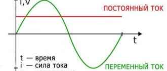
The owner of an apartment or private house who decides to carry out any procedure related to electricity, be it installing a socket or switch, hanging a chandelier or wall lamp, is invariably faced with the need to determine where the phase and neutral wires are located at the place of work, as well as the grounding cable. This is necessary in order to correctly connect the mounted element, as well as to avoid accidental electric shock. If you have some experience working with electricity, then this question will not confuse you, but for a beginner it can be a serious problem. In this article we will understand what phase and zero are in electrics, and we will tell you how to find these cables in a circuit, distinguishing them from each other.
What is the difference between a phase conductor and a neutral conductor?
The purpose of the phase cable is to supply electrical energy to the desired location. If we talk about a three-phase electrical network, then there are three current-supply wires per single zero wire (neutral). This is due to the fact that the flow of electrons in a circuit of this type has a phase shift of 120 degrees, and the presence of one neutral cable in it is quite sufficient. The potential difference on the phase wire is 220V, while the zero wire, like the ground wire, is not energized. On a pair of phase conductors the voltage value is 380 V.
Line cables are designed to connect the load phase to the generator phase. The purpose of the neutral wire (working zero) is to connect the zeros of the load and the generator. From the generator, the flow of electrons moves to the load along linear conductors, and its reverse movement occurs through neutral cables.
The neutral wire, as mentioned above, is not energized. This conductor performs a protective function.
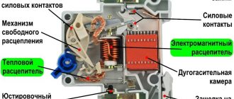
The purpose of the neutral wire is to create a chain with a low resistance value, so that in the event of a short circuit, the current is sufficient to immediately trigger the emergency shutdown device.
Thus, damage to the installation will be followed by its rapid disconnection from the general network.
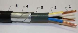
In modern wiring, the sheath of the neutral conductor is blue or light blue. In old circuits, the working neutral wire (neutral) is combined with the protective wire. This cable has a yellow-green coating.
Depending on the purpose of the power transmission line, it may have:
- Solidly grounded neutral cable.
- Insulated neutral wire.
- Effectively grounded neutral.
The first type of lines is increasingly used in the design of modern residential buildings.
In order for such a network to function correctly, the energy for it is generated by three-phase generators and is also delivered through three phase conductors under high voltage. The working zero, which is the fourth wire, is supplied from the same generator set.
Visually about the difference between phase and zero in the video:
How should grounding be carried out in a three-wire network?
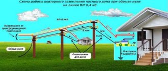
At the moment, in most new buildings, a three-wire network is installed, in which there is a phase, neutral and grounding (yellow-green wire). “Zero” and “ground” are connected in the shield to one grounding bus, but not under a common contact clamp ( PUE 7.1.36 ). The ground is then connected to each outlet in one continuous wire. Most modern electrical equipment already has a third grounding pin on the plug, which provides grounding to the chassis when it is plugged into an outlet.
What is a grounding cable for?
Grounding is provided in all modern electrical household devices. It helps reduce the current to a level that is safe for health, redirecting most of the flow of electrons to the ground and protecting the person touching the device from electrical shock. Also, grounding devices are an integral part of lightning rods on buildings - through them, a powerful electric charge from the external environment goes into the ground, without causing harm to people and animals, or causing a fire.
To the question - how to identify a grounding wire - one could answer: by the yellow-green sheath, but color marking, unfortunately, is often not observed. It also happens that an electrician who does not have sufficient experience confuses a phase cable with a neutral cable, or even connects two phases at once.
To avoid such troubles, you need to be able to distinguish conductors not only by the color of the sheath, but also in other ways that guarantee the correct result.
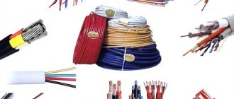
Wiring colors as a way to speed up installation
The correct coloring of the wiring speeds up the installation of electrical wiring.
Before GOST R 50462-2009 came into effect, cables were marked white or black. The phase and zero were determined when the control switch was turned off at the moment of power supply.
The use of color markers simplifies repair work, ensures safety and convenience. Based on the shade of the cables, the master will not spend much time connecting electricity to a house or apartment.
You can consider the meaning of color marking using the example of a lamp. If the lamp is changed and the zero and phase are reversed, there is a risk of injury or death from electric shock. When in electrics the designation L and N is made by color, the phase will go to the switch, and zero will go to the light source. The voltage will be neutralized, and you will be able to touch even a light bulb that is on.
Home electrical wiring: finding zero and phase
You can determine at home where which wire is located in different ways. We will analyze only the most common ones that are accessible to almost anyone: using an ordinary light bulb, an indicator screwdriver and a tester (multimeter).
About the color marking of phase, neutral and ground wires in the video:
Checking with an electric lamp
Before you begin such a test, you need to assemble a testing device using a light bulb. To do this, it should be screwed into a cartridge of suitable diameter, and then secured to the wire terminal, removing the insulation from their ends with a stripper or an ordinary knife. Then the lamp conductors must be applied one at a time to the cores being tested. When the lamp lights up, it will mean that you have found a phase wire. If you check a cable with two cores, it is already clear that the second one will be zero.
Checking with an indicator screwdriver
A good assistant in work related to electrical installation is an indicator screwdriver. The operation of this inexpensive instrument is based on the principle of capacitive current flowing through the indicator body. It consists of the following main elements:
- A metal tip shaped like a flathead screwdriver that is applied to wires for testing.
- A neon light bulb that lights up when current passes through it, thus signaling phase potential.
- A resistor to limit the amount of electrical current that protects the device from combustion under the influence of a powerful flow of electrons.
- A contact pad that allows you to create a circuit when you touch it.
Professional electricians use more expensive LED indicators with two built-in batteries in their work, but a simple device made in China is quite accessible to anyone and should be available to every home owner.
If you check the presence of voltage on the wire using this device in daylight, you will have to look more closely during the work, since the glow of the signal lamp will be difficult to see.
When the screwdriver tip touches the phase contact, the indicator lights up. In this case, it should not light up either at the protective zero or at the grounding, otherwise we can conclude that there are problems in the connection diagram.
When using this indicator, be careful not to accidentally touch a live wire with your hand.
About determining the phase clearly in the video:
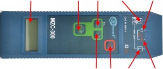
Checking with a multimeter
To determine the phase using a home tester, you need to put the device in voltmeter mode and measure the voltage between the contacts in pairs. Between the phase and any other wire, this indicator should be 220 V, and applying probes to the ground and protective zero should show the absence of voltage.
Additional information about finding the ground, phase, neutral wire
Let's add another method - it is prohibited by industry. A light bulb in a socket with two exposed wires. Using the tool, the phase is found, and the wire can be short-circuited to ground. You cannot use water, gas, sewer pipes or other engineering structures. According to the rules, the cable antenna braid is equipped with grounding (grounding). With respect to it, you can use a tester (a light bulb in a socket prohibited by standards) to find the phase.
For determined people, we recommend fire escapes and steel tires for lightning rods. You need to clean the metal until it shines, call the phase phase
Please note that not all fire escapes are grounded (although they must be), lightning rod buses are 100%. If you discover such blatant arbitrariness, you can contact the management organizations; if there is no response, knock (Russians call human rights activists informers) to government agencies
Indicate a violation of the rules for protective grounding of buildings.
Laying rules
Before proceeding with installation, you need to familiarize yourself with the rules that apply to PE laying:
- There must be no devices in the line that could cause disconnection or disruption of the circuit integrity, for example, removable inserts, switches, circuit breakers and fuses.
- All equipment and live parts are connected directly to protective grounding.
- It is prohibited to connect several electrical devices using the loop principle.
- A separate terminal (clamp) is allocated on the PE distribution bus. It is prohibited to simultaneously connect the neutral protective and working wires to the same terminal.
Connection diagrams for neutral wire and grounding
Now you know how to distinguish the neutral wire from the ground and understand that both are connections to the ground. Now you can consider possible schemes for connecting the neutral wire and grounding. All of them are clearly specified in clause 1.7.3 of the PUE. We will consider only circuits with a solidly grounded neutral that are used in our electrical networks.
The photo shows the TT system
So:
- First of all, let's consider a CT system in which the neutral wire is connected to the grounding of the transformer, and the grounding to an independent source. This method is used very rarely, and the cost of installing such a system is the highest.
- Much more commonly used are TN type systems that use PEN conductors. That is, along the entire length or in certain sections, the neutral and protective conductors are laid with one wire, or are connected to one grounding point.
TN-S system
- The most optimal in this case in matters of electrical safety is the TN-S system. In it, the neutral and protective conductors are connected to a single grounding point, but along their entire length they are made of separate conductors.
TN-C system
- Much more often you can find the TN-C system, which is quite easy to implement with your own hands. In it, the neutral wire and grounding are made of one wire along the entire length. But this is the least safe option in terms of electrical safety.
TN-CS system
- And the last possible option is the TN-CS system. As the name implies, it combines the two previous systems. That is, in one section the neutral and grounding are laid together, and in the second section they are separated.
Reaction of electrical appliances to zero loss
If the common neutral wire in a multi-story building breaks, consumers will feel it as a result of a voltage surge in their electrical appliances.
The main factors that can lead to loss of power to the common zero:
- emergency situation at the substation;
- outdated wiring;
- The wiring installation was not done very well.
The phase to which more consumers of the apartment building are connected will be overloaded. The tension in it will decrease. In the phase to which the least number of consumers are connected, the voltage will increase sharply.
This will have a negative impact on the devices - a decrease in voltage will cause them to operate ineffectively, and an increase in voltage may lead to the failure of those that are currently connected. To protect yourself from such a situation, you need to install an individual surge suppressor in the panel that supplies a separate apartment. As soon as the voltage begins to exceed permissible values, the limiter will quickly turn off the power.
If a zero break occurs directly in the apartment, the electricity will be lost completely, but at the same time the phase will not be turned off. The danger is that it can go right to the neutral wire. And if any electrical device was previously grounded to it, the body of this electrical device will be energized, or, more simply put, it will begin to “beat with current.”
The main factors that contribute to the loss of zero directly in the apartment can be called:
- unreliable connection of contacts;
- incorrectly selected conductor cross-section;
- outdated wiring.
These factors lead to excessive heating of the conductor. Due to the increased temperature, the place where the contacts are connected oxidizes, and the wire strands overheat. And this, in turn, can lead to a fire.