7.54. When using a steel building frame for a project, grounding the neutrals of transformers, as well as equipment housings and electrical structures, should be done by welding a grounding conductor to a building column or building structures connected to the building frame; builders must give a certificate for hidden work on connecting foundation reinforcement with anchor bolts.
7.55. When using a reinforced concrete frame of a building in the grounding circuit, acts must be drawn up for hidden work, if the connections are monolid, or an act for making connections in accordance with the project, if the connections are visible (the latter can be noted in the passport for the grounding device).
The connection of the transformer zero to the embedded product is carried out by welding the grounding conductor to the embedded element of the column or foundation. Grounding of electrical equipment housings and electrical structures should be carried out by welding to embedded products on columns. It is prohibited to weld the grounding conductor to the wall panel reinforcement.
Similar installation requirements must be observed when using trestles as a grounding device.
7.56. Before the installation of artificial grounding conductors at the site begins, the construction organization must complete and hand over all construction work according to the certificate.
7.57. Work on the installation of artificial grounding conductors must be carried out to the extent provided for by the project, in the following sequence:
1) mark the lines for laying conductors, determine the locations of passages and bypasses;
2) drill or punch holes for passages through walls and ceilings;
3) install supports, lay and secure pre-painted grounding conductors or secure conductors using shooting (for dry rooms);
4) connect the conductors to each other by welding;
5) paint the junctions of the conductors.
7.58. Parts of grounding lines and their transportable components (mounting supports, jumpers and other grounding conductors) are manufactured in electrical assembly workshops. Strip or round steel used as grounding conductors must first be straightened, cleaned and painted on all sides.
7.59. Painting of the joints must be done after welding the joints; for this, in dry rooms with a normal environment, oil paints and nitro enamels should be used; in damp rooms and in rooms with a chemically active environment, painting should be done with paints that are resistant to chemical influences. Grounding conductors are painted yellow-green by sequentially alternating yellow and green stripes of the same width from 15 to 100 mm each. The strips must be adjacent to each other or along the entire length of each conductor, or in each accessible location, or in each section.
7.60. Grounding conductors must be laid horizontally or vertically; they can also be laid parallel to inclined building structures. Laying flat grounding conductors on brick and concrete foundations should be done primarily using a construction gun. In dry rooms, grounding strips can be laid directly on brick and concrete foundations. In damp and especially damp rooms and in rooms with chemically active substances, the laying of grounding conductors should be done on supports.
Supports for fastening grounding conductors must be installed maintaining the following distances, mm:
On turns (from the tops of corners). 100
From branch points. 100
From the bottom surface of removable channel covers. 50
From the floor level of the premises. 400 - 600
As supports, embedded products in reinforced concrete foundations and grounding busbar holders K188 are used (Fig. 7.1.).
K188 grounding busbar holders are used for attaching grounding conductors made of round steel with a diameter of 10.12 mm and strip steel with dimensions of 40´4 and 25´4 mm to walls and metal structures. The holders are secured by shooting or welding, have a climatic version of V category 2, weight 1000 pcs. - 75 kg.
The distance from the base surface to the grounding conductors must be at least 10 mm (Fig. 7.1.).
The holders are attached to embedded products located in the concrete base using welding, which is performed around the perimeter of the holder shank, as well as using pistol dowels. The holders are attached to concrete, brick and other bases using pistol dowels, in special cases - using dowels with a spacer nut or nylon spacer dowels. The dimensions of the dowels are given in table. 7.8 - 7.10., the distances between the fastenings of grounding conductors on straight sections are indicated in table. 7.11.
Rice. 7.1. Ground bar holder:
a - for steel round busbars of grounding conductors; b
- for rectangular grounding conductors
Recommended sizes of dowels for attaching grounding conductors
| TO0000026′> | Material and thickness of the target part, mm | Recommended dowel |
| Heavy concrete and reinforced concrete | Steel thickness 1 - 4 | DGPSH 4.5´40 |
| Unplastered brickwork, plastered heavy concrete and reinforced concrete | Same | DGPSH 4.5´50 |
| Plastered brickwork, lightweight concrete and reinforced concrete | » » | DGRSh 4.5´60 |
7.61. To ground product cases and connect grounding conductors, the following types of grounding clamps are used: ZSh - clamp with a pin (Figure 7.4); ЗБ - clamp with bolt (Fig. 7.5); ZV - clamp with screw (Fig. 7.6); ZVP - a clamp with a screw soldered to the support for grounding the sheath and armor of cables (Fig. 7.7); ZSh2P - clamp with two pins and plates (Fig. 7.8); ZSh2S - clamp with two studs and a bracket (Fig. 7.9); ZBKh - clamp with a bolt with a clamp (Fig. 7.10); ZB2 - clamp with two bolts (Figure 7.11).
Circuit location
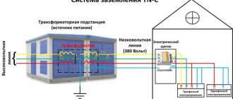
As a rule, grounding conductors are made of a metal strip or rod. The system includes external and internal circuits. Outside the building, the grounding strip is attached to electrodes buried in the ground at a distance of at least 1 m from the foundation and forming a grounding loop. Most often the contour has a triangular shape, but it can be laid in a line or around the perimeter of the building.
The installation depth is determined by the degree of soil freezing and is at least 0.5-0.7 m. A shallower depth is possible at the entrance to the building, where conductor entries are usually enclosed in metal pipes. It is recommended to lay horizontal grounding strips edge-on at the bottom of the trench. Their length is determined by the size of the contour and the distance to the building.
The external circuit is subject to atmospheric and underground corrosion. Destruction of the surface of conductors and fittings gradually reduces the effectiveness of protection. Painting underground parts of the grounding system is not recommended.
They are made from stainless steel and protective copper and zinc coatings. Inside the premises, a metal strip is laid openly along the building structures. In case of high humidity, a bracket for fastening the grounding strip is used.
What does circuit resistance depend on?
The grounding terminal can show different values of grounding resistance - the total value is the sum of a set of parameters, including resistance on individual wires, a common busbar, and the ground contour. The value of these parameters decreases if metal parts have low resistance with high conductivity. An important parameter is the resistance of the soils through which currents flow (the lower it is, the better). Standards for maximum permissible values:
- for buildings with networks of 220, 380V - 30 Ohm;
- for generators, transformer substations – 4 Ohm.
Table of resistances by soil type.
Soils Ohm/m2 Granite stone 2000 Limestone 5050 Basalt 2000 Homogeneous gravel 800 Gravel with clay 300 Sandstones 1000 Wet pressed sandstone 800 Chernozem 200
The degree of soil conductivity increases sharply with increased soil moisture. It is necessary to take this into account when arranging a grounding system. Other parameters are the depth of the circuit, the materials used to manufacture the working parts, dimensions, and the number of electrodes. Elements of the grounding system are placed in the main busbar. Trouble-free operation of installations largely depends on the selected material and compliance with installation rules.
Rolled steel
The grounding bus must have high electrical conductivity, ductility and good weldability. A steel strip is predominantly used as a flat conductor in systems for grounding and potential equalization. This universal type of rolled metal has a rectangular cross-section without internal voids and a flat shape. The strip is manufactured in accordance with GOST 103-2006 “High-rolled hot-rolled steel strip” and has a number of valuable qualities:
This standard specifies general-purpose rolled steel with a thickness of 4 to 80 mm and a width of 10 to 200 mm. Depending on the purpose, strips of measured, multiple and unmeasured lengths are made. The specifics of steel rolling determine the requirements for the length of the rolled product. Strips made from ordinary steels are supplied in lengths of up to 12 m, from alloyed ones – up to 6 m. The minimum length is also regulated; for all types it is 2 m. Rolled steel has the advantage that the number of welded joints when used in a circuit is reduced.
The strip can be of normal or increased precision rolled. But this parameter, like the accuracy of angles or crescent shape, has virtually no effect on the quality of grounding and is not significant when choosing.
What does grounding consist of?
Take a closer look at these components.
External or outer contour
The installation of the ground loop depends on external conditions. Before starting the calculation and completing the design drawing, you need to know the parameters of the soil in which the ground electrodes will be installed. If you have built a house yourself, these characteristics are known. Otherwise, it is better to call surveyors to obtain an opinion on the soil.
What types of soils are there, and how do they affect the quality of grounding? Approximate resistivity of each soil type. The lower it is, the better the conductivity.
This is the best environment to install an external ground loop. The current flow resistance will be quite low even with low moisture content. And in these soils the natural humidity is usually above average.
The resistance is slightly higher, but at normal humidity the grounding parameters will not exceed the standards. If there is prolonged dry weather in the installation region, it is necessary to take measures to forcibly moisten the installation sites of ground electrodes.
Gravel, rock, dry sand - even with high general humidity, grounding in such soil will be ineffective. To comply with standards, deep grounding will have to be installed.
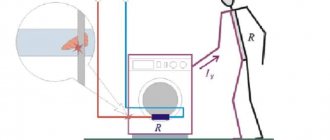
Important! Incorrect calculation of the grounding loop, ignoring the parameters, often lead to disastrous results: electric shock, equipment failure, cable fire.
Many facility owners, saving on matches, simply do not understand why a grounding loop is needed. Its task, when connecting a phase to the ground, is to ensure the maximum value of the short circuit current. Only in this case will the protective shutdown devices operate quickly. This cannot be achieved if the current flow resistance is high.
Galvanized
To extend the service life and protect from environmental influences, a zinc coating is applied to the steel in accordance with GOST 9.307-89 “Hot zinc coatings”. The steel strip is pre-treated and immersed in a container with molten zinc. The coating thickness is 40-200 microns. The thicker the layer, the more it contributes to increasing the strength of the product. The coating is strengthened by repeated immersion of the strip in molten zinc.
Galvanization is currently the most effective and cheapest method of protection. Coating increases the cost of rental, but its service life increases. The properties of zinc are preserved even with minor surface damage. The galvanized strip is resistant to corrosion, elastic, does not crack and has a neat appearance. It is produced from carbon and low-alloy steel grades by slitting steel sheets and is supplied in the form of coils weighing 50-60 kg or rods 5-6 m long.
According to the PUE, the minimum cross-section of the grounding conductor for installations with voltages less than 1 kV is 75 mm2. 4x20 mm strip is the most economical solution that meets these requirements. More often, a galvanized strip with a cross section of 4x40 mm, 5x40 mm, 5x50 mm is used to make a grounding loop. These products ensure compliance with standards and are convenient for grounding installation. According to the standard, one meter of 4x40 mm strip weighs about 1.3 kg. The weight of a linear meter is also regulated by GOST 103-2006 and is used to calculate the required amount of tape.
Copper
Along with galvanized strips, grounding strips with copper coating are widely used in practice.
Copper is less electrochemically active than steel and zinc. Therefore, it lasts longer and can be used in more difficult conditions. Copper-bonded grounding conductors have good ductility. They are supplied in unmeasured lengths, which is convenient for laying grounding loops. Copper strip is also used for the internal circuit as a main conductor used to connect equipment to it. The disadvantage of copper-plated grounding strips is their high price.
What is a ground bus
The grounding bus is installed on the input panel. It connects the wires coming from:
- protective house grounding;
- Electricity consumers;
- metal structures;
- housings and casings of electrical equipment.
A protective conductor PEN is connected to the grounding bus, which is connected to the VLI. Nuts and bolts are used to connect the working parts, but welding will be required to solve some problems. An example is welding a grounding conductor from plates and corners, as opposed to simply screwing it on, which ensures reliable contact between the parts. In factory-made copper pin-type grounding conductors, laser cutting is used, processing, and cutting metal with your own hands at a high level is impossible.
Inner circuit routing
Electrical equipment that must be grounded is located throughout the entire area of the production premises. It is connected to the grounding system by laying busbars inside the building. The installation of grounding conductors is done openly; there should always be free access to them for control and inspection. The exception is metal pipes for hidden electrical wiring and explosive installations, where openings are sealed with easily knocked out non-combustible materials.
The grounding strips of the internal circuit should be laid horizontally or vertically. Only if the building includes inclined structures, it is allowed to lay conductors parallel to them. The internal grounding loop is mounted using walls and ceilings; if it is necessary to lay it on the floor, the grounding strip is laid in channels. Rectangular conductors are mounted with a wide plane to the wall. The strip is fastened to brick and concrete surfaces by driving nails using a construction gun. Screws are used for fixing to wooden walls. The grounding conductors are connected to each other by welding. With strong heating, the protective zinc coating evaporates, thereby reducing the resistance of the steel to external influences. Therefore, the connection points are treated with zinc spray or enamel. In places where the resistance of the grounding device is to be measured, the conductor is bolted. It should be removable, but only with a tool. The attachment points of the grounding strips should be at a distance of 650 mm to 1000 mm from each other. The larger the cross-section of the strip, the more frequently they are located.
The structure of a building may include expansion joints that protect it from deformation. The grounding strip crossing such a joint must have a compensating bend. Through walls and ceilings, the grounding strip is freely passed through openings or enclosed in a steel pipe.
Mounting on brackets
Fastening directly to walls is only permitted in rooms with a dry, non-aggressive atmosphere. If there is a large amount of moisture and caustic vapors in the air, grounding conductors should be welded to the supports. The distance to the wall must be at least 10 cm. Grounding busbar holders are made of steel, they are secured with pistol dowels or welded to bookmarks embedded in the wall. On complex surfaces, dowels with an expansion nut or nylon expansion dowels are used. The distance between supports should be from 600 mm to 1000 mm in a straight line, at corners of 100 mm from the turning point. The recommended height at which the bracket should be placed is 400-600 mm from the floor level.
Grounding conductors are painted along their entire length with yellow and green stripes adjacent to each other. The color stripes must have the same width; for tires it is set in the range of 15-100 mm.
Grounding plays an important role in protecting people and property from damage. Thanks to it, sudden events such as lightning or a short circuit will not lead to casualties or damage to material assets.
The use of a steel strip as a grounding conductor has proven itself in practice and is considered effective and profitable.
Source
How to attach a grounding strip to the wall of a building
Protective grounding is the deliberate connection to the ground of metal parts of an electrical installation that are not energized (disconnector drive handles, transformer casings, support insulator flanges, instrument transformer housings, etc.).
Installation of grounding devices consists of the following operations: installing grounding conductors, laying grounding conductors, connecting grounding conductors to each other, connecting grounding conductors to grounding conductors and electrical equipment.
Vertical grounding rods made from angle steel and rejected pipes are immersed in the ground by driving or pressing, and from round steel - by screwing or pressing. This work is carried out using mechanisms and devices, for example: a copra (driving into the ground), a device for a drill (screwing rod electrodes into the ground), a PZD-12 mechanism (screwing grounding electrodes into the ground).
For grounding devices, the most common are electric deepeners that have a standard electric drill and a gearbox that reduces the rotation speed below 100 rpm and accordingly increases the torque on the screwed-in electrode. When using these deepeners, a spigot tip is welded to the end of the electrode, which loosens the soil and facilitates immersion of the electrode. The commercially produced tip is a steel strip 16 mm wide, pointed at the end and bent along a helix. In installation practice, other types of electrode tips are also used.
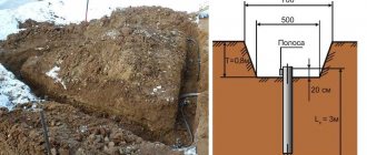
When installing grounding, vertical grounding conductors should be laid to a depth of 0.5 - 0.6 m from the level of the ground level and protrude from the bottom of the trench by 0.1 - 0.2 m. The distance between the electrodes is 2.5 - 3 m. Horizontal grounding conductors and connecting strips between vertical grounding conductors are laid in trenches 0.6 - 0.7 m deep from the level of the ground level.
All connections in the grounding circuits are made by lap welding; Welding areas are covered with bitumen to prevent corrosion. The trench is usually dug 0.5 m wide and 0.7 m deep. The construction of the external grounding loop and the laying of the internal grounding network are carried out according to the working drawings of the electrical installation project.
Grounding conductors are introduced into the building in at least two places. After installing the grounding devices, an act for hidden work is drawn up, indicating on the drawings the connection of grounding devices to stationary landmarks.
Grounding main conductors are laid along the walls at a distance of 0.5-0.10 m from the surfaces at a height of 0.4-0.6 m from the floor level. The distance between the fastening points is 0.6 -1.0 m. In dry rooms and in the absence of a chemically active environment, it is permissible to lay grounding conductors close to the wall.
Grounding strips are secured to the walls with dowels, which are fired with a construction gun either directly to the wall or through intermediate parts. Embedded parts to which grounding strips are welded are also widely used. Using a PTs-type gun, you can shoot parts made of sheet or strip steel up to 6 mm thick into foundations made of concrete (grade up to 400), brick, etc.
In damp, especially damp rooms and in rooms with caustic fumes (aggressive environment), grounding conductors are welded to supports secured with dowels-nails. To create a gap between the grounding conductor and the base in such rooms, a stamped holder made of strip steel with a width of 25 - 30 and a thickness of 4 mm is used, as well as a bracket for laying round grounding conductors with a diameter of 12 - 19 mm. The overlap length during welding should be equal to twice the strip width for rectangular strips or six diameters for round steel.
Grounding conductors are connected to the pipelines; if there are valves or bolted flange connections on the pipes, bypass jumpers are made.
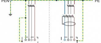
Parts of electrical installations to be grounded are connected to grounding lines with separate branches. Steel grounding conductors are connected to metal structures by welding, and to equipment - possibly by welding. grounding bolt or where the conductors are connected to copper conductors with fastening by wire banding and soldering. A common grounding loop is usually made around the substation, to which the grounding conductors of the interior of the substation are welded. Individual elements of electrical equipment are connected to grounding conductors in parallel, and not in series, otherwise, if the grounding conductor breaks, part of the equipment may become ungrounded.
Circuit location
As a rule, grounding conductors are made of a metal strip or rod. The system includes external and internal circuits. Outside the building, the grounding strip is attached to electrodes buried in the ground at a distance of at least 1 m from the foundation and forming a grounding loop. Most often the contour has a triangular shape, but it can be laid in a line or around the perimeter of the building.
The installation depth is determined by the degree of soil freezing and is at least 0.5-0.7 m. A shallower depth is possible at the entrance to the building, where conductor entries are usually enclosed in metal pipes. It is recommended to lay horizontal grounding strips edge-on at the bottom of the trench. Their length is determined by the size of the contour and the distance to the building.
The external circuit is subject to atmospheric and underground corrosion. Destruction of the surface of conductors and fittings gradually reduces the effectiveness of protection. Painting underground parts of the grounding system is not recommended.
They are made from stainless steel and protective copper and zinc coatings. Inside the premises, a metal strip is laid openly along the building structures. In case of high humidity, a bracket for fastening the grounding strip is used.
Work technology
We select the location of the grounding conductors. Of course, not far from the house (facility), so that you do not have to lay a long conductor, which will have to be mechanically protected. It is advisable that the entire contour area be located on the territory that you control (you are the owner). So that one fine moment, your protective “ground” will not be dug up by a drunken excavator operator. So we won’t hammer in the pins behind the fence.
A vegetable garden (with the exception of a potato bed), a front garden, or a flower bed near the house will do. Cultivated areas are preferable and are regularly watered. And additional moisture in the ground will benefit grounding. If your soil has low resistivity, you can install grounding on the site, which will then be covered with asphalt or tiles. Under artificial turf, the ground does not dry out. And the risk of damaging the ground loop is minimal.
Of course, future plans must be taken into account. If a garage with an inspection hole appears in the place where the circuit is installed in a year, it is better to immediately choose a quieter place.
Depending on the shape of the site, we choose the order of arrangement of the electrodes: in a line or in a triangle.
Important! Regardless of the location, there must be at least three vertical grounding conductors.
If a triangle is selected, we mark out a site of the appropriate shape with sides of 2.5–3 meters. We dig a trench in the shape of an equilateral triangle to a depth of 70–100 cm, a width of 50–70 cm. We know that all ground electrodes are connected to each other. The conductor must be deepened to a distance of at least 50 cm, taking into account the minimum ground level (for example, digging a bed). If a coating is laid on top, its thickness is not taken into account. Only clean soil.
You can select all the soil, not just around the perimeter of the trench. The result will be a triangular pit 0.7–1.0 m deep. The finished circuit can be filled with soil with low resistivity. For example, ash or ashes. The salts will penetrate into the ground and will help reduce the overall resistance to current flow.
After which, in the corners of the pit (trench) we begin to hammer in the electrodes.
Parameters of grounding conductors (considering a vertical arrangement)
Rectangle or corner - cross-sectional area 100 mm².
Rectangle or corner - cross-sectional area 75 mm².
Rectangle or corner - cross-sectional area 50 mm².
Important! It is strictly forbidden to drill wells and then immerse ground electrodes into them. With this installation method, the resistance increases significantly.
The soil should tightly adhere to the metal surface of the ground electrode. It is prohibited to paint electrodes!
But what if, according to calculations, the length of each of the three electrodes exceeds 1.5–2 meters? There are little secrets.
Information: it often happens that the ground electrode rests on a monolithic obstacle (for example, at a depth of 2.5 meters), and the calculated depth is 3.5 m. In this case, the electrode is simply cut off, and another rod will be added to the ground loop to compensate for the lost length.
We connect the electrodes with a conductor. If the reinforcement is steel, welding is best. The copper rods are connected with a bolt tie; the conductor must have a cross-section of at least 30% of the cross-section of the electrodes.
After assembling the circuit, we measure the current flow resistance. The grounding loop requirements for individual housing are 10 ohms. It is better to entrust the measurement to certified specialists who have the appropriate equipment. Moreover, when receiving specifications from power engineers, you will still have to provide a grounding system for measurements. If the resistance is higher than normal, we add electrodes and weld them to the circuit. Until we get the norm.
Rolled steel
The grounding bus must have high electrical conductivity, ductility and good weldability. A steel strip is predominantly used as a flat conductor in systems for grounding and potential equalization. This universal type of rolled metal has a rectangular cross-section without internal voids and a flat shape. The strip is manufactured in accordance with GOST 103-2006 “High-rolled hot-rolled steel strip” and has a number of valuable qualities:
This standard specifies general-purpose rolled steel with a thickness of 4 to 80 mm and a width of 10 to 200 mm. Depending on the purpose, strips of measured, multiple and unmeasured lengths are made. The specifics of steel rolling determine the requirements for the length of the rolled product. Strips made from ordinary steels are supplied in lengths of up to 12 m, from alloyed ones – up to 6 m. The minimum length is also regulated; for all types it is 2 m. Rolled steel has the advantage that the number of welded joints when used in a circuit is reduced.
The strip can be of normal or increased precision rolled. But this parameter, like the accuracy of angles or crescent shape, has virtually no effect on the quality of grounding and is not significant when choosing.
Design
The zero bus with grounding can be placed both inside the input device (ISU) and separately from it. In the first case, it is allowed to use an artificially organized PE bus, which has direct electrical contact with the body of the distribution cabinet, as a main switch.
When placed outside the boundaries of the input device, this assembly and distribution structure should be located not far from it (in a place convenient for maintenance and accessible to specialists).
To limit access by unauthorized persons, open grounding bars can be hidden in a locked box, the door of which is marked with a special sign.
According to current regulations (PUE, in particular), the GZSh must be manufactured in the form of a copper or steel strip having certain dimensions. When placed outside the cabinet and in it, they are selected taking into account that the required number of contact holes for bolted connections fits on the bus.
For industrially produced standard products GZSh XX-UHL4 TVS, for example, these dimensions are strictly standardized and selected from the following range: 3x30, 3x40, 4x40 millimeters. In this case, a suitable rail is selected based on the standardized number of holes for fastening conductors (10, 15 or 20).
The dimensions listed above may differ in size from different manufacturers, but all of them should be considered as parameters of the GZSh, complementing the characteristics already given earlier.
We pay special attention to the fact that the use of aluminum for the manufacture of distribution strips is not allowed. In addition, when choosing a product with given parameters, you should always keep in mind that the dimensions of the main generator cannot be less than the cross-section of the PE bus organized within the boundaries of the ASU.
To this it must be added that the design of the rails should provide for the possibility of connecting additional conductors to them using a suitable tool (a wrench for a bolted connection, for example).
If there are several power line inputs in the building, a grounding bus is installed at each of them. The resulting busbar connection must be connected to potential equalizers.
And finally, when organizing a grounding system, one should not confuse the GZSh with a PE bus, organized with the aim of obtaining re-grounding on the receiving side. Although they have electrical contact, their purpose is different.
You can familiarize yourself with the figure, which shows the appearance and designation of the GZSh.
Galvanized
To extend the service life and protect from environmental influences, a zinc coating is applied to the steel in accordance with GOST 9.307-89 “Hot zinc coatings”. The steel strip is pre-treated and immersed in a container with molten zinc. The coating thickness is 40-200 microns. The thicker the layer, the more it contributes to increasing the strength of the product. The coating is strengthened by repeated immersion of the strip in molten zinc.
Galvanization is currently the most effective and cheapest method of protection. Coating increases the cost of rental, but its service life increases. The properties of zinc are preserved even with minor surface damage. The galvanized strip is resistant to corrosion, elastic, does not crack and has a neat appearance. It is produced from carbon and low-alloy steel grades by slitting steel sheets and is supplied in the form of coils weighing 50-60 kg or rods 5-6 m long.
According to the PUE, the minimum cross-section of the grounding conductor for installations with voltages less than 1 kV is 75 mm2. 4x20 mm strip is the most economical solution that meets these requirements. More often, a galvanized strip with a cross section of 4x40 mm, 5x40 mm, 5x50 mm is used to make a grounding loop. These products ensure compliance with standards and are convenient for grounding installation. According to the standard, one meter of 4x40 mm strip weighs about 1.3 kg. The weight of a linear meter is also regulated by GOST 103-2006 and is used to calculate the required amount of tape.
The color of the ground wire in a three-core wire
In a three-core wire, in accordance with the rules of the PUE, the grounding wire is marked with the letters PE. Its color is yellow-green. Similarly, marking is carried out on four-core or more cables. In imported cables, the color designation is yellow or green. Another distinctive feature is the diameter of the grounding branch. It may be less than that of a phase wire.
The color of the ground wire in a three-core wire
In some cases, the three-core wire contains a limited gap in the transparent insulation. In this case, a limited cable designation is allowed. The minimum distance from the open electrical wire to the insulation is 15 mm.
Copper
Along with galvanized strips, grounding strips with copper coating are widely used in practice. Copper is less electrochemically active than steel and zinc. Therefore, it lasts longer and can be used in more difficult conditions.
Copper-bonded grounding conductors have good ductility. They are supplied in unmeasured lengths, which is convenient for laying grounding loops. Copper strip is also used for the internal circuit as a main conductor used to connect equipment to it. The disadvantage of copper-plated grounding strips is their high price.
Results
In conclusion, we note that a fairly common method of connecting individual elements of the ground bus is welding.
It fully satisfies the GOST requirements for arranging reliable contacts. At the same time, the use of a welding device for assembly purposes ensures a strong connection with a guarantee of high conductivity.
We also note that the quality of bolted connections is ensured by reliable crimping of the cable lugs of the supply wires. In the same way (by bolting) the busbar in the tip is connected to the cabinet body.
Source
Inner circuit routing
Electrical equipment that must be grounded is located throughout the entire area of the production premises. It is connected to the grounding system by laying busbars inside the building. The installation of grounding conductors is done openly; there should always be free access to them for control and inspection. The exception is metal pipes for hidden electrical wiring and explosive installations, where openings are sealed with easily knocked out non-combustible materials.
The grounding strips of the internal circuit should be laid horizontally or vertically. Only if the building includes inclined structures, it is allowed to lay conductors parallel to them. The internal grounding loop is mounted using walls and ceilings; if it is necessary to lay it on the floor, the grounding strip is laid in channels. Rectangular conductors are mounted with a wide plane to the wall. The strip is fastened to brick and concrete surfaces by driving nails using a construction gun. Screws are used for fixing to wooden walls.
The grounding conductors are connected to each other by welding. With strong heating, the protective zinc coating evaporates, thereby reducing the resistance of the steel to external influences. Therefore, the connection points are treated with zinc spray or enamel. In places where the resistance of the grounding device is to be measured, the conductor is bolted. It should be removable, but only with a tool. The attachment points of the grounding strips should be at a distance of 650 mm to 1000 mm from each other. The larger the cross-section of the strip, the more frequently they are located.
The structure of a building may include expansion joints that protect it from deformation. The grounding strip crossing such a joint must have a compensating bend. Through walls and ceilings, the grounding strip is freely passed through openings or enclosed in a steel pipe.
Choosing a location for installing a gas shield
On an overhead line pole
If there is an additional input device in the section where the supply line is connected to the main ASU located at the serviced facility (on a pole, for example), then the GZSh can be mounted directly on it.
The requirements of current regulations (the same PUE, for example) require connecting a grounding bus mounted on a pole to the main distribution strip located in the internal input device.
Also, one should not forget about organizing the re-grounding of the PEN conductor on the pole by separating a separate PE grounding bus from it. The latter means that the specified structural element must be electrically connected to another grounding circuit, installed directly under the support.
In the ASU cabinet
The cabinet with the main busbar mounted in it can be placed directly on the facade of the house in a place previously provided for this. At industrial facilities and in buildings of various organizations, the installation of ASU, as a rule, involves the use of a special panel room for these purposes.
If the switchgear is located outdoors, the cabinet body must have an IP index corresponding to its operating conditions.
Installation of structural elements that implement a functional (working) grounding bus involves a whole set of special operations, during which the following points must be taken into account:
- for ease of installation, the main busbar is bolted to the steel cabinet body;
- during installation, the grounding bus must be connected to the “zero” rail using a steel (copper) jumper;
- its dimensions should be comparable to the cross-section of the protective and neutral working conductors;
- their placement relative to each other is not stipulated in any way by current regulations.
The cross-section of the PE grounding plate must be at least 10 mm2 (if it is made of copper). For a steel conductor this value cannot be less than 75 mm2.
Installation outside the cabinet
Outside the cabinet, the main grounding bar must be installed in places protected from unauthorized access and interference.
It is fixed within the boundaries of a hard flat surface on insulators made of a sufficiently strong material. As an example of open placement of a gas shield, let’s consider the installation of a standard 19-inch plate of the “TLK” brand.
The TLK-ERH-CU grounding bars, widely used in electrical engineering, are a certified product from TLK that meets all previously agreed upon requirements. During their manufacture, 14 to 18 mounting bolts are placed on a copper rail with a standard size of 19 inches (19”) for connecting the supply conductors.
According to the requirements for structures of this class, such a 19-inch rail with 14 (18) connectors should be installed in special cabinets manufactured by the same trading company. And only after this the finished structure is connected to the grounding system using a copper wire of the appropriate section.
Additional Information. The cabinet used to accommodate the 19-inch rail is appropriately designated “No. 19.”
Another option for arranging a grounding bus is to use special DIN rails for these purposes, which fall into the category of standard electrical products combined in one cabinet.
According to current standards (GOST, in particular), a set of such DIN rails can be intended for other purposes (they can be used as strips for connecting phase and neutral conductors).
Installation location
Regardless of where the main grounding bus will be installed, its connections must comply with all the necessary standards of the GOST 10434 system, in the part that relates to the contacts of second-class connections. The design of the conductor rail must be designed to directly connect other conductors and contacts to it.
The main grounding bus must be located in an isolated place (TLK, ShZ-U1 and others). For example, this could be a special durable cabinet or drawer, which is made of bent steel profile. There is always access to this rail through a separate hole in the side if the box is locked. Typically, a nameplate with its parameters is placed on the surface of such a housing. Additional locking devices increase stability and safety for surrounding people.
Typically, protective boxes with the main grounding bus are placed at a height of about 1.5 meters from the floor. This is done in order to make it difficult for children to access them. If there is no lock on the cabinet or it requires replacement, then at such a time there is a possibility that a child, unknowingly, can reach contacts that are energized. This poses a danger to his life.
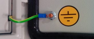
In the installation cabinet, the main grounding bus is located horizontally. It is clamped on the sides with bolts, tightly fastening it to the base. After installation and connection, grounding devices should be painted purple. In industrial buildings, in order to protect high-tech electrical equipment, it is placed in steel electrical cabinets, which are installed in the ventilation system.
Grounding of various electrical equipment is carried out in compliance with GOST standards. They involve the installation of two types of grounding bars: model REC-ET2-M and model REC-ET. REC-ET2-M - mounted using special profiles for electrical cabinets or racks, providing for the simultaneous connection of 14 circuits or more. REC-ET - requires a special organizer, which will allow you to connect and install up to 9 wires.
Good afternoon, dear readers! In the last article, we looked at the potential equalization system of one of the components, which is considered the main grounding bus. It also has the abbreviated name GZSh. In this article you will find complete and detailed information on how to install the main grounding bus yourself in a multi-storey building.
The device of the main grounding bus must necessarily have a cross-section smaller than that of the neutral working or protective conductor. The main ground bus is usually made of the following materials:
The use of aluminum is completely prohibited by the rules of the PUE.
Application of a protective element
Thanks to the bus, you can separate conductors and connect contacts
The main ground bus is a protective equipment. It is used as the main element of the protective circuit for draining lines through residential buildings and industrial buildings. Similar products are used when connecting equipment with voltages up to 1000 V.
The device is a connecting element for several different power consumers. It ensures the operation of the entire grounding system in the building. It must also equalize the potentials in the electrical network. Thanks to the bus, you can separate conductors and connect contacts.
In addition to the main grounding bus, the system includes a set of copper connectors and a structure made of a metal profile or reinforcement, which is the grounding loop. This circuit must be driven into the ground next to the building to ensure reliable contact between the metal and the soil.
Typically, the grounding bus collects conductors coming from the following structures:
- main ground loop;
- pipeline housings, metal equipment;
- lightning rod.
A PEN conductor is also connected to it, which is part of the supply voltage cable.
It is important to consider the grounding system at the stage of designing a house.
Mounting on brackets
Fastening directly to walls is only permitted in rooms with a dry, non-aggressive atmosphere. If there is a large amount of moisture and caustic vapors in the air, grounding conductors should be welded to the supports. The distance to the wall must be at least 10 cm. Grounding busbar holders are made of steel, they are secured with pistol dowels or welded to bookmarks embedded in the wall. On complex surfaces, dowels with an expansion nut or nylon expansion dowels are used. The distance between supports should be from 600 mm to 1000 mm in a straight line, at corners of 100 mm from the turning point. The recommended height at which the bracket should be placed is 400-600 mm from the floor level.
Grounding conductors are painted along their entire length with yellow and green stripes adjacent to each other. The color stripes must have the same width; for tires it is set in the range of 15-100 mm.
Grounding plays an important role in protecting people and property from damage. Thanks to it, sudden events such as lightning or a short circuit will not lead to casualties or damage to material assets.
The use of a steel strip as a grounding conductor has proven itself in practice and is considered effective and profitable.
Before filling the trenches, steel strips or round rods are welded to the external grounding loop, which are then brought inside the building where the equipment to be grounded is located. There must be at least two inputs connecting the grounding conductors to the internal grounding network (internal grounding loop), and they are made of steel conductors of the same sizes and cross-sections as the connection of the grounding conductors to each other. As a rule, grounding conductor entries into the building are laid in fireproof non-metallic pipes protruding on both sides of the wall by approximately 10 mm.
Ground loop inside the object
As a rule, this is a steel bus laid openly along the inner surface of the walls, near the floor.
In individual residential buildings, installation of an internal grounding loop is not carried out. Due to the low hazard class of the premises and the small number of electrical installations. Instead of the internal circuit, a grounding shield, or main grounding bus (GGB), is installed.
The shield is connected either to the internal circuit (as in the illustration) or using a conductor to the external ground circuit. Directly from the panel, protective grounding conductors are routed through electrical installations. Often, instead of a grounding shield, a “PE” contact block can be used, directly in the entrance panel of the apartment.
We examined in detail what a ground loop is, why it is needed, and what it should be according to the PUE. Self-installation does not reduce your responsibility: your life and the lives of your household depend on compliance with safety requirements.
Source