Leakage current is an electric current flowing into the ground, open, third-party conductive parts and protective conductors under normal conditions (definition according to GOST 30331.1-2013 [1]).
Having carried out a very extensive analysis of existing regulatory documentation, Kharechko Yu.V. in his book [2] concludes the following:
“From the definition presented above, it follows that leakage current occurs under normal operating conditions, when the insulation of live parts of a low-voltage electrical installation that are energized is not damaged. Such conditions are called normal conditions. Leakage current flows from live parts into the ground or third-party conductive parts. It should be taken into account that the leakage current of class I electrical equipment usually flows along the following conductive path: from live parts to its open conductive parts and then to the protective conductors connected to them. »
Kharechko Yu.V. also explains the reason for the occurrence of leakage current [2]:
“The active insulation resistance of current-carrying parts of electrical equipment cannot be infinitely large, and their capacitance relative to the ground or conductive parts connected to the ground cannot be equal to zero. Therefore, a small electric current constantly flows from any live part that is energized into the ground, as well as into the conductive parts electrically connected by protective conductors to the grounding device of the electrical installation of the building and to the grounded current-carrying part of the power source, which is called leakage current in regulatory documentation. That is, under normal conditions, there is always an electric current leakage into the ground, open and third-party conductive parts and protective conductors from the live parts of operating electrical equipment. »
There is only one way to eliminate leakage currents - by disconnecting the electrical installation of the building.
How to independently check current leakage using a household multimeter or an indicator screwdriver
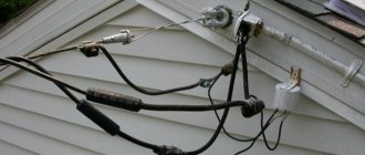
Professional electricians quite often encounter current leakage when inspecting electrical wiring, especially old wiring, electrical appliances of poor quality and other electrical equipment. The problem of leakage current is also quite common in the operation of cars and causes rapid discharge of the battery. This article will discuss actions to identify electricity leaks in relation to a 220V home network, but there are no fundamental differences between it and a car electrical network.
The reasons for current leakage are quite commonplace; over time, the protective insulation of the wire wears out and its characteristics change. If the wiring is used incorrectly, kinks, cracks, and abrasions appear on the wire insulation. The main task of insulating wiring and conductive elements is to protect people from electric shock and prevent leakage of electricity.
Even new electrical appliances and wiring have small current leaks. Almost any insulation is not ideal, especially for cheap cables in the low price category. Cheap electrical wiring, as a rule, has microcracks from the factory, it is less resistant to temperature and humidity changes, and small thickness defects are often found. Improper operation, overheating of the wire at loads exceeding the design ones - all this damages the insulation and leads to current leaks.
Current leakage can be determined by the following characteristic signs: touching the body of an electrical appliance, a wall, or a pipeline causes a slight tingling sensation in the fingertips. But be careful - a leakage value not exceeding 10 mA is considered safe, but a leakage current of more than 30 mA is deadly.
If you suspect a current leak, you must immediately turn off the power to the room and call professionals. A car with significant leaks is also unsafe to operate. The second sign of current leakage is increased consumption disproportionate to use and, as a result, large electricity bills or discharge of the battery in the car.
What devices can detect electricity leaks?
Electrical laboratory specialists use a professional device for measuring insulation resistance - a megohmmeter. Such devices are quite expensive and are not used in everyday life.
In many homes or garages, you can find a household multimeter and an indicator screwdriver, and with them you can independently locate the location of a current leak or an electrical appliance with defective insulation.
In order to check the insulation resistance of an electrical appliance using a “household multimeter”, it is necessary to completely disconnect the device being tested from the power supply. On the multimeter, set the regulator to the 20 MΩ position. Touch the pin of the plug with one probe, and the metal part of the electrical appliance with the other, it is better to sequentially in several places. If the number “1” is displayed on the display, then there is no leakage current, the insulation is working properly, indicators on the screen below one indicate leakage currents and the lower the indicator, the greater the leakage current.
If you do not have a multimeter, then you can detect a leak with a regular, even the cheapest indicator screwdriver. Modern indicators are sensitive even to small currents. The algorithm of actions is even simpler; you need to plug in the device and touch the tip of the screwdriver to the metal parts of the device, pipeline or walls in several places. It is better to pre-shade the room; if there is a leakage current, the indicator will light up with varying degrees of intensity.
How to find a leak in electrical wiring or cable
It is impossible to find an insulation defect in hidden wiring without special equipment. In this case, it is necessary to call specialists from an electrical engineering laboratory. When open, you can visually carefully inspect the wire for damage to the insulation, especially in places where the cable comes into contact with walls, risers, and metal parts.
Why is a leak dangerous?
Electric shock to a person
If the insulating layer loses resistance, a person touching the body of a household appliance, the sheath of a wire, a plug-type plug, a socket, a water supply or heating pipe, or the walls of a residential building will act as a conductor. Through his body, the leakage current will flow into the ground. There are risks of partial damage or death.
Current leakage will affect the quality of power consumption. Some consumers may not be working in the house, but even if the equipment is turned off, the electricity consumption will be reflected on the electricity meter.
Grounding electrical appliances will prevent electric shocks when touching the body. In this case, the fixation point of the conductive cable will begin to intensively generate heat, which will cause a fire in the wiring.
Finding the cause of current leakage
There are several reasons for current leakage in a car. These may be regular problems with the factory equipment that was installed during the construction of the car. These include:
- wiring;
- audio system;
- generator;
- alarm;
- starter.
But standard leaks appear less frequently and mainly due to the high mileage of the vehicle.
Non-standard devices include those devices that the driver additionally installed on the car. For example, this could be a video recorder, a navigator, an alarm system and a non-factory radio, as well as cameras and radar detectors.
Therefore, when the test readings are above 80 mA, it is important to find a current leak. First of all, you need to check the following points:
- Determine which battery is worth. If it is old, then current leakage is normal for a worn-out device.
- Check that the headlights, dimensions and car radio are turned off.
- Look at the wiring insulation, it may be the cause.
- Possible heavy dust on the contact terminal blocks or on the sockets to which devices in the car are connected. Due to the large layer of dust, they could oxidize.
- Negligence in installing additional devices, which led to a short circuit.
- Metal fasteners damaged the wiring.
- Melted wires that are close to the motor.
If all these points have been checked and no problems are found, then the problem may be the formation of salt deposits on the circuit with a thick starter wire as a result of water accumulation. This problem is also possible with the generator wiring. The battery itself also gets dirty on top.
On a note!
If there are problems with the insulating layer of the electrical wiring, spontaneous combustion is possible!
If the problem cannot be detected, it is recommended to conduct a full diagnosis of the generator. To do this, you need to measure the voltage on the battery. This is done as follows:
- turn off the engine;
- two terminals from the battery are removed;
- connect the multimeter: the black probe of the device is negative, and the red probe is positive;
- with a charged battery, the value should be 12.5–12.9 V.
After the procedure, the terminals are returned to their place and the engine is turned on. After this, we turn on the heated glass, climate control and side lights. This is necessary to load the generator. Reconnect the multimeter to the battery. The reading should be between 13 and 13.3 V. A maximum reading of 14.3 V is possible.
If the indicator does not exceed 13.8 V, then most likely the cause of the leak is in the generator. Then it’s best to go to a service center and do a full diagnosis. If the indicators correspond to the required range, then the cause of the leak is in the network itself.
How to find a problem with electrical wiring
Most often, in modern apartments and houses, owners install hidden electrical wiring in the walls. To detect a problem in a wall hidden under plaster or wallpaper, you can use a transistor radio.
First, you must turn off all electrical consumption devices to eliminate noise. Afterwards, you need to walk with the radio on along all the walls with hidden wiring. At the location of the problem, the characteristic noise of the receiver will be heard.
Current testing
To begin with, we determine what kind of current flows in the circuit - alternating or direct. The choice of the socket for the black probe, from the “10 A” or “VΩmA” options, is made after specifying the approximate parameters in Amperes. The procedure is largely identical to the one discussed above. If, after connecting to the connector with the maximum current value, the display shows a significantly lower value, place the plug in another socket. When re-displaying smaller parameters, we stop at the range with a lower amperage.
It is important to remember that the connection of the device in the circuit in this case is also carried out exclusively in parallel
ABS sensor
It is checked by two parameters: voltage and resistance.
To start measuring, select the appropriate mode on the multimeter. If you want to know the resistance value, for most the norm is 1.2-1.8 kOhm. Connect the device to the sensor and start taking measurements. At the same time, shake the wires going to the element. If the numbers on the screen change and become higher or lower than normal, there is a problem with the sensor.
Measuring voltage is a little more difficult - this can only be done with a jack or in a car service on a stand. You need to spin the car wheel to 40-50 rpm and monitor the multimeter readings. On any machine it should output 2 volts.
What to do after discovering a leak
- Since it is unsafe to use an electrical appliance that has leakage current, the fault is eliminated. Wiring with damaged insulation must be replaced; simply wrapping it with electrical tape is a temporary measure.
- If the cause of the insulation failure was a fastening element (a pinched metal clamp), the installation method must be changed.
- If leakage is detected in the contact groups, it is enough to eliminate the cause of the increased humidity.
- If the reason for the violation of the integrity of the insulation is vibration (for example, the wire of a refrigerator or washing machine), it is necessary to rearrange the electrical appliance.
After eliminating the problems and causes of insulation failure, it is necessary to re-measure the leakage current immediately after the work. Then, on problematic electrical appliances, measurements are carried out regularly, at least once a month.
Voltage measurements
For a network with alternating voltage, the switch arrow is set to ACV. Probes are connected to the COM and “VΩmA” connectors. If you are unsure of the approximate range of the voltage being tested, select the maximum value. When a value less than the set value appears on the display, the switch is switched to a lower voltage level. Using the selection method, you can quickly determine the approximate value of the desired value. For a constant voltage network, this process is carried out in a similar way. Most often, in the second option, the 20 V mark is selected. An example would be repair work on the electrical equipment of a car.
It is safe to say that such an event does not cause any major difficulties. You just need to adhere to basic safety measures - avoid touching the bare areas of the probes with your hands.
Self-diagnosis with a multimeter
Diagnostics is carried out using a conventional multimeter (tester). Current measurements are carried out in a mass discontinuity or in a “positive” section discontinuity. The mass discontinuity detection scheme is considered safe. To do this you need to do the following:
- The multimeter settings correspond to measuring current readings in amperes (10-20 A);
- Disconnect the negative terminal from the battery;
- Connect one wire of the tester to the battery terminal;
- The other wire of the tester should be on the removed wire.
The polarity may not be observed for the electronic tester. Before starting measurements, turn off the ignition and remove the key.
Detecting a leak in the positive gap involves the following scheme:
- Set the amperes on the device;
- Disconnect “+” from the battery;
- Connect the negative connector of the tester to the disconnected battery terminal;
- Connect the positive connector of the tester to the “-” battery.
If the steps are completed correctly, a current value will appear on the tester screen. Exceeding the norm (15–80 mA) by the found current value indicates a leak. As a result, you need to look for the problematic circuit.
Characteristic signs
Leakage current path through a damaged rectifier diode
You can recognize current leakage by the following signs:
- slight tingling when touching the wall, pipes, household appliances;
- increased energy consumption for no apparent reason;
- starts to knock out plugs when several devices are turned on;
- interference and noise from a working radio;
- electrical appliances do not work when plugged in;
- electric shocks in the bathroom during water procedures.
To eliminate a phenomenon, you need to identify its cause.
How to check current leakage in a car with a multimeter
When the first signs of such a malfunction appear, it is necessary to check the current leakage in the car using a device.
Check sequence:
1. Before performing work, you need to find a diagram of the location of the car's fuses. This can be done by downloading the car's operating manual and asking the appropriate request in a search engine. In some cars, the fuse code is located on the fuse box cover. You need to find all the places where there are fuses in the car.
2. The positive terminal of the battery is removed. The ignition and all electrical equipment of the car must be turned off. Some experts recommend monitoring via the negative terminal. There are no fundamental differences, the circuit is still the same. When monitoring using the positive terminal, it is easier to search for a specific leak location.
3. The multimeter switches to the 10 Ampere DC measurement mode, the probes are installed in the appropriate connectors. It is better to put crocodile tips on the probes.
4. Next, the positive (red) probe is carefully secured to the positive terminal of the battery, the negative one - to the removed terminal going to the vehicle equipment. The location of this connection must be protected from accidental contact with the car body (you can simply temporarily insulate it with a rag) so that there is no short circuit.
5. The digital display of the multimeter will indicate the leakage current. If its value is less than 0.2 Ampere, no further control can be performed. If the current is more than 0.5 Ampere, that is, the critical value, it is necessary to proceed to further operations.
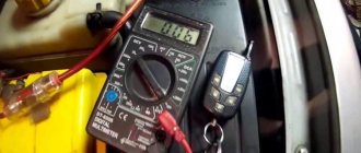
In the case when its value is in the range from 0.2 to 0.5 Ampere, the decision on the advisability of further actions is made independently. If the current exceeds the upper measurement limit (as shown in the following photo), you should stop measuring immediately and call a specialist.
6. If the leakage current in the car is greater than the critical value, begin to search for the specific cause and its source.
An assistant is needed for this. He will sequentially remove and insert fuses into their original places. At this time, the “operator” of the multimeter must monitor changes in the device readings.
If, with the fuse removed, the readings do not change significantly (by more than 5%), it means that practically no leakage current flows through this fuse.
It is more correct to start turning off - turning on with powerful fuses designed for high currents. This can speed up the search process. Usually along a chain of large rated fuses there are several smaller fuses.
If, for example, when dismantling the fuse responsible for the body control unit, the leakage current has decreased significantly, it is necessary to move on to monitoring small fuses responsible for lighting equipment, wipers, washer and other elements of body equipment.
Video - finding a current leak in a car:
It is best to go through all the fuses using this method. Car alarm fuses are usually not installed in standard places; they can “hang” next to the main alarm unit.
Some auto electricians use a sophisticated testing method. It does not require an assistant.
7. Complicated method. In this case, the positive terminal of the battery is connected back. The fuses are pulled out sequentially. The multimeter probes are installed in the connectors of the removed fuse, monitoring the current in a specific circuit. This method is more labor-intensive, but accurate.
8. Having deciphered all the circuits through which current flows from the fuse layout diagram, proceed to establish the specific cause of the leak in these circuits. To do this, you need experience working with car electrical circuits. The most common reasons:
- wiring short;
- relay sticking;
- failure of electronic components.
9. To temporarily eliminate the problem of current leakage, you can not replace the fuse through which the leakage occurs. For example, if the cause of the leak is a malfunction of the car radio, you can turn off the corresponding fuse while parked.
What is a multimeter
First, let's take a look at the front panel of a digital multimeter. It has the following symbols:
- switch-off mark – OFF;
- alternating voltage sign – ACV;
- constant voltage - DCV;
- DC icon - DCA;
- nominal resistance – Q.
All these elements are visible in more detail in the picture below:
Attention should be paid to three connectors intended for connecting probes. For proper operation of the device, it is very important not to confuse the connection of these elements with the tester. The marking COM indicates the output for the black wire. Intended for several types of measurements, red is connected via “MΩmA”. But this is only when testing current up to 200 mA. For higher parameters, the “10 ADC” connector is used. Follow the correct procedure to avoid blowing the fuse.
Outdated versions used an analogue or pointer design. Now such samples have practically disappeared due to too significant errors in measurements and an inconvenient format for working with the scoreboard.
For those who still have preserved such a rarity, we recommend watching the video:
Measuring current with a multimeter and other network parameters with modern digital testers is much more convenient and accurate. Let's look at the sequence of actions to identify the causes of the leak.
How does it proceed
- Option one. The housing or frame of an electrical installation (refrigerator, system unit, washing machine, etc.) touches a metal conductor in contact with the ground. This could be a heating radiator, a damp concrete floor in an apartment, or another electrical installation connected to ground. At the point of contact, the circuit closes and the same leakage current occurs. What is the danger? Local heating of the contact point may cause a fire. If the contact is reliable, the current will increase to the threshold of the protection device (input circuit breaker on the power panel). With a weak touch, sparking and the same local heating will be observed. Most often, this leads to melting and further damage to the supply wires. In addition, this phenomenon provokes electromagnetic interference.
- Option two. The electrical installation housing does not have contact with grounded objects and is not itself grounded. When a person touches the external panels, a load occurs (the human body is a conductor), and an electric current flows through the body. Since the resistance in this case is high, the current strength is insufficient to trip the circuit breakers. But harm to health, even death, can be caused. It is unacceptable to rely on the user to wear shoes with rubber soles. It’s the same as thinking that a linoleum-covered floor protects you from electric shock. Moreover, when the washing machine is operating, the owner’s hands are most often wet, which reduces the resistance of the skin. And if in the first case a properly selected circuit breaker is sufficient, the second option requires more advanced measures. For example, the inclusion of an RCD in the power circuit, which reacts to a small leakage current rating, provokes the operation of a circuit breaker.
Important: Even if you are confident that electrical installations and current-carrying lines are in good condition, periodic checking of current leakage is mandatory in each room. How can you determine whether there is a problem or not? To measure the leakage current, they usually call a team of master electricians who search for problematic installations using the device
At industrial facilities, this procedure is mandatory, as well as when commissioning housing stock. At large enterprises in big cities, such as Moscow, there are even staff departments of specialists on this issue
How can you determine whether there is a problem or not? To measure the leakage current, they usually call a team of master electricians who search for problematic installations using the device. At industrial facilities, this procedure is mandatory, as well as when commissioning housing stock. At large enterprises in big cities, such as Moscow, there are even full-time departments of specialists on this issue.
How can you independently check the leakage current in an apartment or residential building? The sensation of tingling electric current when you touch the body of the washing machine with a wet hand is a dubious and dangerous diagnosis.
Prevention
In addition to the obvious danger of electric shock or fire, there are smaller troubles:
- malfunctions of music, television equipment, computer equipment;
- interference on radios, mobile and radio telephones, sound amplifiers;
- a banal failure of expensive equipment: no device is designed for the flow of electric current through the housing;
- increased energy consumption, even when household appliances are turned off.
How to deal with this?
Radical method: completely unplug all electrical appliances that you are not currently using. However, this is not a solution to the problem; sooner or later trouble will happen.
The correct solution is to localize and eliminate the current leak in the house. Do I need a special expensive device for this? It’s not necessary; you can look for the problem using available methods.
Important! All electrical appliances, especially those made in a metal casing, must be grounded!
Then any insulation failure or other malfunction that leads to the appearance of a dangerous potential on the housing will trigger the circuit breakers.
Not less important! Grounding without properly selected circuit breakers is as useless as an airbag without seat belts in a car. Only comprehensive protection will save your life and equipment.
Of course, grounding must be functional and properly organized. In a private home this is not a difficult task, but in an apartment building you will have to consult the management company.
The best means of prevention is the installation of a residual current device (RCD). If a leak occurs on any electrical appliance, the RCD will be triggered constantly. This is a signal to look for a problem, and at the same time protects residents.
How to find an energy consumer?
Further search for current leakage in the car is carried out using the fuse box (usually installed under the hood near the windshield). The procedure is as follows:
- Leave the ammeter connected to the battery terminals and remove the fuse box cover.
- Alternately pulling out the fuses from their sockets, monitor the readings on the multimeter display. If the manipulation does not produce results and the current value remains the same, insert the element back into the socket and move on to the next one.
- When you notice a drop in current to normal, find out which electrical appliances are “hanging” on the circuit of the pulled fuse. Look for the “culprit” using the method of elimination, checking each consumer separately.
Example: a high-consumption circuit powers 3 pieces of equipment - a cigarette lighter, a rear window defroster and a courtesy lamp.
It is not difficult to deal with the cigarette lighter and the light bulb - you need to turn off these devices and measure the current at the relay contacts that close the heater circuit. If the readings are higher than normal, disconnect the heating element connector and try replacing the relay. Several consumers are powered directly from the battery, bypassing the fuse box. This includes the electronic engine control unit, starter and generator. If manipulations with fuse links do not bring results and the display readings have not changed, proceed to checking the electric generator:
- Disconnect the positive battery terminal.
- Unscrew the power wire from the generator and wrap the exposed end with any dielectric (you can use a rag) to avoid a short circuit.
- Connect a multimeter to the battery open circuit and check the current value. If the diode bridge in the generator fails, consumption will drop to normal.
Typically, a broken alternator diode causes a large current draw, measured in amperes. The loaded winding acts as an electromagnet, which can be easily checked using a metal key attached to the unit pulley. If the key is pulled, the electric generator is probably faulty and is wasting battery power.
In a similar way, you can measure current leakage in other directly connected circuits. Look at the electrical diagram of the car and disconnect the wires one by one, bypassing the fuse box. If for various reasons the multimeter is missing, try to solve the problem in the following ways:
- carefully inspect the inside of the car for a burning light in the glove compartment or trunk;
- try with your hand the glass with built-in electric heaters;
- check if the seats are heating up;
- Turn off the burglar alarm and stereo amplifier completely.
When faced with current leakage and battery discharge, remember what non-standard equipment you happened to install on your car in recent days. The reason probably lies in the incorrect connection of the device.
When will the RCCB (RCD) operate?
The RCCB trips when a certain level of differential current is exceeded. It turns out that the VDT does not care what the reason for the origin of the differential current to which it reacts is - the main thing is important to it (we are not talking about the type and shape of the current yet).
The operation (shutdown) level can be called the differential current setting, but correctly - the rated differential current
IΔn
(clause 5.2.3, also GOST).
From the value of the differential current IΔn and above, up to the rated maximum making and breaking capacity IΔm, the RCCB must be switched off
.
But the VDT can be switched off
, if the differential current is higher than
the rated non-breaking differential current IΔn0
, which is equal to half the breaking current. Maybe, although you don't have to.
These guys can turn off if the differential current is greater than 15 mA:
RCD RCBO and RCBO for 30 mA.
And no one will condemn them for this, since this act will be strictly within the framework of GOST IEC 61008-1-2020.
Picture on topic:
Rated non-breaking residual current
How to determine if an electrical appliance is damaged?
The classic means of measuring insulation resistance is a megohmmeter, but since such a device is quite rare in household use, for this purpose you can use the simplest and most accessible measuring instruments, such as a voltage indicator and a multimeter.
Another option is to check for current leakage with a voltage indicator. This testing method can be used if the electrical device being tested has a metal shell. If there are doubts about the serviceability and safety of using the device, the presence or absence of a leak can be checked with an indicator screwdriver designed to search for a phase in the network. To do this, it is necessary, when the consumer is switched on, to touch the tip of the indicator screwdriver to the metal body of the electrical device; if even a slight activation of the phase detector indication occurs, the consumer being tested is faulty and poses a danger. We described in more detail how to use an indicator screwdriver in a separate article.
Current leakage into the housing in a device with a metal shell can be caused not only by loss of insulation resistance. The reason for this may be a break in the jumper grounding the metal body of the product, if a grounding system is provided.
Important! During the inspection, you must be careful and avoid touching the metal body of the product and the screwdriver tip with your hands. Check with a multimeter. Checking the insulation resistance with a multimeter is carried out only on de-energized equipment
Before checking, the measuring device must be switched to resistance measurement mode at 20 MΩ. Fix the multimeter probe on the body of the product being tested, the second on one of the contact pins of the plug. The same operation must be done for the second contact pin and with the polarity of the probes replaced. On working electrical equipment, infinity should appear on the scale of the measuring device. Otherwise, the electrical equipment cannot be used; it must either be sent in for repair or disposed of. We also reviewed the operating instructions for the multimeter on the website
Checking the insulation resistance with a multimeter is carried out only on de-energized equipment. Before checking, the measuring device must be switched to resistance measurement mode at 20 MΩ. Fix the multimeter probe on the body of the product being tested, the second on one of the contact pins of the plug. The same operation must be done for the second contact pin and with the polarity of the probes replaced. On working electrical equipment, infinity should appear on the scale of the measuring device. Otherwise, the electrical equipment cannot be used; it must either be sent in for repair or disposed of. We also reviewed the operating instructions for the multimeter on the website
Check with a multimeter. Checking the insulation resistance with a multimeter is carried out only on de-energized equipment. Before checking, the measuring device must be switched to resistance measurement mode at 20 MΩ. Fix the multimeter probe on the body of the product being tested, the second on one of the contact pins of the plug. The same operation must be done for the second contact pin and with the polarity of the probes replaced. On working electrical equipment, infinity should appear on the scale of the measuring device. Otherwise, the electrical equipment cannot be used; it must either be sent in for repair or disposed of. We also reviewed the operating instructions for the multimeter on the website.
Checking with a megger. The checking procedure is the same as in the case of a multimeter. When using a megger, you must remember that when you rotate its handle, a voltage of 500 to 1000 volts is generated at the output of this device, which can irreversibly damage low-current electronic elements of the equipment.
We talked about how to use a megaohmmeter in a separate article on the website!
Measurement
According to the requirements of the GOST IEC 60335-1-2015 standard [3], the measurement of leakage currents of electrical equipment is performed during normal operation of the device under the most unfavorable conditions of its use for a period of time, which may consist of more than one operating cycle.
During testing of household electrical equipment, heating appliances are operated at 1.15 times the rated power input. Motor driven appliances and combination appliances are supplied at a voltage equal to 1.06 times the rated voltage. Three-phase appliances which, according to the installation instructions, are also suitable for single-phase supply are tested as single-phase appliances with three circuits connected in parallel. Before testing, disconnect the protective resistor and radio interference suppression filters.
The leakage current is measured using a multipole measuring network shown in Fig. 4 of the GOST R IEC 60990-2010 standard [6] (see Fig. 2 of the article “Touch Current”), between any pole of the power source and accessible metal parts connected to a metal foil having an area of at least 20 × 10 cm, which is located in contact with accessible surfaces of insulating materials. Therefore, the leakage current measured in accordance with the requirements of the GOST IEC 60335-1-2015 standard is equal to the touch current measured in accordance with the requirements of the GOST R IEC 60990-2010 standard.
For single-phase Class II instruments, the measuring circuit shown in Fig. 1 of the GOST IEC 60335-1-2015 standard [3] (Fig. 1 of this article), for devices other than class II - in Fig. 2 (Fig. 2). The leakage current is measured with a multi-position switch located in each of positions “a” and “b”.
For three-phase Class II devices, the measuring circuit shown in Fig. 3 of the GOST IEC 60335-1-2015 standard [3] (Fig. 3), for devices other than class II - in Fig. 4 (Fig. 4). The leakage current is measured with switches "a", "b" and "c" in the closed position. The measurements are then repeated with each of switches "a", "b" and "c" open in turn, while the other two switches remain closed. For devices intended to be connected only by star, the neutral is not connected.
Rice. 1. Schematic diagram for measuring leakage current at operating temperature for single-phase connection of class II devices (based on Figure 1 from GOST IEC 60335-1-2015)
The picture shows:
- C – circuit fig. 4 standards GOST R IEC 60990-2010;
- 1 – accessible part;
- 2 – inaccessible metal part;
- 3 – basic insulation;
- 4 – additional insulation;
- 5 – double insulation;
- 6 – reinforced insulation.
If the electrical appliance contains capacitors and is equipped with a single-pole switch, the measurements are repeated with the switch in the “Off” position. If the electrical appliance contains a temperature control device that operates during the test, the leakage current is measured immediately before the control device opens the circuit.
Rice. 2. Schematic diagram for measuring leakage current at operating temperature for single-phase connection of devices other than class II (based on Figure 2 from GOST IEC 60335-1-2015)
Note. For class 0I devices and class IC devices (measuring multi-port) can be replaced with a low impedance ammeter.
Rice. 3. Schematic diagram for measuring leakage current at operating temperature for three-phase connection of class II devices (based on Figure 3 from [2])
Figure 3 shows:
- C – circuit fig. 4 standards GOST R IEC 60990-2010;
- 1 – accessible part;
- 2 – inaccessible metal part;
- 3 – basic insulation;
- 4 – additional insulation;
- 5 – double insulation.
Rice.
4. Schematic diagram for measuring leakage current at operating temperature for three-phase connection of devices other than class II (based on Figure 4 from [4]) Note. For class 0I devices and class IC devices (measuring multi-port) can be replaced with a low impedance ammeter.
The leakage current is measured using a multipole measuring network, the diagram of which is shown in Fig. 10 of the GOST R IEC 60745-1-2009 standard [5], between any pole of the power supply and accessible metal parts and metal foil with an area of at least 20 × 10 cm in contact with accessible surfaces of insulating material connected together. Therefore, the leakage current measured in accordance with the requirements of the GOST R IEC 60745-1-2009 standard is equal to the touch current measured in accordance with the requirements of the IEC 60990 standard.
Three-phase instruments that are suitable for single-phase supply are tested as single-phase instruments with three sections connected in parallel. For single-phase instruments and three-phase instruments tested as single-phase instruments, the leakage current is measured with the multi-position switch shown in Fig. 3 GOST R IEC 60745-1-2009 (Fig. 5), located in each of positions “1” and “2”, and switch “S1” in the “On” position.
Rice. 5. Circuit for measuring leakage current at operating temperature for single-phase connection and three-phase instruments suitable for single-phase supply (based on Figure 5 from GOST R IEC 60745-1-2009)
Figure 5 shows:
- C – circuit fig. 10 (from GOST R IEC 60745-1-2009) for leakage current meter;
- S – power switch of the tested product;
- 1 – accessible part;
- 2 – inaccessible metal part;
- 3 – basic insulation;
- 4 – additional insulation; 5 – reinforced insulation;
- 6 – double insulation.
For three-phase instruments not suitable for single-phase supply, the leakage current is measured in accordance with Fig. 4 GOST R IEC 60745-1-2009 (Fig. 6) with switches “a”, “b” and “c” in the “On” position. For instruments intended to be connected in star only, the neutral is not connected.
If the instrument contains one or more capacitors and is provided with a single-pole switch, the measurements are repeated with the switch in the "OFF" position.
Rice. 6. Circuit for measuring leakage current at operating temperature for single-phase connection and three-phase instruments suitable for single-phase supply (based on Figure 6 from GOST R IEC 60745-1-2009)
Figure 6 shows:
- C – circuit fig. 10 (from GOST R IEC 60745-1-2009) for leakage current meter;
- 1 – accessible part;
- 2 – inaccessible metal part;
- 3 – basic insulation;
- 4 – additional insulation;
- 5 – three-phase power supply;
- 6 – double insulation.
How to use a tester (multimeter) to check current leakage on a car
Using a multimeter is the only way to detect current loss and determine its magnitude.
First, measure the voltage on the battery to exclude its discharge or malfunction, and then:
Turn off the ignition, disconnect both terminals sequentially from the battery contacts
Be careful not to touch both terminals, the positive terminal and the housing at the same time. To measure current leakage, you need to set the multimeter to constant voltage measurement mode (V 100): connect the red probe of the device to the positive terminal, and the black probe to the negative terminal. Measure the leakage current in the car with a multimeter: read the readings from the display. The normal voltage on a new battery is 12.5-12.9 volts, on a previously used one - 12.0-12.8 volts. Disconnect the device from the battery, replace the terminals, start the engine, apply a small load, for example, turning on the side lights or heated windows. Repeat measurements in operating mode
Since the generator is now turned on, the voltage should increase to 13.0-13.5 volts, sometimes up to 14.2 volts.
If the voltage does not change or changes slightly when the generator is running, the part is most likely faulty. The service center will be able to finally “diagnose” the generator.
Well, if the voltage has increased, you can continue searching for current leakage. To do this, turn off the ignition again and, without removing the terminals, measure the voltage at the battery. Repeat the measurements every 1-2 hours during the day, if during this period the voltage drops by 0.2 volts or more, there are serious leaks in the circuit. There is another way that involves:
- disconnecting the negative terminal from the battery;
- setting the multimeter to current measurement mode (A 0.1 or mA 100);
- connecting the red probe of the multimeter to the negative terminal of the battery, and the black probe to ground (housing);
- reading readings.
Finding a wiring problem
A leak in the hidden wiring of a house or apartment can cause electric shock when plastering walls or wallpapering. How to detect it without involving specialists and using special devices. There is a proven way to check for leaks in hidden wiring in a house or apartment using a transistor radio that has medium-wave and long-wave reception ranges. Before checking, you must turn off all electrical consumers. Next, you need to walk with the receiver, pre-tuned to a frequency on which there are no radio stations broadcast, in close proximity to the walls where the wiring is laid. As you approach the problem area, the receiver's speaker will begin to make a characteristic noise.