The danger of electric shock to people, damage to electrical equipment, additional load on the network and a short circuit with the possibility of fire are far from uncommon even with externally working electrical wiring. The reason for this is the thinning and loss of electrical insulating qualities of the conductor sheath. Let's look at what safety measures need to be taken in this case, what insulation resistance measurements are, how often they are carried out, why current leakage occurs and what its consequences may be, for what reasons the insulation deteriorates, what methods and instruments are used and what the instructions for taking measurements look like .
Timely checking of insulation resistance allows you to avoid an accident in the electrical network Source remkip.ru
Insulation resistance measurement - what it is, why it is carried out, frequency
The resistance of the insulating sheath of wires and cables of the electrical network characterizes the degree of protection of the outer dielectric layer from leakage or breakdown of current passing through the metal conductors. Moreover, such measurements are regularly carried out at industrial enterprises, public facilities, lighting lines, etc. The main goal is to detect current leakage and prevent serious problems.
Carrying out measurements of insulation resistance is regulated by such regulatory documents as PTEEP, POT, GOST - depending on the object/equipment and the characteristics of its power supply. The frequency of the procedure is also determined by these rules and varies from once every 6 months to 3 years. The last, longest period between inspections specifically applies to private houses. The event is officially held by representatives of Rostechnadzor or private companies with permission. The results are recorded in a special protocol.
The resistance of the insulating coating of wires is measured at least once every 3 years Source tildacdn.com
However, homeowners have much more fundamental needs for such measurements than just the requirements of the legal framework. The case concerns the safety of household members, as well as the safety of equipment, the house and adjacent objects. Thus, when a current leak occurs, the consequences may vary depending on the accompanying conditions - from frequent tripping of the RCD to a fire or electric shock to people.
Note! In order to measure the insulation resistance of electrical wiring in the house, you do not need to wait for the recommended established period - the 1st measurement every 3 years. It is necessary to pay attention to the general situation of the network. If the machine starts to operate frequently, this is the best reason to take measurements of problem areas.
What are electrical installation tests and why do they need to be carried out?
Electrical equipment testing is a set of works on diagnostics and laboratory measurements of industrial equipment and electrical networks. The main goal of the tests is to ensure reliable and uninterrupted operation of electrical equipment, protect human health and life, save money, and reduce the risk of emergency situations in the power supply system. Tests can be acceptance or preventive. Based on the test results, a technical report is drawn up.
Such documentation is required in the following cases:
- commissioning of a new facility - an apartment building, office, commercial or industrial building;
- change of owner of an object - a residential building, building or premises;
- planned capital, unscheduled or emergency repairs, changes in technological design, modernization or reconstruction of electrical equipment;
- expiration of the validity period of an existing technical report;
- receiving instructions from the inspector of Rostekhnadzor, Gospozhnadzor, Ministry of Emergency Situations.
Current leakage in new conductors and its consequences
Leakage current occurs in both old and new wiring. In the first case, the cause is the natural destruction of the shell due to the end of its service life. In the second case, there may be much more reasons.
Often the conductor shell is deformed during electrical installation work Source asutpp.ru
See also: Catalog of companies that specialize in electrical work of any complexity
The damage is of the following mechanical nature:
- During installation - when fixing with brackets, threading through corrugation, laying in a groove.
- If the insulating layer is not properly cleaned.
- At the moment of fastening in the shield, socket, distribution box.
- As a result of careless finishing work.
A decrease in the resistance of the insulating shell leads to the appearance of a phenomenon such as current leakage. As a result, electric current from the conductor begins to penetrate the electrically conductive parts of devices, structures, structures, one way or another connected to the ground. A kind of alternative electrical circuit is formed. Only, unlike the normal one that works for the home, it only consumes electricity, and also leads to instability of the former and a high risk of such serious consequences as fire or electric shock to household members.
Advice! Checking the insulation resistance of wires and cables in your home, regardless of the frequency recommendations specified in the regulatory documentation, must be carried out at least 2 times. The first time the conductors should be checked immediately after installation, the second time - after completing the interior finishing.
Electrical insulation resistance must be performed at least 2 times - after installing the wires and after finishing the walls Source klinskiy-dom.ru
Practical benefits of a technical report
The main purpose of the technical report is to provide an independent expert assessment of the safety of the electrical equipment, installations and electrical network used. This document documents the compliance of the technical characteristics of the equipment with the requirements set out in the PUE, PTEEP and others.
At a practical level, analysis of a technical report allows you to solve the following problems:
- quick inspection by the authorities of Rostekhnadzor, Rospozhnadzor and others;
- reviewing the costs of operating electrical equipment in terms of replacing wiring, switches, panels and other things;
- avoidance of penalties and shutdown of the enterprise;
- the possibility of expanding production without replacing equipment, if the power and technical characteristics of the power plant allow this.
Note! In the event of a fine or other penalty imposed by supervisory authorities, the Technical Report may be presented in court to appeal an unlawful decision, as objective and impartial evidence of the serviceability of all components of the electrical network.
Reasons for deterioration of insulation
There are the following number of reasons for the decrease in the resistance value of the insulating layer:
- Initially, poor quality of the shell material, manufacturing defects.
- Damage during electrical installation work.
- Deformation under the influence of tools and materials used for finishing.
- Under the influence of overheating, when the metal core heats up when connecting powerful devices, and the coating cracks, melts, and dries out.
- During freezing and thawing of soil masses, when the cable is laid in the ground.
- Exposure to environmental factors - sunlight, temperature changes, precipitation.
- Long-term operation.
Important! The most common cause of sheath damage is careless conductor fastening. The slightest contact with sharp edges of nail heads, screws, installation tools, as well as pulling wires through cable channels is accompanied by damage to the coating. Therefore, the frequency of measuring the insulation resistance of electrical wiring should correspond to the frequency of electrical installation work.
The inclusion of powerful electrical appliances in the network is a common cause of degradation of the insulating sheath of wires Source otoplenie-gid.ru
What is a grounding circuit?
The grounding chain consists of several connecting elements:
- conductor directly
- clamp connecting the electrode and conductor
- electrode placed in the ground
The low level of resistance of such a circuit allows current to flow into the ground, and the instantaneous response of protective relays helps to instantly isolate equipment (and people) from high voltage.
Grounding and insulation are a set of measures aimed at protecting people and equipment both at home and in the workplace. It is important to regularly check the insulation resistance to ensure a high level of protection is provided. In order for this level to be guaranteed, all values of the ground circuit elements must tend to zero, but such resistance values are rarely encountered during testing.
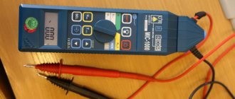
Methods and instruments for testing
In order to measure the resistance value of the conductor coating, a specialized device is used - a megohmmeter. For home electrical networks, the nominal value of which ranges from 220-380 V, the procedure is carried out within 500 V. In this case, the minimum value of the measured indicator should not be less than 500 kOhm, or 0.5 MOhm. Otherwise, this will mean that the insulation is broken and the conductor in this part of the circuit needs to be replaced.
The resistance of the electrical network in a private house is measured either between current-carrying conductors, or between each specific wire and the ground loop. The following measurement options are available:
- Phase – working zero.
- Phase – ground loop (PE).
- Phase – phase.
- The working zero is the ground loop (PE).
Such a universal device as a multimeter also has the ability to measure resistance. However, the function is intended to take readings of the electrical circuit itself, and not of the insulating sheath of the conductor. Therefore, in the case under consideration it is not applicable.
Assessment of the condition of existing electrical equipment
Assessment of the condition of electrical equipment based on the results of inspections, measurements and tests
An assessment of the condition of electrical equipment and its readiness to be put into operation is made after comparing the results of various measurements and tests with the permissible ones regulated by special standards. The main regulatory documents are the “Norms for Testing Electrical Equipment” (hereinafter referred to as the Norms) and the “Rules for the Construction of Electrical Installations” (PUE).
The conclusion about the possibility of putting equipment into operation is made based on the totality of the results of acceptance tests, since it is often difficult, especially in assessing the state of insulation of electrical machines, power transformers and the need to dry it, to find a solution based on one or even two criteria.
When assessing the condition of equipment, a widely used method is to compare the measurement results of equipment of the same type, based on the assumption that all equipment of the same type being tested cannot have the same damage. So, for example, if the magnetization characteristics of a group of measuring current transformers are equally below standard ones, and the no-load current of several voltage transformers is equally higher than permissible, then this means that there is not damage to the insulation of the windings or magnetic circuit, but the use of steel in the magnetic circuit that differs in dimensions or assortment from the one for which the typical characteristics were taken.
The results of measurements and tests are always compared with the results of previous measurements and tests for evaluation. For newly introduced equipment, these are the results of factory tests and measurements. Differences are allowed only within the limits of accuracy and differences in the measurement methods used.
The checks and tests provided for by the Standards are not always sufficient, especially when assessing the condition of non-serial equipment or a prototype. In such cases, they are produced according to a special program drawn up by the developing organization with the participation of design and operating organizations. As a rule, such programs are approved by the chief engineer of the station or power system.
The final judgment on the possibility of including the equipment in normal operation allows you to test it in action.
Testing of electrical equipment in action is carried out after complete installation and pre-commissioning work.
During testing, checks, tests and measurements are performed that cannot be made due to technological conditions when the equipment is stationary, but are necessary for a final conclusion about the suitability of the equipment and operation. Testing methods depend on the type of equipment.
Switching devices are tested in a certain cycle of switching on and off operations by supplying them with a standard operating current (standardized by the Standards) with measuring time, speed of switching on and off, the minimum operating voltage of the drive electromagnets, checking the operation of the drive at different levels of operating current voltage or air pressure from the air switches, oscillography of their various cycles and other checks and measurements regulated by the Standards.
Power transformers are tested by applying voltage to them, checking its operation “by ear”, the operation of relay protections and the tap switch.
Testing of synchronous generators is carried out according to a special program, checking the operation of all automation systems and devices, relay protections and, as a rule, ends with synchronization and its inclusion in normal operation.
Electric motors are tested by applying voltage to them, first with the clutch connecting to the driven mechanism disengaged, and then, with satisfactory results of such testing at idle, with the driven mechanism. The measured currents and behavior of the electric motor allow one to judge the quality of the installation and its readiness for operation.
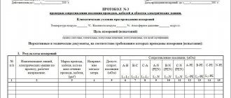
Preparation of inspection and test reports
All results of inspection, testing and testing of electrical equipment, which are carried out during the commissioning process, are documented in protocols. The protocols contain a conclusion that provides a general assessment of the condition of the equipment, all the results of measurements, inspections, tests and testing.
In some cases, instead of protocols, reports are drawn up on all inspections, tests and measurements performed with a conclusion containing an assessment of the condition of the equipment.
In order to unify technical documentation, simplify and reduce the time required for its registration, commissioning organizations are developing standard forms of protocols and reports that only require filling them out.
Instructions for taking measurements
In order to measure the sheath resistance of home wiring, you must follow the following instructions:
- Conduct a visual inspection of the network.
- Unplug all devices from the sockets, turn off the RCD and circuit breakers.
- The terminals are connected to the phase and zero of the input panel, and measurements are taken.
- Next, all groups are checked separately.
- Before moving on to measuring the next group, the charge is first removed from the ohmmeter.
When measuring the insulation resistance of home electrical wiring, the readings should tend to the infinity edge of the instrument scale. The minimum acceptable value is 0.5 MOhm. If less, it means there is a current leak and the conductor will need to be replaced.
Why is a technical report needed?
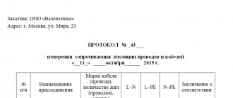
The technical report and measurement protocol are the basic reports of the electrical laboratory engineers who carried out electrical measurements and testing of the electrical equipment. Documents of the established form are drawn up by ETL and provided to the customer.
The technical report consists of:
- title page, which indicates the customer, performer, date of measurements;
- content;
- an explanatory note indicating the purposes of the measurements, the characteristics of the construction site where the measurements were taken, as well as a list of tests performed;
- programs of measurements performed, test results;
- measurement protocol (filled out on a standard form, contains information about the methods of testing and the step-by-step process of work);
- indications of identified defects and shortcomings that may affect the safe operation of the network and power plant;
- conclusions of ETL specialists on the safety or unsafety of operating the network and power supply, compliance of the equipment being tested with the requirements of the Electrical Electrical Regulations, GOST, PTEEP.
- copies of the certificate of registration of the electrical laboratory, which indicates its right to conduct electrical tests and draw appropriate conclusions.
Briefly about the main thing
The resistance of the wire's insulating sheath determines the level of protection against electric current breakdown. The frequency of parameter measurement is subject to PTEEP, POT and GOST standards, depending on operating conditions and characteristics of electrical networks. Measuring the resistance of a home network allows you to detect leakage current in time and prevent destructive consequences.
Current breakdown can occur both in old conductors - due to natural deterioration of the sheath, and in new ones - primarily due to mechanical damage during careless installation. Among the most common reasons for a decrease in insulation resistance are the following:
- Poor quality coating.
- Damage during installation.
- Destruction during wall finishing.
- Overheating under heavy network load.
- Impact of natural environmental factors.
- Long-term operation.
The frequency of measuring the insulation resistance of internal home or external networks for powering lighting systems, equipment and various installations in the local area is once every 3 years. However, for safety reasons, the procedure must be carried out every time after electrical installation work and finishing. Measurements are carried out with a megohmmeter between live wires or conductors and the ground loop according to the instructions. The reading of the device in the normal state of the insulating coating should be at least 0.5 MOhm.
Classification
Experts classify activities in this direction according to the purpose of their implementation. Types of electrical equipment testing:
1. Standard. They are carried out at the production stage. This type is initiated by the developer. The feasibility of using technologies and manufacturing methods is checked. At this stage, it is possible to make adjustments to the production cycle. 2. Controls. Initiated by the manufacturer. The goal is to check compliance with technical regulations. This is the last stage before the product is released. Other studies include testing for consumer safety. The goal is to prevent the release of obviously low-quality products onto the market. 3. Acceptance documents. They are part of the introduction of a new system into the production process. Carried out upon completion of installation. Essentially, this type is permission to start the electrical system. 4. Operational. They are carried out for preventive purposes. 5. Special. This is a special kind. Needed for research purposes only.
Why the ground level cannot be zero
On the practical side, the resistance of the grounding element (metal rod) includes several components:
- resistance of the metal shell of the electrode and resistance at the junction of the conductor with the ground rod
- resistance at the junction of the rod with the ground
- resistance of the earth's surface to the current entering it - this is called earth resistance
Ground resistance is the most important part of grounding. The soil layer closest to the electrode has the smallest surface and the highest resistance. If the layers of earth are removed from the rod, then the resistance decreases.