Alternating current is the main source of domestic and industrial power supply. When voltage is applied to consumers, resistance arises. The article will give a detailed explanation of what active resistance is in an AC circuit.
Additionally, a formula for calculating this value will be given, the varieties, conditions for an ideal chain and the main factors influencing the increase in these values will be described.
Alternating current
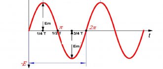
In order to understand what active resistance is, it is necessary to understand the phenomenon of alternating current itself. An alternating current is a type of current that continuously changes the direction of its flow. During flow, the alternating current potentials are constantly changing. This occurs due to the operation of the generator, or more precisely due to the interaction of the magnetic field with the copper winding. The movement can be clearly seen using an oscilloscope. Its shape resembles a sinusoid.
The role of alternating current is difficult to overestimate. Its main advantage is the ease of transmission from source to consumer, the ability to lower or increase the voltage using transformers. Also, alternating electric currents can be delivered to the consumer at much lower cost.
Triangle of resistances
A circuit connected to alternating current has an impedance, which can be defined as the sum of the squares of the reactive and active resistance.
If you depict this expression as a graph, you get a resistance triangle. It is formed if you calculate a series circuit of all three types of resistance.
From this triangular graph you can see that the legs represent the active and reactance, and the hypotenuse is the total resistance.
Resistance
Resistance is the ability of a conductor to slow down the passage of charged particles through its structure. This ability is affected by the material of the conductor, its thickness and length. The unit of electrical resistance is 1 ohm.
The calculation is made by passing a voltage of one volt through the conductor and a current equal to one ampere. In electrical diagrams, this parameter is indicated by the letter “R”.
Active resistance
Alternating current is delivered to the consumer for the purpose of converting it into other types of energy, for example, heat and light. In household networks, the use of single-phase alternating current predominates. When connecting a consumer, active resistance is created.
A simple AC circuit with active resistance includes a current generator and an ideal resistor. In this case, the necessary conditions for an ideal circuit must be met:
- Active resistance should not be equal to zero, a prerequisite.
- The capacitance and inductance of the circuit must be zero.
Also, for ideal active resistance the following conditions must be met:
- Ohm's law is observed for the instantaneous, rms and amplitude parameters of the circuit.
- The value is completely independent of amplitude fluctuations.
- There is no phase shift between current and voltage.
- An element under voltage releases a share of thermal energy, that is, it heats up.
All these conditions allow electrical devices to operate within precisely defined parameters with maximum efficiency. Any change may be caused by a lack of a reliable contact connection or a malfunction of the consumer itself.
In order to calculate the value of active resistance in a circuit, it is necessary to know the value of voltage and current. The formula used for calculation is: R=U/I. The formula consists of the following values:
- “R” - resistance, Ohm;
- “U” - voltage value, volts;
- “I” is the current value, ampere.
Then you can do a simple calculation. The consumer is an electric oven connected to a single-phase alternating current circuit:
- Circuit voltage is 240 volts.
- When measuring the current, a value of 4 amperes was obtained.
- R= 240/4=60 Ohm.
The calculated resistance value is not the final value. It is influenced primarily by the cross-section of the wires included in the circuit and the interaction pattern between the circuits of capacitive and semiconductor elements.
The active value of the circuit also causes a permanent loss of the original electrical energy, and also leads to a decrease in power.
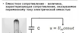
Circuit with capacitive reactance.
Let us determine the nature of the alternating current “ I
"in a circuit with a capacitor to which an alternating voltage is applied
U = U m sin t
.
Instantaneous charge values " q"
on the capacitor plates
q = cU = cU m sin
t.
Let's differentiate
where I m =
cU m
.
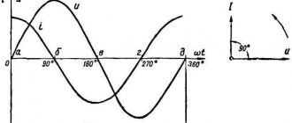
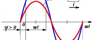
This equation shows that the current in the circuit, like voltage, has a sinusoidal character (see figure), and advances the voltage in phase by an angle. Comparing the maximum current value I m = cU m
with the formula of Ohm’s law, we see that in a circuit with a capacitance the value of resistance has a value, which is denoted by
X c .
The quantity is called the capacitance of the circuit and is measured in Ohms, if
c
- in Farads and
- in Hertz.
The physical meaning of capacitance can be explained as follows: the current “ I
” in the capacitor circuit is proportional to the charge “
q
” and the frequency “
” of the change in the processes of charging and discharging the capacitor.
The charge “ q
” for a given applied voltage “
U
” is proportional to the capacitance “
c
” of the capacitor, and
= 2
.
Therefore, the current “ I
” in the circuit is proportional to the product “
c
”, which, therefore, has the value of the conductivity of the circuit. The inverse value, that is, has the value of the circuit resistance. In a circuit containing capacitance and active resistance, the phase shift angle of the current will be smaller and, depending on the relationship between them, can have values from 0 to 90. In a purely capacitive resistance, there is no energy loss occurs, which is why it is called reactive.
34. Impedance of an alternating current circuit. Impedance. .
Consider
a circuit consisting of the last connected resistor R, inductor L
and capacitor
C.
If an alternating current is applied to it.
voltage, then the current in the circuit will change according to the law: , where is the phase difference between voltage and current strength. Such a chain named after both active and reactive resistance. => its resistance is called. impedance and denoted by Z. Impedance
is equal to the amplitude ratio. values changeover. for example, at the ends of the chain to amplitudes. The value of the current in it:
Elements(R,L, C)
complete AC circuit
current in Fig. connected in series.
=> the flow through them is the same.
current, and for example the warehouse from the voltage to the department. sections of the circuit: For adding voltage using. track. graphic reception , all
are plotted The magnitude and direction of the vector give the amplitude of the voltage in the network and the phase angle between the current and voltage. From Fig. according to Comrade Pythagoras we have: Substituting the expressions for these amplitudes from and teaches. Ohm's law, we find: Next is the floor. value for determining impedance:
Active capacitance
In a simple circuit, the magnitude of the active value also depends on the active capacitance. For ideal capacitance, there must be a capacitor in the circuit under alternating voltage. The ideal capacitor is designated by the letter "C".
To obtain an ideal circuit with active capacitance, the following conditions must be met:
- Active inductance and resistance must be 0.
- The capacitance of the capacitor itself in the circuit must be greater than 0.
Under these conditions, the electrical circuit acquires the following features:
- Ohm's law is observed without the slightest deviation.
- There is a capacitance "X" for alternating current.
- A nonlinear decrease in capacitance is observed with increasing oscillation frequency.
- There is a phase shift of up to 90 degrees between voltage and current.
- Circuit capacity is not constant. The reason lies in the periodic accumulation and release of energy.
An alternating current circuit with active capacitance can be supplemented with inductance. To create inductance, an inductor is connected to the circuit. The coil also adds its share of resistance to the overall circuit. With this connection, inductive reactance appears in the circuit. Both elements: the coil and the capacitor are not final consumers of energy. These elements are not under constant voltage; their work is based on the accumulation and release of current into the circuit.
Capacitor reactance
As we have seen from past experience, as frequency increases, current increases! By the way, the resistor did not grow. That is, in this case it turns out from Ohm’s law that the resistance of the capacitor depends on the frequency! Yes, that's all true. But it is called not just resistance, but reactance and is calculated by the formula:
Where
Xc - capacitor reactance, Ohm
P is constant and approximately equal to 3.14
F—frequency, Hz
C is the capacitance of the capacitor, Farad
Power
In the presence of active resistance, the power of this circuit is significantly reduced. This value depends on the rate of voltage reduction and electrical energy conversion. In the electrical diagram, power is designated by the letter “P”.
In order to achieve a minimal reduction in the average and instantaneous powers that are formed at the moment of the appearance of active resistance, voltage reduction and energy conversion, it is necessary that the simplest circuits consist of ideal elements with high electrical conductivity.
Addiction
The amount of active resistance largely depends on the diameter of the conductors. When high-frequency currents are applied, the resistance of the conductor can be reduced only if its surface layer is much thinner than the main one. In order to achieve an ideal cross-section, this layer must consist of a material with very high conductivity, such as gold or silver. This effect occurs due to the interaction of voltage and the magnetic field formed by it. The field strongly influences the current flowing through the conductor and pushes it to the surface layer. Thus, closer to the surface of the conductor, the conductivity decreases and becomes critically small in its upper layer.
The following effects are also present: leakage losses and dielectric losses. Both effects are associated with the presence of a capacitor in the circuit. Dielectric losses occur due to an increase in the temperature of the dielectric inside the capacitor. Leakage loss occurs due to the breakdown fraction of the capacitor insulator.
Hysteresis. This is also a type of AC energy loss. This loss occurs when a magnetic field forms around metal objects. Electromagnetic influence leads to heating of the metal, which means energy conversion.
The last leakage factor is radio emission. Radio waves appear due to a strong magnetic field and its interaction with the metals of the circuit. For suppression, especially in radio equipment, screens are used that absorb part of the field and repel the rest.
Solving this equation for f, we find
(3.40)
At voltage resonance, the source frequency is equal to the natural frequency of the circuit.
Expression (3.40) is Thomson’s formula, which determines the dependence of the natural frequency of oscillations of the circuit
, from parameters L
and
S.
_ It should be remembered that if the circuit capacitor is charged from a direct current source and then shorted to an inductive coil, then an alternating current of frequency will appear in the circuit
. Due to losses, oscillations in the circuit will attenuate, and the attenuation time depends on the magnitude of the losses.
Rice. 55
The voltage resonance corresponds to the vector diagram shown in Fig. 55. Based on this diagram and Ohm’s law for a circuit with r ,
L
and
C
, we formulate the signs of voltage resonance:
a) resistance of the entire circuit
minimal and purely active;
b) the circuit current is in phase with the source voltage and reaches its maximum value;
Rice. 56 Fig. 57
c) the voltage on the inductive coil is equal to the voltage on the capacitor and each individually can be many times higher than the voltage at the circuit terminals.
Physically, this is explained by the fact that the source voltage at resonance only goes to cover losses in the circuit. The voltage across the inductance and capacitance is determined by the energy accumulated in them, the magnitude of which is greater, the lower the losses in the circuit.
Quantitatively, this phenomenon is characterized by the quality factor of the circuit Q
,
which is the ratio of the voltage across the coil or capacitance to the voltage at the terminals of the circuit at resonance;
. (3.41)
At resonance
Magnitude
is called the characteristic impedance of the circuit. Thus,
(3.42)
The ability of an oscillatory circuit to release currents of resonant frequencies and attenuate currents of other frequencies is characterized by a resonant curve (Fig. 56).
The resonance curve shows the dependence of the effective value of the current in the circuit on the source frequency at a constant natural frequency of the circuit.
This dependence is determined by Ohm's law for a chain with r , L
and
S.
_
Indeed, I = U z
, where
(3.43)
In Fig. Figure 57 shows the dependence of reactance
on the source frequency. Analysis of this graph and expression (3.43) shows that at low and high frequencies the reactance is high and the current in the circuit is small. At frequencies close to
The reactance is low and the loop current is high. Moreover, the higher the quality factor of the circuit Q
, the sharper the resonant curve of the circuit.
Metering
Resistance measurement is carried out in the following ways:
- Voltmeter and ammeter. Using these devices, current and voltage values are measured, and then a calculation is made using the formula described above.
- Logometer. This is a device for measuring resistance under high voltage and high frequency. Its main advantage is the strong elimination of dependencies and errors.
- Ohmmeter. The device is used for signal amplifier type measurements only. When using an ohmmeter, a high error is taken into account, which can reach 5%. Conventional electronic ohmmeters are not suitable for measuring active resistance.
Course of lectures on physics Electrical engineering
Circuit with active resistance and capacitance
1. Vector diagram of current and voltage. In § 11.4 a circuit with a capacitance (ideal capacitor) is considered. In reality, any capacitor has losses, i.e., active power P. Therefore, a real capacitor can be represented by a circuit of a series connection of active resistance r and capacitive resistance xc (Fig. 12.5). Resistance r is determined by the loss power: r = P/I2. The voltage of the circuit and at any time consists of two terms: u=ua+uc. The active voltage ua is in phase with the current in circuit i, and the capacitive voltage uC is 90° behind the current in phase. Effective values of voltage components: Ua = Ir, UC = IxC = I/(C). To determine the effective value of voltage U, we will construct a vector diagram. Let's start constructing the diagram (Fig. 12.6, a) with the current vector I, putting it horizontally.
The vector of the active voltage drop Ua will be set aside in the direction of the current vector I, and the vector of the capacitive voltage drop Uc will be rotated relative to the current vector by 90° clockwise. Let's add the voltage vectors Ua and Uc, we get the voltage vector U. The voltage vectors Ua, Uc and U form a right triangle. From the vector diagram it can be seen that the voltage at the circuit terminals lags in phase with the current by an angle φ. The absolute value of this angle can be determined from the expression cosф = Ua/U.
2. Triangles of resistance and power. Let us reduce all sides of the stress triangle by I times. As a result, we obtain a triangle of resistance (Fig. 12.6, b). From this triangle it follows that the total resistance of the circuit in question
This means the current
The resulting expression is Ohm's law. By increasing the sides of the voltage triangle (Fig. 12.6, a) by I times, we obtain a similar power triangle (Fig. 12.6, c). Circuit power: active P = UaI = I2r = UI cos f, reactive QC == UCI = I2xC = UIsin f, total S = UI =.
Circuit with active resistance, inductance and capacitance
1. Vector diagram of current and voltage. If a sinusoidal current i=Imsint flows in an unbranched circuit with active resistance r, inductance L and capacitance C (Fig. 12.7), then the instantaneous value of the voltage applied to the circuit u = ua + uL+uc. The voltage across the active resistance ia is in phase with the current in circuit i, the voltage across the inductance uL leads the current by 90°, and the voltage across the capacitance c lags the current by 90°. Effective voltage values in circuit sections: Ua=Ir; UL = IxL; Uc=Ixc. The effective value of the voltage at the circuit terminals is obtained by the vector addition method: U = Ua+UL+Uc. Let's construct a vector diagram of current and voltage. First, let's plot the current vector I (Fig. 12.8a). The voltage drop vector in the active resistance Ua is compatible with the current vector I, the inductive drop vector UL is set up at an angle of 90°, and the capacitive voltage drop vector Uc is set down at an angle of 90° to the current vector I. By adding up the voltage vectors Ua, Ul and UC , we obtain the voltage vector U applied to the entire circuit. The vector diagram is constructed for the case when xL>xC and the circuit is active-inductive in nature. Under this condition, UL>Uc, and the voltage U leads the current I in phase by an angle φ. If xc>xl, to Uc>Ul and the circuit has an active-capacitive character. In this case, the voltage U (Fig. 12.9) lags in phase from the current I by an angle f. If the reactances are equal (xl=xc) Ul = Uc (Fig. 12.10). In this case, the voltage U is in phase with the current I (ph = 0) and the circuit is active. This mode in the circuit under consideration is called voltage resonance.
2. Triangles of resistance and power. Consider the stress triangle in Fig. 12.8, i. One leg of this triangle expresses the active voltage Ua, the other - the reactive voltage of the circuit UL-UC, and the hypothesis - the total voltage U. Dividing the sides of the voltage triangle by the current I, we obtain a resistance triangle (see Fig. 12.8,6), from which it follows that total circuit resistance z =. Therefore, the current in the circuit
If all sides of the voltage triangle (see Fig. 12.8, a) are multiplied by the current I, we obtain a power triangle (see Fig. 12.8, c). Power: active P = UaI = I2g = UIsos f,
where cos f = Ua/U = r/z; reactive Q = (UL - UC)I = I2·(xL - xc) = UIsin f; full S=UI=.
General case of a straight chain
1. Vector diagram of current and voltage. In Fig. Figure 12.12 shows a diagram of an unbranched circuit, sections of which have active and reactive resistance. The vector diagram (Fig. 12.13, a) shows the vectors of active voltages Ua1, Ua2, Ua3, in phase with the current, inductive - UL1 and UL2, leading the current in phase by 90°, and capacitive - UC1 and UC2, lagging the current 90° out of phase. The sum of all voltage vectors is equal to the voltage vector U at the circuit terminals. In the vector diagram (Fig. 12.14), the voltage vectors are constructed in the same sequence in which the corresponding circuit elements are connected.
2. Triangles of resistance and power. Consider the vector diagram in Fig. 12.13, a. The first leg of the resulting voltage triangle is equal to the arithmetic sum of active voltages (Ua1+Ua2+Ua3), the second leg is equal to the algebraic sum of reactive voltages (UL1+Vl2 - UC1 - UC2), and the hypotenuse is the voltage U at the circuit terminals. Reducing all sides of this triangle by I times, we obtain a triangle of resistance (Fig. 12.13, b), from which it follows that the total resistance of the circuit is z =. In general
Circuit current
By increasing each side of the voltage triangle by I times, we obtain a power triangle (Fig. 12.13, c). Circuit power: active P = I2(g1 + g2 + g3) = UI cos f, where cos f = (g1 + g2 + g3)/z or cos f=∑r/z; reactive Q = I2(xL1 + xL2 - xC1 - xC2) = UIsin f, where sin f = (xL1 + xL2 - xL3 - xC2)/z or sin f = (∑xL -∑xC)/z; full S= UI = .