In order for electrical equipment to function reliably, the insulation of wires and cables must meet safety requirements. This can be verified through regular checks, during which the insulation resistance is measured. This procedure must be carried out in accordance with current rules and requirements.
How is the check carried out?
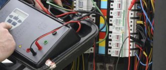
Insulation resistance measurements are in most cases carried out for the purpose of checking connecting wires and cables. If they are exposed to various influences, it is especially important to be confident that the insulation resistance meets safety requirements.
The measurement is carried out based on Ohm's law. In this case, a certain voltage is applied to the insulation, and then the current flowing through it is measured. To calculate the resistance, the formula of Ohm's law is used: Riz = U/I.
Insulation resistance measurements are performed not only to monitor the safety of the electrical network, but also during regular maintenance. Measurements of the insulation resistance of electrical wiring elements are necessary in cases where the insulation remains intact. If it is missing or there are wire cuts or other damage in certain places, then there is no point in taking measurements at this moment. First you need to repair the wire or replace it with a working one.
Safety in Insulation Testing
Before testing
A. To ensure that the test voltage is not applied to other equipment having an electrical connection to the circuit under test, the test must be performed on a disconnected, non-conducting installation.
B. Make sure the circuit is discharged. It can be discharged by short-circuiting the terminals of the equipment and/or shorting them to ground for a certain time (see discharge time).
C. If the equipment being tested is in a flammable or explosive environment, special protection is required because if the insulation is damaged, sparks may occur when the insulation is discharged (before and after testing) and during testing.
D. Due to the presence of DC voltage, which can be quite high, it is recommended that access by other personnel be restricted and personal protective equipment (such as safety gloves) suitable for working on electrical equipment be worn.
E. Use only connecting cables that are suitable for the test being performed; Make sure the cables are in good condition. At best, unsuitable cables will lead to measurement errors, but more importantly, they can be dangerous.
After testing
At the end of the test, the insulation will have accumulated significant energy which must be released before any other operations can be carried out. A simple safety rule is to allow the equipment to discharge for five times the charging time (last test time). To discharge the equipment, you can short-circuit its terminals and/or connect them to ground. All megohmmeters manufactured by Chauvin Arnoux are equipped with built-in discharge circuits that automatically ensure the required safety.
Possible causes of insulation failure
Modern industry pays serious attention to the quality of insulation of wires and cables. But despite this, from time to time problems arise with it and as a result there is a need to check the resistance. Most often, control is needed if the following factors are present:
- The wire is exposed to direct sunlight. This has a destructive effect on some types of insulating materials.
- There is prolonged exposure to high voltage.
- Temperature effects are observed.
- There are mechanical damages.
- Climatic features of a particular area. This may, for example, occur in cases where it is hot or severely cold.
Timely detection of insulation problems will allow you to avoid such dangerous consequences as a short circuit or the impact of current on a person during a breakdown.
Standards
As a result of the measurements, the actual value of the wire insulation resistance is obtained. It must be compared with standard data. To understand which document needs to be used in a particular case, you need to know what standards exist. It should be taken into account that the limit values provided by them may vary significantly. There are insulation resistance standards for:
- Power or signal cables used in various environments.
- Power electrical installations intended for industrial use.
- Household appliances equipped with a power cord.
Checking the electrical insulation resistance depends on the voltage present in the electrical network. In this case, it is necessary to take into account what model of equipment is used. Before checking, you should read the relevant documents, which indicate the standards for the insulation resistance of a wire or cable. The following is a list of the most common situations for which the permissible insulation resistance is specified:
- When using electric stoves, the insulation resistance is at least 1 MOhm.
- If the cable is laid in an area where climatic conditions can be considered normal, the minimum insulation resistance is 0.5 MOhm.
- For insulation of electrical equipment consuming voltages up to 1000 V, the maximum resistance is 1 MOhm.
- If the supply voltage of the electrical device is in the range of 100–380 V, then the limitation is 0.5 MOhm.
- In cases where the supply voltage does not exceed 50 V, the insulation resistance must be at least 0.3 MOhm.
- For cables and wires used in switchboard installations, the insulation resistance standard is 1 MOhm.
Results of work on insulation resistance measurements
Periodic electrical resistance measurements make it possible to timely assess the condition of the insulating shell and, if necessary, take measures to partially replace the wiring, which, in turn, eliminate equipment breakdowns and the possibility of a fire in the room. Verification is also required for supervisory authorities. For example, Rostekhnadzor, in the absence of a technical report and protocols with measurement results, imposes liability on the enterprise in accordance with Article 9.11 of the Code of Administrative Offenses of the Russian Federation. In addition, inspectors of the State Housing Inspectorate may require protocols of measurement results.
You should know that protocols drawn up by an electrical measuring laboratory with its own certificate of registration in Rostekhnadzor, that is, such as “MOSENERGOTEST”, are considered legally significant.
After the electrical laboratory specialists carry out resistance measurements and document all the results in the required manner, a MOSENERGOTEST employee will present the electrical laboratory’s technical report to the customer. It will include not only protocols with the results of testing the resistance of the insulating sheath of cables and wires, but also a defect sheet with comments and recommendations for eliminating defects, as well as a copy of the laboratory’s registration certificate.
If you still have questions about the work of the MOSENERGOTEST laboratory, write to us in the special feedback form on the website or call, or contact us via email. It is advisable that you voice your requirements immediately when contacting our company - this will allow us to estimate the approximate scope of work and provide you with an estimate for their implementation.
What measuring instruments can be used
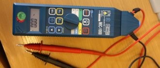
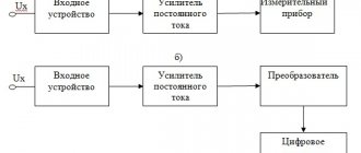
At first glance, it might seem that it would be logical to use a multimeter for this purpose. However, in most cases, the current that passes through the wiring is so small that this meter cannot accurately measure it. In such cases, it is convenient to use a megohmmeter, with which you can measure voltage and electric current. These devices can be analog or digital. Based on Ohm's law, the resistance value is determined from the data obtained.
The operating principle of the device can be explained using the example of an electromechanical version of a megohmmeter.
A hand generator (a) is used to supply current. In fact, we are talking about a handle that needs to be turned to generate energy. In this case, it is necessary that the rotation speed be at least two revolutions per second. An analog ammeter (b) is connected to the arrow of the device.
The instrument scale (c) is graduated to indicate the resistance value. The circuit uses several resistors (d). How many there are depends on the model of the device. There is a measurement scale switch (e). In this case, you can measure resistance in Ohms or MegaOhms. There are input terminals (f) to which wires are connected.
One of the advantages of such a device is that it does not require additional power, since the current obtained using a hand-held generator is used for measurements. However, when using it, it is necessary to take into account its inherent disadvantages:
- To ensure the required measurement accuracy, the device must remain stationary. However, this is difficult to achieve when rotating the handle.
- Accuracy is affected by how evenly the handle is rotated. It is necessary to ensure a constant voltage supply during measurement. Compliance with this condition is not always possible.
- It is difficult to measure insulation resistance with such a device alone. Therefore, two people usually work with it: one person turns the handle, the second directly checks the insulation resistance of the cable or other equipment.
The device uses a nonlinear scale, which negatively affects the accuracy of measurements. In subsequent models, manufacturers moved from turning a knob to generate current to using a power source. This helped get rid of most of the shortcomings of the electromechanical version of the device.
Most modern megohmmeters are digital. Microcircuits are actively used in their designs. The use of modern microprocessors and other microcircuits allows for relatively high measurement accuracy. When working with digital devices, it is enough to set the initial data and select the desired operating mode. Their advantages are compactness and great functionality.
Test methods and interpretation of results
Short-term or spot measurement
This is the simplest method. It involves applying test voltage for a short time (30 or 60 seconds) and recording the insulation resistance value at this moment. As stated above, this direct measurement of insulation resistance is significantly influenced by temperature and humidity, so the measurement should be standardized at a reference temperature and the humidity level should be recorded for comparison with previous measurements. Using this method, you can analyze the quality of the insulation by comparing the current measured value with the results of several previous tests. Over time, this will provide more reliable information about the insulation performance of the installation or equipment being tested compared to a single test.
If the measurement conditions remain identical (same test voltage, same measurement time, etc.), then with periodic measurements, a clear assessment of the insulation condition can be obtained by monitoring and interpreting any changes. After recording the absolute value, it is necessary to analyze the change over time. Thus, a measurement showing a relatively low insulation value that is nonetheless stable over time should theoretically be less of a concern than a significant decrease in insulation resistance over time, even if the insulation resistance is higher than the recommended minimum value. In general, any sudden drop in insulation resistance indicates a problem that needs to be investigated.
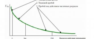
The graph below shows an example of insulation resistance readings for an electric motor.
At point A, the insulation resistance decreases due to aging and dust accumulation.
A sharp drop at point B indicates insulation failure.
At point C, the fault has been cleared (the motor winding has been rewound) and the insulation resistance has returned to a higher value that remains stable over time, indicating good insulation condition.
Test methods based on the influence of test voltage application time (PI and DAR)
These methods involve sequentially measuring insulation resistance values at specified times. They have the advantage of not being particularly affected by temperature, so they can be used without correction of the results, unless the test equipment is exposed to significant temperature fluctuations during the test.
These methods are ideal for preventive maintenance of rotating machines and for insulation monitoring.
If the insulating material is in good condition, the leakage current or conduction current will be low, and the initial measurement will be greatly influenced by the capacitance charging and dielectric absorption currents. As the test voltage is applied, the measured insulation resistance value increases over time as these interference currents decrease. The stabilization time required to measure insulation in good condition depends on the type of insulating material.
If the insulating material is in poor condition (damaged, dirty and wet), the leakage current will be constant and very high, often exceeding the capacitance charging and dielectric absorption currents. In such cases, the insulation resistance measurement very quickly becomes constant and stabilizes at a high voltage value.
Studying the change in the insulation resistance value depending on the time of application of the test voltage makes it possible to assess the quality of the insulation. This method allows conclusions to be drawn even if no insulation measurement log is kept. However, it is recommended that the results of periodic measurements performed in the context of a preventive maintenance program be recorded.
Polarization Index (PI)
Using this method, two readings are taken at 1 minute and 10 minutes, respectively. The ratio (without dimensions) of the 10-minute insulation resistance value to the 1-minute value is called the polarization index (PI). This indicator can be used to assess the quality of insulation.
The polarization index measurement method is ideal for testing solid insulation circuits. This method is not recommended for use on equipment such as oil-immersed transformers as it produces poor results even if the insulation is in good condition.
IEEE Recommendation 43-2000, Recommended Test Methods for Insulation Resistance of Rotating Machines, specifies a minimum polarization index (PI) value of 2.0 for AC and DC rotating machines in temperature classes B, F, and H. In general, a PI value greater than 4 is a sign of excellent insulation, while a value below 2 indicates a potential problem.
PI = R (10-minute insulation measurement) / R (1-minute insulation measurement)
The results are interpreted as follows:
| PI value (norm) | Insulation state |
| Problematic | |
| From 2 to 4 | good |
| > 4 | Excellent |
Dielectric Absorption Rate (DAR)
For installations or equipment containing insulating materials in which the absorption current decreases quickly, a measurement at 30 seconds and 60 seconds may be sufficient to assess the condition of the insulation. The DAR coefficient is determined as follows:
DAR = R (60 second insulation measurement) / R (30 second insulation measurement)
The results are interpreted as follows:
| DAR value (norm) | Insulation state |
| Unsatisfactory | |
| Normal | |
| >1,6 | Excellent |
Method based on the effect of changing test voltage (step voltage testing)
The presence of contamination (dust, dirt, etc.) or moisture on the insulation surface is usually clearly detected by time-dependent resistance measurements (PI, DAR, etc.). However, this type of testing, conducted using a low voltage relative to the dielectric voltage of the insulating material being tested, can sometimes miss signs of insulation aging or mechanical damage. A significant increase in the applied test voltage can, in turn, cause damage at these weak points, which will lead to a significant decrease in the measured insulation resistance value.
To be effective, the ratio between voltage steps must be 1 to 5, and each step must be the same in time (typically 1 to 10 minutes), while remaining below the classic dielectric test voltage (2Un + 1000 V). The results obtained with this method are completely independent of the type of insulation and temperature, because it is not based on the internal value of the insulator being measured, but on the effective reduction of the value obtained after the same time for two different test voltages.
A decrease in insulation resistance value of 25% or more between the first and second measurement steps is evidence of insulation deterioration, which is usually associated with the presence of contamination.
Dielectric Dissipation (DD) Test Method
The dielectric leakage (DD) test, also known as reabsorption current measurement, is performed by measuring the dielectric leakage current on the equipment under test.
Since all three current components (capacitance charging current, polarization current, and leakage current) are present during a standard insulation test, the determination of polarization or absorption current may be influenced by the presence of leakage current. Instead of attempting to measure polarization current during insulation testing, dielectric dissipation (DD) testing measures depolarization current and capacitance discharge current after insulation testing.
The measurement principle is as follows. First, the equipment under test is charged for a time sufficient to reach a steady state (capacitance charging and polarization is complete and the only current flowing is leakage current). The equipment is then discharged through a resistor inside the megger and the current flowing is measured. This current consists of the capacitance charging current and the reabsorption current, which together give the total dissipation current in the dielectric. This current is measured after a standard time of one minute. The electric current depends on the total capacitance and the final test voltage. The DD value is calculated using the formula:
DD = Current after 1 minute / (Test Voltage x Capacitance)
The DD test identifies excess discharge currents when one of the layers of multi-layer insulation is damaged or contaminated. In spot tests or PI and DAR tests, such a defect may be missed. For a given voltage and capacitance, the discharge current will be higher if one of the insulation layers is damaged. The time constant of this individual layer will no longer be the same as the other layers, resulting in a higher current value compared to undamaged insulation. Homogeneous insulation will have a DD value close to zero, and acceptable multi-layer insulation will have a DD value of up to 2. The table below indicates the condition depending on the DD value obtained.
| DD (norms) | State |
| > 7 | Very bad |
| From 4 to 7 | Bad |
| From 2 to 4 | Doubtful |
| Normal |
Note: This measurement method is temperature dependent, so each test attempt must be performed at a standard temperature, or at least the temperature must be recorded along with the test result.
High Resistance Insulation Testing: Using Jack G on a Megger
When measuring insulation resistance values (above 1 GOhm), the accuracy of the measurements can be affected by leakage currents flowing along the surface of the insulating material through moisture and contaminants present on it. The resistance value is no longer high and therefore negligible compared to the resistance of the insulation being evaluated. To eliminate surface current leakage that reduces the accuracy of insulation measurement, some megohmmeters have a third socket designated G (Guard). This socket bypasses the measurement circuit and reintroduces surface current to one of the test points, bypassing the measurement circuit (see figure below).
When choosing the first circuit, without using socket G, the leakage current i and the unwanted surface current I1 are simultaneously measured, so the insulation resistance is measured incorrectly.
However, when choosing the second scheme, only the leakage current i is measured. Connection to socket G allows the surface current I1 to be diverted, so the insulation resistance measurement is carried out correctly.
The G socket must be connected to a surface that carries surface currents and is not an insulator such as cable or transformer insulation. Knowing the possible paths for test currents to flow through the element under test is critical to selecting the connection location to socket G.
Description of the measurement procedure
First you need to read the relevant regulatory document and find out what requirements apply to insulation resistance in a particular case. Next, you need to select a device with which to measure insulation resistance. For this purpose, only proven equipment should be used. Moreover, it is necessary to have an appropriate certificate. Before starting work, the object being tested must be de-energized.
Before you begin, you need to draw a diagram according to which the device you are using will be connected. To connect it, the kit usually includes two wires, each about two meters long. There are special requirements for their insulation resistance - it cannot be less than 100 MOhm. Further actions depend on which wire or cable you plan to check.
Checking the electrical wiring
First, the wire is inspected for obvious damage. If they are, then the wire must be repaired or replaced. If the shell is intact, then check the connection of this wire to the socket or switch.
A megohmmeter is connected to the phase and neutral conductors, then the resistance should be measured. Similar actions are repeated for the phase wire and grounding.
In the case when the value of the measured resistance corresponds to the established standard, the test ends. If not, then the wires are divided into smaller sections and the procedure is repeated. In this way, they find a place where the device indicator is much lower compared to what the resistance should be according to the standard.
High voltage cables
In this case, increased requirements for security measures apply. Measuring the insulation resistance of a high-voltage cable is carried out as follows:
- Using portable grounding, it is necessary to remove the residual charge from the cable.
- Before carrying out work, clean the cable from dust and dirt.
- It is necessary to review the technical data sheet of the high-voltage cable and determine the permissible resistance value of the insulation being tested.
- The limit value must be set on the device. In this case, they are guided by data obtained from regulatory documents.
- The de-energized cable is disconnected and the resistance is checked.
Power cables
Insulation resistance in this case is measured in the same way as is done when testing high-voltage cables. When working with individual wires, first measure the resistance between each wire entering the cable and the grounded screen - the sheath. After this, resistance measurements are taken between different wires in pairs.
We need to take several measurements. This is necessary in order to obtain more accurate results. Then the arithmetic mean is calculated from the obtained values. If the cable has 3 cores, then use 3–6 measurements. For 5-core - from 4 to 10 times. If it turns out that the standard is violated, the insulation resistance measurements are repeated to ensure this.
Determining the resistance of the insulating layers of three-phase wires can be performed using several schemes. The preferred one is the one offered by the cable manufacturer.
Documentation of measurement results
Based on the results of the work carried out, a separate document is prepared, which records all the necessary data.
Important! According to the PUE, in three-phase networks it will be necessary to perform at least 10 measurements, each of which is taken into account in the protocol for measuring insulation resistance.
In household single-phase circuits, three measurements will be sufficient. The last lines of the completed protocol must contain a phrase about the compliance of the results obtained with the requirements of the PUE.
In addition, they include the following data:
- Date and scope of surveys performed.
- Information about the composition of the work team (service personnel).
- Measuring instruments used during testing.
- Their connection diagram, ambient temperature, as well as work conditions.
Upon completion of recording the measurements, the log with the corresponding entries is put away in a safe place, where it is stored until the next tests. Measurement reports saved in this way may be required at any time in order to serve as evidence of the serviceability of a damaged product in emergency situations.
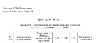
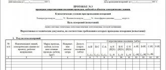
The finished protocol must be certified by the signature of the work contractor and the inspector appointed from the operational staff. To draw up measurement reports, it is allowed to use a regular notepad, but a more legal and reliable way is to fill out a special form (a sample of it is given below).
Sample insulation resistance measurement protocol
A pre-prepared protocol form contains paragraphs indicating:
- The procedure for carrying out measuring operations.
- The measuring instruments used.
- Basic standards for the controlled parameter.
In addition, the form of electrical wiring measurement reports contains ready-made tables prepared for filling out. In this form, the document is compiled on a computer only once, after which it is printed on a printer in several copies. This approach saves time on preparing documentation and gives measurement reports a finished, official look.
Low voltage power cables
Before measuring insulation resistance, you need to make sure that the cable is not supplied with dangerous voltage levels. The cable must be disconnected before starting work. Next you need to do the following:
- Using portable grounding, the residual charge is removed.
- The cable is cleaned of dirt.
- The insulation resistance value, which is indicated in the technical documents, is determined and, in accordance with it, the indicator is set on the scale of the measuring device.
The insulation resistance of low-voltage cable lines is measured using a device capable of operating with voltages up to 1000 Volts. The algorithm of actions is as follows:
- A megohmmeter is connected in pairs to all phase wires in the cable.
- Then each of the phase wires is considered in relation to the neutral wire.
- Each phase wire paired with a ground wire is measured.
- The neutral and ground wires are checked.
After working with each pair of wires, it is necessary to remove the residual charge.
Step-by-step instructions for measuring insulation resistance with a megohmmeter
Despite the fact that using a megohmmeter is not difficult, when testing electrical installations it is necessary to adhere to the rules and a certain algorithm of actions. To search for insulation defects, a high level of voltage is generated, which can pose a danger to human life. Safety requirements during testing will be considered separately, but for now we will talk about the preparatory stage.
Preparation for testing
Before testing the electrical circuit, it is necessary to de-energize it and remove the connected load. For example, when checking the insulation of home wiring in an apartment panel, it is necessary to turn off all AVs, RCDs and differential circuit breakers. The plug connections should be opened, that is, electrical appliances should be disconnected from the sockets. If lighting lines are tested, light sources (lamps) should be removed from all lighting fixtures.
The next step in the preparatory stage is the installation of portable grounding. With its help, residual charges are removed from the circuit under test. It is not difficult to organize portable grounding; for this we need a stranded conductor (necessarily copper), the cross-section of which is at least 2.0 mm2. Both ends of the wire are freed from insulation, then one of them is connected to the grounding bus of the electrical panel, and the second is attached to the insulating rod; in the absence of the latter, you can use a dry wooden stick.
The copper wire must be attached to the stick in such a way that it can touch the current-carrying lines of the circuit being measured.
Connecting the device to the line under test
Analog and digital megohmmeters are equipped with 3 probes, two ordinary ones, connected to the “Z” and “L” sockets, and one with two tips for the “E” contact. It is used when testing shielded cable lines, which are practically not used in everyday life.
To test single-phase household wiring, we connect single probes to the appropriate sockets (“ground” and “line”). Depending on the test mode, we attach alligator clips to the wires being tested:
- Each wire in the cable is tested against the other wires that are connected together. The wire under test is connected to the “L” socket, the remaining wires connected together to the “Z” socket. A similar connection diagram is shown in the figure.
Connecting a megohmmeter
If the indicators meet the standard, then testing can be completed, otherwise testing continues.
- Each of the wires is tested relative to ground.
- Each wire is checked in relation to other wires.
Test algorithm
Having considered all the main stages, you can proceed directly to the order of actions:
- Preparatory stage (fully described above).
- Installation of portable grounding to remove electrical charge.
- The voltage level is set on the megohmmeter; for household wiring - 1000.0 volts.
- Depending on the expected result, the resistance measurement range is selected.
- Checking the de-energization of the tested object, this can be done using a voltage indicator or a multimeter.
- Special crocodile probes of the measuring wires are connected to the line.
- Disconnecting portable grounding from the tested object.
- High voltage is supplied. In electronic megohmmeters, to do this, just press the “Test” button; if you are using an analog device, you should rotate the dynamo handle at a given speed.
- We read the device readings. If necessary, the data is entered into the measurement protocol.
- We remove residual voltage using portable grounding.
- We disconnect the measuring probes.
To measure the condition of other current-carrying conductors, the procedure described above is repeated until all elements of the object are checked, that is, we are talking about the end of measurements when testing electrical equipment.
Based on the test results, a decision is made on the possibility of operating the electrical installation.
Control cables
The measurement conditions and voltage for testing are determined depending on the specific type of cable. If the necessary technical information is missing, then this is done as for power cables up to 1 kV.
An employee with the appropriate clearance has the right to carry out measurements. Before checking, the cable is disconnected, then the residual charge must be removed. The device is connected to the cable cores using probes with insulated handles. For measurements, you will need a megohmmeter capable of operating with voltages from 0.5 to 2.5 kV.
Insulation resistance measurement is carried out as follows:
- The required core is taken to the side and connected to the “L” (line) socket, and the rest are connected together and connected to ground.
- Then the resistance is measured. This operation is performed for each of the wires that make up the cable. The duration of each test cannot be less than a minute.
After the series of tests is completed, it is necessary to remove the residual charge and wait a few minutes. After this, the measurements are repeated. The duration of the pause depends on the technical characteristics of the device and the features of the cable. After completing the procedure, it is necessary to calculate the average values of the insulation resistance of the wires.
Test methods used
Even before checking the condition of the insulation, it is important to decide on the object where you want to evaluate its quality. It can be:
- Electrical wiring.
- High voltage power cables.
- Low voltage power lines.
- Control wires.
For each of these electrical categories, individual methods for measuring insulation resistance are selected. Let's consider all the listed options in more detail.
Wiring
Before starting measurement procedures, electrical wiring and distribution boxes are inspected for breaks and obvious damage. After this, the places where the wires are connected to standard sockets and switches are examined.
Important! It is allowed to begin measuring insulation resistance only after the wiring is completely de-energized and all consumers at the facility are disconnected from it.
Measuring the insulation resistance of electrical wiring using a digital device Fluke-1507
In a single-phase network, to determine the required parameter, you will need to perform the following operations:
- First, the megohmmeter probes are connected between the phase and neutral conductors of the wiring.
- Then the insulation resistance between the phase and central conductor of the protective grounding is determined.
- The number of measurements taken corresponds to the set of wires in the line.
If, when taking readings, the megohmmeter shows a resistance of less than 0.5 Mohm, the electrical line will have to be divided into shorter segments. Based on the results of subsequent inspections of each of them, there is an area with unsatisfactory insulation quality. It will subsequently need to be completely replaced.
High voltage power cables (preparation)
Before measuring the insulation of a power cable, the latter is checked to ensure that there are no dangerous voltages on it. In addition, to prepare the measuring circuit, you will need to perform the following operations:
- First of all, the residual charge must be removed from the current-carrying conductors using portable grounding.
- Then the cable is completely cleaned of dust and dirt that interfere with the measurement process.
- After this, you will need to familiarize yourself with the cable’s passport data (the required parameter obtained from the results of factory tests is indicated there).
- The last operation is necessary in order to determine in advance the operating limit set on the device.
Preparing a cable line for insulation resistance measurements
Important! Before measuring the cable insulation resistance, it is necessary to carry out a control check of the megohmmeter for serviceability.
This operation consists of monitoring the readings on the instrument scale with the measuring ends closed and open. In the first case, the arrow moves closer to “zero”, and in the second case it shows “infinity”.
Power cables (measurements)
Measuring insulation resistance with a megohmmeter begins with a control check of each phase in relation to a grounded steel shell. And only after this the resistance between the individual cores is checked (photo on the left). In the process of taking readings, it is unacceptable for the measuring ends to come into contact with each other, as well as to come into contact with grounding structures and the steel shell.
a) the insulation resistance between the phase and the grounded sheath of the cable is measured, b) the resistance between the phases of the cable line is measured, respectively, “A” - “B”, “B” - “C” and “A” - “C”.
If it is found that the insulation resistance is below the permissible level, additional measurements are carried out in accordance with the requirements of the Electrical Installation Regulations. They involve measuring the insulation of all phases in relation to the ground and estimating the conductivity between phase conductors.
Please note: To improve the accuracy of readings indicating the value of wire insulation resistance, several measurements are taken.
Their total number varies: for a 3-core cable within 3-6 measurements, and for a five-core cable it may require 4, 8 or even 10 approaches.
Measuring the insulation resistance of a power cable in a private home
Since there are several measurement schemes for three-phase circuits, you should familiarize yourself with the option proposed by the manufacturer using the same passport. Before accurate readings are displayed on the megohmmeter scale, according to GOST 3345, at least 60 seconds must pass, but no more than 5 minutes (from the moment the ends are connected and high voltage is applied). If during this time, due to high humidity, for example, it was not possible to determine the readings (the needle did not deviate by the calculated value), the operation will have to be performed again.
Scheme for measuring the insulation resistance of a high-voltage cable
Before retesting, the residual charge must be removed again by applying grounding. Then you will need to switch the device to the desired limit and repeat the control measurements. According to safety regulations, this operation must be carried out with dielectric gloves. It is recommended to follow the instructions in pp. 1.7.81, 2.1.35 PUE, which stipulate safe work conditions. The main ones are given below.
- for zero operating and protective busbars, the insulation must be equivalent to the protective coating of phase conductors;
- on the side of the supply voltage sources and its receiver, the neutral conductors should be disconnected from the grounded elements of the circuit;
- Measurements in power electrical wiring are carried out only when the voltage is completely removed and the input circuit breakers or switches are turned off.
The last point is supplemented by the mandatory requirement to remove the fuses, turn off all existing receivers and unscrew the light bulbs. The measurement schemes proposed in the instructions differ only in their number (4 and 8 instead of 3 and 6) and the need to use the “Screen” protective terminal on the megohmmeter.
Low voltage power cables
When working with low-voltage power lines, they are first checked to ensure that there are no dangerous voltages on their elements. Similar to the high-voltage cables already discussed, before examining these products, you will need to perform the following operations:
- First, a dangerous residual charge is removed from the current-carrying conductors using portable grounding.
- Upon completion of this operation, the cable sheath and its working cores are completely cleaned of dust and dirt.
- Then the documents (passport, for example) are studied, which indicate the standardized insulation resistance for the test sample.
- The last operation is carried out with the aim of approximate estimation of the measured value and selection of the desired measurement limit on the device.
To carry it out, take a megohmmeter designed for a generation voltage of 1000 Volts. Upon completion of all preparatory operations, proceed directly to measurements. Their order can be represented as the following sequence of actions:
- First, the required resistance is measured between the phase conductors of the cable line under test (“A” - “B”, “B” - “C” and “A” - “C”).
- Then, the insulation state of each phase relative to the neutral wire (N) is assessed in turn.
- The following is a sequence of measurements between each phase and the PE ground wire (carried out when checking a three-phase five-core conductor).
- To carry out the last operation, the neutral wire is disconnected from the grounding bus, after which the resistance between the N and PE conductors is measured.
Upon completion of each next action, it is necessary to “remove” the residual charge in the manner already described.
Control cables (preparation)
In this case, it will be possible to check the resistance only if the following requirements are met:
- The ambient temperature should be within the range from –30 to +50 degrees (with humidity up to 90%).
- They influence the admissibility of working with a particular type of megohmmeter in a particular situation.
- The measurement conditions (the length of the monitored cable, in particular) and the operating voltage are selected depending on its brand.
- If there is no passport for the cable product, a test voltage of 0.5 to 1 kV is applied to it according to the PUE (Table 1.8.39).
Please note: It is allowed to carry out tests together with all equipment connected to the cable (magnetic starters and protective relays installed in the line).
Before testing resistance, be sure to be familiar with safe cable handling techniques. They boil down to compliance with the following rules:
- Only specialists with the 3rd tolerance group or higher are allowed to take measurements under voltages up to 1 kV;
- the cable under test must be disconnected from the power supply, after which the residual charge is removed from it;
- Before starting measuring operations, you must ensure that there are no unauthorized persons near this place.
Voltage is applied to the current-carrying conductors using probes with insulated handles of the “holder” type. In addition, for safety reasons, it is prohibited to touch the conductive busbars to which the turned on megohmmeter is connected. Upon completion of the current tests, the residual charge must be removed from the control part of the cable. To do this, portable ground connections are used or a special function of the measuring device is activated (available in some models).
Control cables (work order)
The procedure for testing the insulation protection of control cables is similar to the provisions developed for low-voltage wiring lines (up to 1 kV). An exception is the clause on disconnecting current-carrying conductors from load equipment. Due to the small magnitude of the transmitted signal, this is not necessary in this situation.
To carry out the tests, you will need a digital or analog megohmmeter, according to the passport, designed for operating voltages from 0.5 to 2.5 kV. The order of measurements in this case looks like this:
- First, on the side of the cable being tested, the leads of the current-carrying conductors are carefully cut and cleaned, and then separated from each other to some distance (about 5-10 cm).
- Next, each wire is connected in turn to the “+” of the megohmmeter, and all other wires are twisted and connected to the “ground”.
- The second input (“–”) of the device is also connected there (see figure below).
- Test voltage is then applied to the working cable.
- When using modern digital devices, an external power source (electrical network or battery) will be required.
- The tests last for at least a minute, after which the result is recorded on a scale and then entered into the logbook.
- Further, all the described operations are performed with each signal core separately (it is connected to the device, and all others are twisted and connected to the second contact, which in turn is connected to the ground.
At the end of the measurements, the residual charge is removed from the working conductors, and the megohmmeter is allowed to “settle” until the next series of tests. The duration of the pause allocated for this depends on the specific type and brand of the device. The following measurements are carried out taking into account the frequency of the insulation test.
Safety regulations
The technique used to measure insulation resistance must ensure that safety requirements are met. You must adhere to the following rules:
- All manipulations when measuring insulation resistance must be performed with dielectric gloves. Failure to comply with this requirement increases the risk of injury.
- When carrying out measurements, no unauthorized persons should be near the equipment. It is advisable to post warning posters near the place of work.
- When using probes, only touch their insulated parts.
- Before each measurement, it is imperative to remove the residual charge using a portable grounding device.
- It is important to check the humidity level. If it is higher than permissible, measurements cannot be carried out, as this can be dangerous.
Documentation
After completing the inspection, all measurements must be reflected in a special document. It must, in particular, include the following information:
- The date the check was performed.
- Amount of work completed.
- Information about the employees who carried out the inspection.
- It is necessary to indicate which device the measurements were used with.
- Connection diagram in accordance with which the work was carried out.
- It is necessary to reflect the conditions for performing the check. For example, it is necessary to indicate at what temperature the measurements were carried out.
- A table is compiled in which it is necessary to reflect that exactly this insulation resistance was obtained during the measurements.
Having such a document will be useful, for example, in the event of an emergency. It will indicate that all necessary operating conditions have been met. The document confirming the measurements must be certified by the signature of the inspector and the employee who carried out the inspection.
When should an inspection be carried out?
When using electrical equipment, you must be sure that it is functional and completely safe. To do this, it is necessary to regularly check the insulation resistance. Usually the time for it comes in the following situations:
- Immediately after production of the product.
- Before installation work begins.
- When putting the facility into operation.
- After an emergency has occurred.
- If serious defects are detected.
- In connection with the performance of maintenance within the time limits provided for by regulatory documents.
Failure to meet deadlines will increase the risk of problems occurring. Typically, enterprises draw up plans for such work in advance. For cables used outdoors, these measures are carried out annually, and for cables used indoors - once every three years.
Design and principle of operation of a megohmmeter
The aging of electrical wiring insulation, like any electrical circuit, cannot be determined with a multimeter. Actually, even with a rated voltage of 0.4 kV on the power cable, the leakage current through microcracks in the insulating layer will not be so large that it can be detected by standard means. Not to mention measuring the resistance of intact cable insulation.
In such cases, special devices are used - megohmmeters, which measure the insulation resistance between the motor windings, cable cores, etc. The principle of operation is that a certain voltage level is applied to the object and the rated current is measured. Based on these two values, the resistance is calculated according to Ohm's law for a section of the circuit (I = U/R and R=U/I).
It is typical that megohmmeters use direct current for testing. This is due to the capacitance of the measured objects, which will pass alternating current and thereby introduce inaccuracies in the measurements.
Structurally, megaohmmeter models are usually divided into two types:
- Analog (electromechanical) - old-style megohmmeters.
Analog megohmmeter - Digital (electronic) – modern measuring devices.
Electronic megohmmeter
Let's consider their features.
Electromechanical megohmmeter
Let's consider a simplified electrical circuit of a megohmmeter and its main elements
Simplified diagram of an electromechanical megohmmeter
Designations:
- A manual DC generator, a dynamo is used as such. As a rule, to obtain a given voltage, the rotation speed of the hand generator handle should be about two revolutions per second.
- Analog ammeter.
- An ammeter scale calibrated to indicate resistance measured in kiloohms (kOhm) and megaohm (MOhm). The calibration is based on Ohm's law.
- Resistance.
- KOhm/Mohm measurement switch.
- Clamps (output terminals) for connecting test leads. Where “Z” is the ground, “L” is the line, “E” is the screen. The latter is used when it is necessary to check the resistance against the cable shield.
The main advantage of this design is its autonomy; thanks to the use of a dynamo, the device does not require an internal or external power source. Unfortunately, this design has many weaknesses, namely:
- To display accurate data for analog instruments, it is important to minimize the mechanical impact factor, that is, the megohmmeter must remain stationary. And this is difficult to achieve by rotating the generator handle.
- The displayed data is affected by the rotational uniformity of the dynamo.
- Often the measurement process requires the efforts of two people. Moreover, one of them performs purely physical work - he rotates the handle of the generator.
- The main disadvantage of the analog scale is its nonlinearity, which also negatively affects the measurement error.
Note that in later analog megohmmeters, manufacturers abandoned the use of a dynamo, replacing it with the ability to operate from a built-in or external power source. This made it possible to get rid of characteristic shortcomings; in addition, the functionality of such devices has significantly increased, in particular, the voltage calibration range has expanded.
Modern analog model of megaohmmeter F4102
As for the principle of operation, it has remained unchanged in analog models and consists of a special gradation of the scale.
Electronic megohmmeter
The main difference between digital megohmmeters is the use of a modern microprocessor base, which can significantly expand the functionality of the devices. To obtain measurements, just set the initial parameters and then select the diagnostic mode. The result will be displayed on the information board. Since the microprocessor makes calculations based on operational data, the accuracy class of such devices is significantly higher than that of analog megohmmeters.
Separately, mention should be made of the compactness of digital megohmmeters and their versatility, for example, testing residual current devices, measuring ground resistance, phase/zero loops, etc. Thanks to this, comprehensive tests and all necessary measurements can be carried out with one device.