Sensors in the car system are “spies” that report the information they have collected to the main components of the car. There are many such parts in any car, but among them the main ones can be identified - for example, a sensor whose operation is based on the Hall effect. This sensor often fails, so it needs to be diagnosed regularly.
Where is the Hall sensor located and what does it look like?
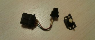
The Hall sensor is located in the distributor - more precisely, inside its cover. Remove it and you will see the sensor. It is responsible for generating a spark and acts as distributor contacts in a contactless ignition system. This is a controller that transmits information about the position of the motor system shafts to the control unit.
Externally, the device looks like a cylindrical element enclosed in a plastic case, to which a connector with wiring is connected. On top of the case is a magnetically conductive plate, which resembles a crown due to the slots. There are as many slots on it as there are cylinders in the engine. The main elements of the device are a permanent magnet and, in fact, a sensor.
Example of using an analog element
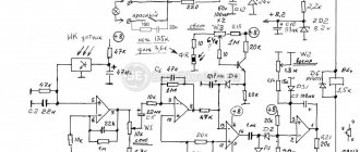
Let us consider, as an example, the design of a current sensor whose operation is based on the Hall effect.
Simplified circuit of a current sensor based on the Hall effect
Designations:
- A is a conductor.
- B – open magnetic conductor ring.
- C – analog Hall sensor.
- D – signal amplifier.
The operating principle of such a device is quite simple: the current passing through the conductor creates an electromagnetic field, the sensor measures its magnitude and polarity and produces a proportional voltage UDT, which is supplied to the amplifier and then to the indicator. https://www.youtube.com/watch?v=fmLs9WsKx3I
Why does the Hall sensor fail?
Damage to the sensor can manifest itself with different symptoms - even a professional can sometimes find it difficult to determine the exact cause. Here are the signs that indicate a sensor failure:
- the engine does not start well;
- idling with constant interruptions;
- at high speeds the car jerks;
- the spark on the candles disappears;
- the engine suddenly stalls.
The main reason for the failure of this part is trivial - dirt has accumulated. As soon as this happens, the DH signals immediately. “Miracles” begin to happen to the car. However, it is wrong to blame this device for all the troubles - a thorough check is needed.
A common cause of failure is a lack of contact in the wiring. In total, the device has 3 contacts - connecting it to ground, to plus, to the switch. One of the contacts could have oxidized, causing the electrical circuit to break.
Finally, the wire may simply break or break. This occurs due to the fact that the vacuum ignition corrector displaces the platform on which the DC is located, shifting the ignition angle. To avoid such a misfortune, the wiring must be secured so that it bends in a loop.
If the high-voltage wiring in the car is worn out and lies next to the sensor wires, a high-voltage breakdown is possible. Often breakdowns occur in wet weather, when the wheel drives into a deep puddle.
A breakdown may occur due to overcharging of the battery generator - when the DC experienced too much load and one of the parts burned out at the input of the switch.
Repair
There is no point in repairing Hall sensors, since the cost of this will exceed its cost, which is in the range of $3–5.
If, out of curiosity, someone wants to do repairs, then you can try to do this for automotive products, but the repair will not concern the very core of the sensor, but the “chip” and the cable: the capacitor often burns out, it and the wires can be resoldered. The cause of the malfunction may lie in soured contacts; they are cleaned.
How to check the Hall sensor in the distributor?
A common way to check is to simulate the presence of a sensor. This is the most effective way. It is suitable when there is electricity in the ignition system components and in the complete absence of a spark.
To check from the distributor, we remove the block for connecting the plugs. Then we activate the ignition of the car and, using small pieces of wire, close outputs 2 and 3. If there is a spark on the middle wire of the ignition coil, it means that the sensor has died for a long time. To detect the formation of a spark, we place the high-voltage wiring next to the ground.
Ring with a multimeter
It is necessary to measure the voltage that is generated at the output of the controller. If the device is working properly, the voltage will be within 20 volts.
First of all, you will have to remove the cover from the block connected to the distributor. Next we proceed like this:
- dismantle the main shielded wire from the distributor;
- connect it to ground (to prevent the risk of accidental discharge);
- activate the ignition;
- remove the distribution block;
- set the multimeter to the DC 20 V position;
- We connect the negative probe to ground;
- We will need the positive one to measure the voltage.
There are 3 multi-colored wires on the distributor block. On red, the voltage should be around 12 V. The same value is the norm for the green wire. But on white it should be zero. If the device is in sound mode, a ringing sound will appear when the probe touches the white wire. This is evidence of a normal connection of the wire to ground.
This is how we made sure that all impulses were present on the DH. Now we take small nails prepared in advance and insert them: one into the green (middle) wire, the other into the white (ground). We mount the block into the distributor. Carnations act as conductors. The fact is that on the other side of the block there is no contact base, and the wiring cannot be exposed. We bring the positive probe to the middle wire, the minus probe to ground. The device should show 11.2 V (approximate value). We turn the crankshaft. If at the lower point the readings correspond to 0.02 V, and at the upper point 11.8 V, this is normal. Significant deviations from these readings indicate a problem.
Reasons for DH failure
The position sensor can be damaged by the following factors:
- serious overheating of the power unit (the temperature should exceed 150-180 degrees);
- power surges;
- penetration of moisture into the body of the electric motor or accelerator handle;
- mechanical damage.
A clear sign of a DH malfunction is twitching of the motor-wheel at start-up when the accelerator is applied. To diagnose such a failure, we only need a voltmeter.
How to replace a Hall sensor on a car?
Since repairing a faulty DC is impractical, we prepare the tools and begin to replace it. You will need:
We proceed according to this scheme:
- We turn off the engine and open the hood.
- Disconnect the pipe from the vacuum regulator.
- Remove the distributor cover.
- Disconnect the connector on the DH.
- We unscrew the holder plate with the “13” key. After this, you can remove the distributor.
- Take a hammer and use it to knock out the spring clutch screw.
- Remove the screws securing the vacuum regulator. We pull it out - access to the household is open.
- Using a screwdriver, unscrew the screws securing it and remove the mechanism. We replace it with a new one.
Assembly is done in reverse. After completing the procedure, be sure to drive the car to make sure everything was done correctly.
The reasons for the failure of the Hall sensor are different, but in any case the sensor must be replaced immediately. Repairing the device is useless - you shouldn't even think about it. However, before dismantling the Hall device, make sure that it is the one causing all the problems.
Many motorists today are interested in the issue of high-quality testing of the hall sensor - the mini-regulator of the ignition distributor of modern cars. Having learned to do this yourself, you can safely go on long trips without fear of finding yourself helpless in front of a car alone. A classic test of a hall sensor using a DC measuring device is presented in the article.
Connecting large electrical loads
The output power of the Hall sensor is very low (10–20 mA), as a result of which it cannot directly control high electrical loads. The problem is solved quite simply: the connection is made by adding an NPN transistor to the device, through which current flows to the output. The specified part acts as a receiver; when it is saturated, it is activated as a switch. The transistor grounds the output contact, thus closing it when the flux density of the set values for “on” increases.
There are various configurations of the transistor switch, but the main thing is that the device provides a 2-cycle output, allowing it to draw the required current to control large loads.
The role of the sensor in the SZ system
ATTENTION! A completely simple way to reduce fuel consumption has been found! Don't believe me? An auto mechanic with 15 years of experience also didn’t believe it until he tried it. And now he saves 35,000 rubles a year on gasoline! Read more"
If the sensor or DC malfunctions, problems arise related to the direct functioning of the engine. The car may not start at all or behave extremely poorly on the road. Is it really possible for such a small element as DH to have such a powerful effect on a car’s engine? Yes, yes.
What is DH? This is a controller capable of sensitively responding to any changes in the magnetic field. If the DC is faulty, the injector stops functioning.
The interaction of the DC with the ignition system in the electrical sense is carried out through a switch or conductor. As a result, a magnetic field appears.
Checking the sensor with a multimeter
You can check the DH in different ways. One popular diagnostic option is a multimeter or voltmeter. This verification method has two options. Let's look at how to check a car's hall sensor in both cases.
1st method
To carry out diagnostics, you need to find a working voltmeter or multimeter that is set to measure DC voltage (direct current) in the range of 20 Volts. In addition, you will need to stock up on 2 iron pins, through which the DC will be checked.
Before checking the hall sensor, you will need to remove the rubber boot from the block, which is connected to the distributor and directly to the DH.
- remove the main armored wire from the distributor;
- We connect it to the arrester or to ground.
This is done in order to exclude the accidental occurrence of a discharge, because this may contribute to starting the engine during the test.
- turn on the ignition;
- remove the block from the distributor;
- set the mode on the multimeter to DC 20 V;
- We connect the negative terminal of the device to ground (any part of the car body);
- the positive probe of the device will serve as a voltage meter.
The block going to the distributor has three wires: red, green and white (colors may be different). On the red wire, the voltage of the device should show 11.37 or close to 12 V. On the green or middle wire, the value is also close to 12 V. And finally, on the last - white wire, the value is 0.
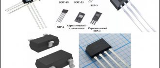
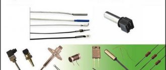
Types and scope of application
Despite the variety of elements that use the Hall effect, they can be divided into two types:
- Analogue, using the principle of converting magnetic induction into voltage. That is, the polarity and voltage directly depend on the characteristics of the magnetic field. Currently, this type of devices is mainly used in measuring technology (for example, as current, vibration, rotation angle sensors).
Hall effect current sensors can measure both AC and DC current - Digital. Unlike the previous type, the sensor has only two stable positions, indicating the presence or absence of a magnetic field. That is, operation occurs when the intensity of the magnetic field has reached a certain value. It is this type of device that is used in automotive technology as a sensor for speed, phase, camshaft position, as well as crankshaft, etc.
It should be noted that the digital type includes the following subtypes:
- unipolar - triggering occurs at a certain field strength, and after it decreases, the sensor returns to its original state;
- bipolar - this type reacts to the polarity of the magnetic field, that is, one pole turns the device on, and the opposite pole turns it off.
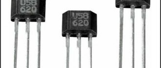
Appearance of a digital Hall sensor
As a rule, most sensors are a component with three pins, two of which are supplied with bi- or single-pole power, and the third is a signal one.
How to check the Hall sensor
Car owners are often in a hurry and spend money on buying a new part. But this is a mistake. First you need to make sure that the reason lies in a specific part.
That's why you need to know the signs of a breakdown, how to check the Hall sensor and replace it yourself.
Purpose of the Hall sensor
Hall sensor (HL) is a device that determines the angle between the positions of the crankshaft and camshaft of the car. The product is used in cars of many European and domestic brands - Audi, Passat, Volkswagen, BMW, Suzuki and others.
DH is an indispensable element in a car equipped with contactless ignition. In the contact system, this unit is part of the distributor.
Thanks to the information received from the DC, the spark plugs fire in a timely manner and ignite the flammable liquid . Failure or malfunctions lead to starting problems or the inability to start the car.
Replacement
Let's look at the standard procedure for replacing a VAZ hall sensor. The process is simple even for novice car enthusiasts.
The procedure for replacing the Hall sensor:
- Remove the distributor and dismantle its cover.
- Align the marks of the gas distribution mechanism and crankshaft.
- Remove the fasteners with a wrench. In this case, it is recommended to mark and remember (take a photo with a smartphone) the location of the distributor.
- Clamps and stoppers in the housing are also dismantled.
- Remove the shaft from the distributor.
- Disconnect the terminal contacts, unscrew the mounting bolts, and pull out the detector through the slot.
- Connect the sensor correctly - proceed in reverse order.
There is no connection diagram in the car as such, since the sensor has a power cable with a plug, that is, the pinout is already there, and the chip is equipped with “foolproof protection” and keys (protrusions) that make incorrect installation impossible. The detector box has holes for mounting bolts.
In other devices, the Hall effect sensor is soldered according to the location of the legs and contacts under them on the board. If you take a “bare” sensor, however, and if there is a housing, the arrangement of contacts is similar. The required leg for soldering to the board is determined simply, as in the diagram below.