NTC sensors with resistors, with a resistance that is particularly sensitive to temperature, are common due to their simplicity, low cost, and efficiency. Negative Temperature Coefficient means that as temperature increases, the sensor resistance decreases. The product is installed wherever it is necessary to monitor the temperature, in devices that depend on it: refrigerators, washing machines, boilers, heated floors. Thermal sensors are used for homemade products, for example on Arduino. The equipment picks up the signal from the STC sensor and operates according to the settings. Let's consider the operating principle, types, characteristics and capabilities of NTC detectors and thermistors, where they are used, how to calculate, select.
Concept of NTC temperature sensors
In normal use, resistors do not need their resistance (R) to change with temperature. The dependence is minimal, otherwise the element would influence the circuit, for example, the diode would change the intensity of the glow in an uncontrolled manner. But if it is required that its brightness be a function of temperature, then a thermistor is used - a resistor, resistor. which is sensitive even to small shifts in t°. This property is reflected by the main characteristic - the curve of the R/T graph.
Negative Temperature Coefficient - “negative (minus) coefficient t°”, also known as NTC. This is the most common type of temperature sensors, as they are cheaper than all others, with good efficiency, sufficient for most devices.
Advantages, comparison with other temperature sensors
Advantages:
- significant steepness of the R/T curve, small deviations from nominal values, which indicates good sensitivity;
- minimum response time;
- significant TCS values, that is, greater sensitivity, increased degree of change in R depending on t° (about 2–10% per Kelvin);
- resistance shows a large, precise, predictable decrease as operating temperatures at the resistor core increase;
- extreme compactness, thermistors are suitable for any board, even for spaces measured in mm (there are standard sizes in the form of beads), so sensors with them are compact;
- better strength, reliability, stability, suitability for extreme environments, noise immunity in its operating ranges;
- economical, less labor-intensive to maintain. If the curve is correct, then calibration will not be required during installation and throughout the entire service life;
- It is easy to find out the required resistance at a specific temperature from the curve.
Advantages and disadvantages:
| Compared to RTD | Compared to thermocouples | ||
| Flaws | Advantages | Advantages | Flaws |
| less accurate (but not much) t° range less than RTD | response is faster | accuracy is similar with other advantages | Smaller range, thermocouples operate at higher temperatures (+600° C) |
| greater sensitivity, stability, correctness within one’s working framework; | |||
| simple operation, which reduces the price, no amplifiers, interpreters, etc. are required | |||
| smaller, convenient size | |||
| low cost (one of the main advantages) | |||
| resistance to shocks and vibrations is higher | |||
Parameter coefficients and current-limiting properties are several times better than those of Si temperature sensors. An order of magnitude higher (from 10 times) than that of RTDs (metal thermal detectors).
Compared to RTDs (platinum), the R/T line is steeper, which reflects better sensitivity. But still, the first ones are the most accurate (±0.5% of the measured t°) and they are the best for the limits of −200...+800° C, which is wider than NTC, but the advantage of the latter is that it is cheap and simple.
Program code for Arduino
The code is provided with a lot of comments to help you understand the logic of the program.
Basically it measures the voltage across the divider, calculates the temperature and then displays it on the serial port terminal.
For fun, there are also some "if...else" statements added to show how you can act depending on the temperature range.
//================================================================ ============================== // Constants //============== ===================================================== =============== // Thermistor related: /* Here we have several constants that make editing the code easier.
Let's go through them. Reading from the ADC may produce one value on one sample, and then a slightly different value on the next sample. To avoid the influence of noise, we can read the values from the ADC pin multiple times and then average the values to get a more constant value. This constant is used in the readThermistor function. */ const int SAMPLE_NUMBER = 10; /* To use the beta equation, we must know the value of the second resistor in our divider. If you are using a resistor with a large tolerance, such as 5% or even 1%, measure it and place the result in ohms here. */ const double BALANCE_RESISTOR = 9710.0; // This helps to calculate the resistance of the thermistor (see article for details). const double MAX_ADC = 1023.0; /* This constant depends on the thermistor and should be in the datasheet, or see the article on how to calculate it using the beta equation. */ const double BETA = 3974.0; /* Required for the conversion equation as a "typical" room temperature. */ const double ROOM_TEMP = 298.15; // room temperature in Kelvin /* Thermistors have a typical resistance at room temperature, we will indicate it here. Again, necessary for the equation to transform. */ const double RESISTOR_ROOM_TEMP = 10000.0; //================================================================ ============================== // Variables //============== ===================================================== =============== // Here we will store the current temperature double currentTemperature = 0; //================================================================ ============================== // Pin declarations //============= ===================================================== ================ // Inputs: int thermistorPin = 0; // ADC input, voltage divider output //========================================= ====================================== // Initialization //====== ===================================================== ======================= void setup() { // Set the port speed for sending messages Serial.begin(9600); } //=============================================================== ================================ // Main loop //========================== ===================================================== ================= void loop() { /* The main loop is quite simple, it prints the temperature to the serial port monitor. The heart of the program is in the readThermistor function. */ currentTemperature = readThermistor(); delay(3000); /* Here we describe what to do if the temperature is too high, too low or just right. */ if (currentTemperature > 21.0 && currentTemperature < 24.0) { Serial.print("It is "); Serial.print(currentTemperature); Serial.println("C. Ahhh, very nice temperature."); } else if (currentTemperature >= 24.0) { Serial.print("It is "); Serial.print(currentTemperature); Serial.println("C. I feel like a hot tamale!"); } else { Serial.print("It is "); Serial.print(currentTemperature); Serial.println("C. Brrrrrr, it's COLD!"); } } //=========================================================================== =================================== // Functions //========================== ===================================================== ================= //////////////////////////// //// // readThermistor /////// //////////////////////////// /* This function reads the values from the analog pin as shown below. Converts the input voltage to a digital representation using analog-to-digital conversion. However, this is done several times so that we can average the value to avoid measurement errors. This averaged value is then used to calculate the thermistor resistance. The resistance is then used to calculate the thermistor temperature. Finally, the temperature is converted to degrees Celsius. */ double readThermistor() { // variables double rThermistor = 0; // Stores the thermistor resistance value double tKelvin = 0; // Stores the calculated temperature double tCelsius = 0; // Stores temperature in degrees Celsius double adcAverage = 0; // Stores the average voltage value int adcSamples[SAMPLE_NUMBER]; // An array to store individual // voltage measurements /* Calculate the average thermistor resistance: As mentioned above, we will read the ADC values multiple times to get an array of samples. A small delay is used for the analogRead function to work correctly. */ for (int i = 0; i < SAMPLE_NUMBER; i++) { adcSamples = analogRead(thermistorPin); // read the output value and save delay(10); // wait 10 milliseconds } /* Then we simply average all these samples to "smooth" the measurements. */ for (int i = 0; i < SAMPLE_NUMBER; i++) { adcAverage += adcSamples ; // add up all selections. . . } adcAverage /= SAMPLE_NUMBER; // . . . we average them using division /* Here we calculate the resistance of the thermistor using the equation described in the article. */ rThermistor = BALANCE_RESISTOR * ( (MAX_ADC / adcAverage) - 1); /* The beta equation is used here, but it is different from what was described in the article. Do not worry! It has been re-engineered to produce a more "pretty" formula. Try simplifying the equation yourself to practice algebra. Or just use the one shown here or the one in the article. In any case, everything will work! */ tKelvin = (BETA * ROOM_TEMP) / (BETA + (ROOM_TEMP * log(rThermistor / RESISTOR_ROOM_TEMP))); /* I will use Celsius to display temperature. I did this to see the typical room temperature, which is 25 degrees Celsius. */ tCelsius = tKelvin - 273.15; // convert kelvins to celsius return tCelsius; // return temperature in degrees Celsius }
Principle of operation
The sensor alloy changes conductivity at different temperatures. Resistance decreases as it increases, and increases as it decreases. Electrical parameters change, which is recorded by the circuit.
The microcontroller of the serviced device, based on the received data, taking into account the specifications of the detector, calculates the t° shifts. Then it sends a signal to the executive unit (relay, heater, cooling system) to act at a particular t° level.
Example: taking into account the described algorithm, the voltage is controlled at the input of the thermostat comparator, adjusted according to the temperature characteristic, and it undergoes changes.
The NTC sensor itself is not an electronic device, it only records. It is based on a nonlinear dependence of resistivity. resistor depending on the temperature of the environment. The operating scheme may be simpler: a simple output on a value display or a relay can react immediately.
Sensors are sensitive to electromagnetic radiation and fields, so they are shielded or mounted at a distance from the sources of such phenomena (power wires).
Premium technology
Dishwashers and other appliances are manufactured in Germany using high quality materials and advanced technology. On our website you will find a huge number of built-in and free-standing solutions for the kitchen and home. All devices are equipped with a Wi-Fi module for integration into a home network ( [email protected] ). You can control their work remotely from a laptop or smartphone.
Reliable equipment with a modern design will perfectly emphasize the high social status and impeccable sense of style of its owner. The official guarantee for all Miele products ordered in the company’s online store is 24 months. Delivery of goods is carried out in Moscow, the Moscow region (by courier service) and other regions of Russia (by transport companies).
How are they different from thermocouples?
NTC should not be confused with thermocouples: although the tasks are similar and there is a connection with electrical parameters, the principle is different. For the former, it is based on a change in the resistance of the sensitive part, for the latter, on the potential difference that changes during temperature transformations, created by two segments from different alloys with different electrical properties.
The NTC sensor is made of one solid piece of alloy, and the thermocouple is made of two metals, and measurements are based precisely on transformations of its resistance, and not on potential differences.
Design of temperature sensors and NTC thermistors
Other names are resistive sensors, thermistors, thermal or thermistors, NTC temperature sensors or resistance thermometers (but specifically with an NTC thermistor, not to be confused with RTDs and products with other sensitive parts).
The NTC sensor consists of a resistive (sensitive) segment - a thermistor and wires (legs) for supplying current to it.
The thermistor is made by powder method, baking.
Materials: oxides, halides, chalcogenides. Semiconductors (often polymer) are used; they themselves have a TCS “−”. For the body and outer coating - ceramics, glass, epoxy.
Standard sizes
Standard sizes of thermistors themselves: rods, tubes, disks, beads, plates, drops, tablets. Sizes 1–10 µm to several mm and 1 cm.
There are also SMD formats and micro-rectangles.
We can immediately distinguish between the sensors as ready-to-use products and the “bare” thermistors themselves.
Sensors as devices can be made in any form, housing according to the manufacturer’s decision, for example, probes, probes, “chips” with connectors, in a waterproof housing, with threads, on a long cable.
Sensors as ready-made devices
Automotive:
Invoices. On the surface of structures. Examples: T2C-NTC 10K for −50…+150° C; ALTF02 S+S for collecting data from solid objects (pipes).
Channel, submersible. For cavities. T3-NTC 10K with 30 cm cable, for +50…−50° C; T2I-NTC 10K, 6.5 cm, −50…+150° C; TF43T and TM54 for liquids in pipes and containers.
External. For weather-sensitive complexes, on external walls (ATF01 S+S Regeltechnic).
Rooms. For interior spaces, apartments, offices.
Multifunctional. They combine other sensors to study not only temperature, but also pressure, density, etc.
Beaded
Beads, ball, drop, Ø 0.075 to 5 mm. Made of lead wires, an alloy with platinum, sintered in a ceramic, glass-ceramic shell. Better response and stability, their operating temperatures are higher than those of disk variants and chips.
Disadvantages: higher fragility, no interchangeability, require individual calibrations. There are no exact standards for their R/T ratings.
Discs, records, chips, tubes
Disc-shaped products with surface contacts. The shape is larger, the reaction is slower than that of balls. But due to their increased dimensions, they have good dissipation (power to increase temperature by 1 degree). Since the energy dissipated is proportional to the square of the current, they work better with high currents than balls.
Disc ones are made by pressing powder-like oxides into a round matrix, then sintered. Chips are injection molded, the suspension is distributed into a thick ball, then dried and cut. Dimensions Ø 0.25…25 mm.
Interchangeable, but there are errors, the minimum permissible deviation is considered to be at least 0.05 ° C within 0...+70 ° C. A standard 10 kOhm thermistor within the range of 0…+100 has coefficients close to the following:
Tube thermistor:
Encapsulated
Encapsulated ones resemble wafers, tablets, and may be similar to other types. The peculiarity of their coating is that it is especially sealed, airtight (bubble, capsule, container), made of fiberglass. For high temperatures, from +150° C, for boards where special strength is required. This design increases stability, protection, Ø 0.4…10 mm.
NTC and PTC temperature detectors
There are two types of thermistors: the direction of the dependence of R on temperature and the TKS mechanism differ. The word before the abbreviation of the phrase “Temperature Coefficient” reflects this nuance:
- Negative. NTCs we are considering. With negative t° coefficient. As the temperature increases, the resistance decreases;
- Positive, PTC. The second name is posistors. With positive t° coefficient. R increases.
For NTC thermistors, mixtures of multicrystalline transition metal oxides (MnO, CoOx, NiO and CuO), semiconductors of certain types (A, B), and glass-like (Ge and Si) are used. And PTC (posistors) consist of solids based on BaTiO₃; this alloy has a positive reaction (TCR). But the differences in operation are mainly only in the direction of the R/T relationship.
The most popular mid-range NTC temperature detectors: TKS −2.4…-8.4%/K, with wide resistance limits. (1...106 Ohm). If we talk about PTC, then these numbers are 0.5...0.7%/K, they are often made of silicon, their resistance, unlike NTC, is close to linear.
PTCs are used on cooling equipment, temperature stabilization in electronic circuits, and as self-regulating heating parts. Their R increases as their heating increases (PTC heaters), such a spare part will never overheat, and always produces stable heat output over a significant voltage range.
The areas are extremely similar, and the principle is basically the same - it all depends on what is required, negative or positive TCS:
- NTC monitors the temperature drop;
- PTC - for a promotion.
What types and shapes of thermistor are available in the market
Thermistors come in many forms - disk, chip, ball or rod - and can be surface mounted or integrated into a system. They can be encased in epoxy resin, glass, phenol baked or painted. The best shape often depends on what material is being controlled, such as solid, liquid or gas. For example, a beaded thermistor is ideal for embedding into a device, while a rod, disk, or cylindrical head is best suited for optical surfaces.
Select a shape that provides maximum surface contact with the temperature-controlled device. Regardless of the thermistor type, the connection to the device being controlled must be made using thermal conductive paste or epoxy adhesive. It is usually important that this paste or glue is not electrically conductive.
Types of NTC thermistors
According to the range of values of the serviced NTC environment there are:
- low temperature. For below 170 K (Kelvin, maybe in Celsius);
- average, 170...510 K;
- high, from 510 K;
- ultra-high, 900…1300 K.
A separate type is combined, with indirect heating. They combine a resistor and a heating element “galvanically isolated” from it, which sets the temperature and, accordingly, the resistance. They are used as variable resistors controlled by the voltage supplied to their heating part.
Model range of Miele dishwashers
The German brand offers you multifunctional dishwashers designed to load from 9 to 14 place settings. The range includes built-in and free-standing (for example, Miele PG8130) models. The devices can be built into a furniture set partially (G7310 SCi) or completely (G7150 SCVi). Narrow and full-size dishwashers are available (45 and 60 cm wide, respectively).
An intuitive interface with a display provides access to a large number of automatic washing programs (up to 13) and other popular options. The machines are distinguished by well-thought-out internal zoning, low consumption of water and household chemicals. Miele dishwashers operate quietly and economically; the energy efficiency class of many models even exceeds A+++.
Calculation, selection of NTC thermistors
They determine which thermistor is suitable by using the R/T curves, by creating graphs and tables of RT values, and by formulas. The procedure is complex, there are entire brochures and separate articles, so we will only indicate the basics.
The best, albeit complex, calculation formula is that of “Steinhart (Steinhart) - Hart”:
Calculations are usually done by radio electronics fans and specialists, especially for homemade products. It will be easier to select an element with a similar specification, and also use ready-made recommendations from specialists; the information is available online on special sites. There are hundreds of modifications of thermistors; accordingly, the specification tables are very large. Often a specific batch of similar series of thermistors has its own data.
There are hundreds of NTC thermistor specifications:
But still, calculations in most cases are extremely desirable, even if there is data from the manufacturer on the parameters and recommendations, since thermistors have highly nonlinear properties. Different copies of the same specification, even, for example, with the same values of B25/100 (sensitivity, we will consider below), may have different shifts R. Therefore, the formulas for this parameter provide only an approximate estimate. Accurate results require complex calculations.
Sensors for household or other appliances in factory standard sizes are devices in a housing that are completely ready for use, and so on, all the necessary calculations are made by the manufacturers.
Parameters for selection (usually displayed as graphs, diagrams):
- CVC;
- temperature/resistance ratio curve;
- heat capacity, dissipation constant;
- R values;
- tolerances;
- temperature Range. It is within their boundaries that NTC sensors can perform better than all similar products;
- time constant: the period for transition from one t° value to another. This is the period in seconds required to achieve 63.2% difference in t° from the initial reading to the final reading;
- sensitivity: level of response to temperature changes;
- stability of the controller while maintaining a constant temperature through feedback from the sensor.
First order approximation
The t°/Ohm dependence (RT graph) has significant nonlinearity, therefore, for practical circuits, so-called approximations are used for calculations. An example of such a “first order”:
The equation is valid only for a small temperature range and for t°, when k is almost constant at its different values.
Beta formula
There is also a beta equation (contains a constant "beta", β). This is the simplest formula that exists, often for homemade products, for example, this is what is used on Arduino. Gives results with an accuracy of ±1 °C. Covers the range 0…+100° C. The latter is dependent on a single material constant β, obtained by measurements (indicated in the thermistor specification).
There is no need to linearize the sensor response. The formula requires a 2-point calibration, typically no more than ±5 over the entire useful range.
Steinhart-Hart equation
The Steinhart-Hart algorithm is a better but more complex equation. To avoid complications, the previous method is usually used, but for users with algebra knowledge and calculation experience, this is the best method. This is the general formula to fit a thermistor curve:
The A, B, C constants are usually published by manufacturers and suppliers as part of thermistor specification tables. The deviation according to the described formula is about ±0.15° C within −50…+150° C, which is an excellent indicator. If high correctness is required, then the boundaries must be narrowed. The accuracy is ±0.01° C and is better observed within the range of 0…+100° C.
Which formula to choose
The selection of a suitable calculus for determining temperature from resistance measurements is based on the availability of computing power, and most importantly, on tolerance requirements. For some applications the 1st order approximation is sufficient, for other cases the Steinhart-Hart method is required and the sensor must be calibrated over a large number of measurements against a generated lookup table.
Measuring Resistance with Arduino
Now that we've chosen a curve plotting method, we need to figure out how to actually measure resistance using the Arduino before we can pass the resistance information into the β equation. We can do this using a voltage divider:
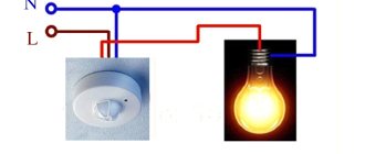
Voltage divider for measuring thermistor resistance
This will be our circuit for interacting with the thermistor. When the thermistor detects a change in temperature, it will be reflected in the output voltage.
Now, as usual, we use the formula for the voltage divider.
\[V_{output}=V_{s}\cdot(\frac{R_{balance}}{R_{thermistor}+R_{balance}})\]
But we are not interested in the output voltage Vout, we are interested in the resistance of the thermistor Rthermistor. So we'll express it:
\[R_{thermistor}=R_{balance}\cdot(\frac{V_s}{V_{output}}-1)\]
This is much better, but we need to measure our output voltage as well as the supply voltage. Since we are using the Arduino's built-in ADC, we can represent the voltage as a numerical value on a specific scale. So, the final form of our equation is shown below:
\[R_{thermistor}=R_{balance}\cdot(\frac{D_{max}}{D_{measured}}-1)\]
This works because no matter how we represent voltage (in volts or digital units), these units cancel out in the numerator and denominator of the fraction, leaving a dimensionless value. We then multiply it by the resistance to get the result in ohms.
Our Dmax will be equal to 1023, since this is the largest number that our 10-bit ADC can produce. Dmeasured is the measured value by the analog-to-digital converter, which can range from zero to 1023.
All! Now you can start assembling!
Characteristics of NTC thermistors
We will describe the main points and tools for determining suitable thermistors.
Ratio t°/Ohm (RT curve)
Most NTC detectors are suitable for the temperature range of −55...+200° C, where they are most accurate. But there is also a special family for temperatures close to abs. zero (−273.15 °C), as well as for values above +200.
The figure shows the general trend; specific numbers depend on the specification and denomination. The curve clearly shows the feature of the NTC type: t° increases, resistance. decreases. In posistors (PTC) it’s the other way around, and they have a nuance: they have a kind of breaking point, at which the resistance greatly changes. at some values, so working with them is more difficult. This is one of the reasons why most not very expensive and relatively simple devices are equipped with STC detectors.
Temperature sensitivity is expressed as % change per 1 degree Celsius. Typical sensitivity values range from −3 to −6% per 1°.
Heat capacity and self-heating
Self-heating occurs when current flows through a thermistor. Since it is a resistor, energy is dissipated in the form of heat, which affects the accuracy of the measurements. The level of this phenomenon depends on the current strength, the environment, as well as on the TKS, the number of parts on the segment. The fact that heating affects the resistance, current carrying capacity of the detector, and depends on environmental conditions makes the part indispensable for use in tanks containing liquid.
Thermal capacity refers to the amount of heat required to increase the temperature of the sensor by 1° C, expressed in mJ/° C. The parameter is extremely important when using a thermal sensor as a limiter for starting relays, since it determines the speed of response of this element.
Sensitivity
Let us characterize sensitivity with an excerpt from a specialized website:
Current-voltage characteristics, operating modes and their application
The selection is also carried out according to the current-voltage characteristic (CVC), which depends on the temperature attached to the device with the STC sensor and on its design.
NTC sensors with a working mark on the descending segment of the current-voltage characteristic are used as relays (starting, temporary) in equipment where the power of electromagnetic radiation of ultra-high frequencies is measured and controlled. And also for heat control systems, fire alarms, in installations that control the flow of liquids and bulk substances.
Brief characteristics of devices
Sensors of this type are compact, highly sensitive elements that are used to maintain specified temperature conditions. Signals are transmitted via compensation cables connected to thermostats, control panels or other devices. The standard wire length for most thermistor models is 1-1.5 m and can be increased if necessary.
NTC temperature sensors are characterized by high speed and a wide range of operating temperatures. The use of modern technologies in their production can significantly reduce the resistance error: as a rule, the tolerance does not exceed 1%.
Where exactly are NTC temperature sensors used?
Let us specify where exactly NTC sensors are used.
The most characteristic areas:
- all possible temperature sensors;
- refrigeration, heating, and heating systems where a decrease in temperature is not allowed;
- ventilation and air conditioning systems;
- control over the degree of cooling in pipes, in open locations;
- heated floors, boilers (water heaters), boilers;
- detection of the absence or presence of liquid;
- current limiters;
- temperature monitoring in cars and other units.
To summarize, these are the following temperature directions:
- measurement;
- control, management related to t°;
- compensation processes.
Examples of practical application:
- various thermostats, thermostats for the environment in refrigerators, boilers, for cable ties, surfaces of heating structures;
- thermometers of various media (liquids, gases), including air in rooms;
- heaters for 3D printing devices (to control working areas so that the material does not stick to them);
- car engines, motors of various types, including electric (preventing overheating);
- ovens (preventing burning, burning of cooked food).
When installing film heated floors, NTC remote sensors are placed in a corrugated pipe, for example, standard Ø 16 mm, directly under one of the IR heating strips in the segment of lowest heat transfer (under rugs, furniture with short legs).
NTC detectors can be divided into 3 groups depending on which electrical characteristics are important for certain purposes.
For what purposes are certain characteristics significant?
| Characteristic | Where is it used? |
| Resistance-temperature | For applications, devices for which the temperature/resistance ratio is significant. These are devices for measuring t°, monitoring, control and compensation, and some other related physical processes. The current on the thermistor is kept as low as possible in order to minimize self-heating of such a probe. |
| Current temporary | Devices with a time delay, limiting inrush currents, preventing overloads, overvoltages and other things. Characteristic related to heat capacity, dissipation of ntc sensor. The circuit relies on a thermistor, heats up due to the current across it, at a certain point changes appear. |
| By voltage | For devices based on the characteristics of voltage, current of thermal resistors. These are devices for monitoring environmental conditions, parameters on the circuit, which initiate changes in the operating level on a given circuit curve. Also for current limitation, temperature compensation, t° measurements. |
Symptoms of a thermistor failure
Thermistors are usually located in the dishwasher tray. Many users wonder: what signs indicate a problem with the temperature sensor? The most common symptoms are a complete lack of heating or, conversely, excessive heating of the water. Regardless of the selected temperature mode, the water can even heat up to a boil.
The temperature of the machine body also increases; when the door is opened, hot steam comes out of it. In this case, the NTC sensor does not work for some reason, so the electronic board does not turn off the heating element in time.
Modern household appliances support the function of automatic diagnosis of breakdowns. For example, in Miele dishwashers, a malfunction of the temperature sensor is indicated by errors F01 and F02 on the display.
Designation on the diagram
On the diagrams, NTC is indicated by a rectangle (empty) crossed out by an oblique line at the bottom with a horizontal leg; there is also a “t°” icon with a minus. PTC posistors have “+”.
Another designation option is a schematic image of a spiral (like the teeth of a cardiogram), crossed out by an oblique line with the same temperature symbol:
Schemes, connection
Schemes are used for homemade products and assemblies. This question, like calculations during selection, is a separate large topic, so we will describe only the basics to orient the reader.
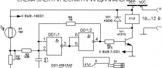
Circuit diagram for ATmega and Arduino (programming will also be required):
The assembly below uses a TH10K thermistor and a 10k ohm resistor as R (balance):
Another diagram:
Checking and replacing NTC temperature sensors
The installation itself is elementary - the sensor is plugged into the mounting socket, the cores of its cable are connected to the terminals, and the wires can also be connected by twisting, soldering, or crimping. Typically, the power wiring goes to the thermostat or thermostat board.
Below in the photo is a replacement sensor for measuring the temperature in a room with a 5-meter cable for a heating boiler. Control and adjustment are carried out by a thermostat; it can be included with the unit or purchased separately.
Breakdowns, diagnostics, repairs
NTC sensors usually break down due to environmental influences, for example, in boilers, scale gets stuck on them, and coolant gets inside.
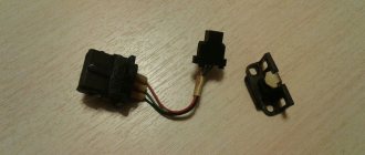
The test consists of measuring the resistance with a multimeter at a certain temperature and comparing the result with the specification. In our case, the 2 tested sensors in the photo below are working, R is about 10 kOhm, which corresponds to approximately +25° C (the temperature of the room where the products are located).
The sensor was placed on a metal weight for cooling, we see that the resistance. as the temperature decreases, it increases (the indicator in the photo corresponds to about +21). In the second photo, the sensor was removed from cooling - R drops with increasing t°.
So, to check you will need a thermometer, a multimeter and a temperature dependence table, which can be downloaded online for specific sensor models for the existing brand of boiler, refrigerator, etc., example (right column - Ohms, left - °C):
Types of failure symptoms:
- if there is no resistance on the sensor, this means a break;
- if R differs greatly from the specification - internal failure of the thermistor itself;
- resistance corresponds to temperature, but in some interval the detector begins to lie or stops measuring altogether. Then the boiler also goes into emergency mode.
Signs of a broken element on the boiler (similar to all household appliances):
- immediately (several seconds) after turning on and activating the pump, it goes into emergency mode;
- after resetting the error, everything repeats;
- after opening the hot water tap, the boiler gives an error. Most likely, the sensor on the warm liquid pipe is broken;
- sudden stop;
- discrepancy between the output temperature and the configured values, the device can constantly heat up (until the limitation, protection against overheating is triggered);
- jumps in temperature or no heating/cooling at all.
The NTC sensor, and especially its thermistor, cannot be repaired - it must be replaced with a similar one. The exception is when the contacts have become sour, scale has appeared, and this is the cause of the breakdown, then the legs of the elements are cleaned.
For appliances and equipment (refrigerators, washing machines, boilers, cars), such products are sold in specialty stores and service centers.
It is advisable to have a known good part in stock in order to carry out diagnostics with 100% accuracy. You just need to connect a new thermistor and see how the unit works.
Almost always, when the boiler, boiler, or floor turns on, that is, the electrical system itself is working, but oddities and incorrect operation related to temperature are observed, the reason being the temperature sensor. It is checked first, especially since the procedure is simple. There are also devices with self-diagnosis - they display an error code on the display, LEDs, and sound, then it is even easier to determine whether the sensor is faulty.
Possible next steps
Everything in this article shows a fairly simple way to measure temperature using a cheap thermistor. There are a couple more ways to improve the scheme:
- add a small capacitor in parallel with the divider output. This will stabilize the voltage and may even eliminate the need to average a large number of samples (as was done in the code) - or at least we will be able to average fewer samples;
- Use precision resistors (less than 1% tolerance) to get more predictable measurements. If measurement accuracy is critical to you, keep in mind that self-heating of the thermistor may affect the measurements; Self-heating is not compensated for in this article.
Of course, thermistors are only one of the sensors used to measure temperature. Another popular choice is sensor chips (an example of working with one of them is described here). This way you won't have to deal with linearization and complex equations. The other two options are thermocouple and infrared sensor type; the latter can measure temperature without physical contact, but it is no longer as cheap.
I hope the article was useful. Leave comments!
Original article:
- Joseph Corleto. Measuring Temperature with an NTC Thermistor