On the blog we have already looked at various ignition systems, in particular contactless ones, in which the mechanical breaker in the distributor is replaced by a tricky sensor. Let's talk about it, about the Hall sensor, that's what they call it. The Hall sensor, its operating principle is that it provides a cutoff at the desired point for igniting the working mixture in the cylinder, but let's take it in order.
[contents]
What is a Hall sensor in a car
A hall sensor is a small device that operates on an electromagnetic principle. Even old cars from the Soviet automobile industry have these sensors - they control the operation of the gasoline engine. If malfunctions appear in the device, the engine will, at best, lose stability.
They are used to operate the ignition system, phase distribution in the gas distribution mechanism and others. To understand what malfunctions relate to sensor failure, you should understand its structure and operating principle.
How large electrical loads can be controlled using Hall sensors
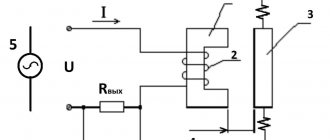
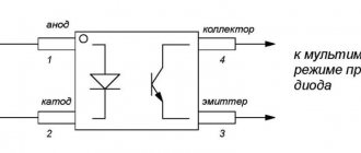
We already know that the output power of the Hall sensor is very small (10 to 20 mA). Therefore, it cannot directly control large electrical loads. However, we can control large electrical loads using Hall effect sensors by adding an open collector NPN transistor (current drain) to the output.
The NPN (current sink) transistor functions in the saturated state as a sink switch. It closes the output contact to ground when the flux density exceeds the preset ON value.
The output switching transistor can be in different configurations such as open emitter transistor, open collector transistor, or both. This is how it provides a push-pull output that allows it to draw enough current to drive large loads directly.
Where is it located and what does it look like?
The Hall effect has found application in many car systems, such as:
- Determines the position of the crankshaft (when the piston of the first cylinder is at the top dead center of the compression stroke);
- Determines the position of the camshaft (to synchronize the opening of valves in the gas distribution mechanism in some models of modern internal combustion engines);
- In the ignition system breaker (on the distributor);
- In the tachometer.
During the rotation of the motor shaft, the sensor reacts to the size of the teeth slots, which generates a low voltage current that is supplied to the switching device. Once in the ignition coil, the signal is converted into high voltage, which is necessary to create a spark in the cylinder. If the crankshaft position sensor is faulty, the engine cannot be started.
A similar sensor is located in the contactless ignition system breaker. When it fires, the windings of the ignition coil switch, allowing it to produce a charge on the primary winding and discharge to the secondary.
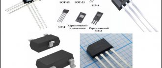
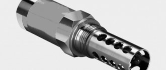
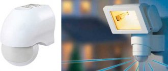
The photo below shows what the sensor looks like and where it is installed in some cars.
In the distributor
Crankshaft sensor
Camshaft sensor
Tachometer sensor
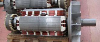
Hall sensor in the electric motor
DIY repair and replacement
If structural elements are damaged, the sensor cannot be repaired. The car owner needs to exchange the part for the original sensor or find an analogue in reference books or catalogs. The algorithm for installing a new sensor depends on the design features of the car. To perform the work, you need a set of plumbing tools (wrenches and screwdrivers). The procedure takes 10–20 minutes.
To replace a faulty camshaft position sensor, you must (using the example of a Lada Priora with a 16-valve engine):
- Find the sensor installation point using the electrical diagram or wiring harness connected to the front engine cover near the crankshaft pulley.
- Remove the wiring block and unscrew the 2 bolts, and then carefully remove the sensor from the mounting socket.
- Inspect the product. If there are traces of mechanical impact on the body, remove the plastic casing and check the condition of the gas distribution mechanism. Otherwise, install a new sensor, tighten the mounting bolts and connect the signal cable. When installing, make sure there is a rubber seal.
A number of car manufacturers recommend replacing the Hall sensor after 100–150 thousand kilometers.
Such requirements are determined by harsh operating conditions (units operate under conditions of temperature changes and are subject to vibration loads). Heating and cooling cycles negatively affect semiconductors and can destroy the plastic case. Water or condensation penetrates into cracks and accelerates sensor failure.
To replace the sensor, you need to find the sensor installation point.
To replace the sensor in the distributor:
- Unfasten the latches and remove the cover.
- Place marks on the crankshaft pulley and timing gear.
- Unscrew the mounting bolts and remove the ignition distributor for further disassembly.
- Remove the faulty sensor and inspect and service the structural elements.
- Install the new sensor and reassemble in reverse order.
- Check engine performance and adjust the ignition (if necessary).
Device
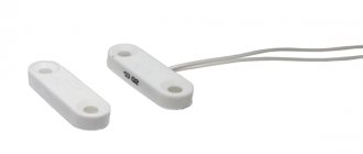
The device of a simple hall sensor consists of:
- Permanent magnet. It creates a magnetic field that acts on the semiconductor, in which a low voltage current is created;
- Magnetic cores. This element perceives the action of the magnetic field and generates current;
- Rotating rotor. This is a curved metal plate that has slots. When the shaft of the main device rotates, the rotor blades alternately block the influence of the magnet on the rod, which creates impulses inside it;
- Plastic housings.
What is the Hall effect and how can it be used in technology?
The magnetic field is widely used in automotive technology, despite its invisibility and intangibility.
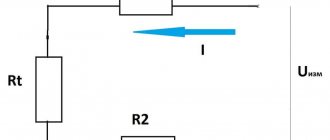
Even light, which consists of electric and magnetic fields, is perceived due to its electrical component. However, with the help of special magnetically sensitive sensors, the field can be recorded and even measured. One of these sensors is based on the Hall effect, which consists in the appearance of a transverse potential difference on a semiconductor crystal along which current flows. It is formed only when the crystal is placed in a magnetic field; everything else does not polarize the doped silicon wafer. This voltage is subject to recording, meaning that the sensor is within the range of the magnetic field.
Actually, all this is not enough to use the crystal as a sensor. The magnetic field is present everywhere, it is necessary to determine its excess over the natural background and interference. To do this, a weak signal amplifier and an adjustable threshold element (comparator) are connected to the plate. The entire circuit outputs a logical “0” at the electrical level if there is a field, and a logical one in all other cases. This kind of negative logic is commonly accepted in digital technology. And so that at the moment of a signal change there is no “bumpiness” of the output due to uncertainty, the device is equipped with a Schmitt trigger. This is a circuit that provides an amplitude response delay (hysteresis), protecting against digital bounce and interference at the moment of switching, guaranteeing a single steep edge of the signal and unambiguous timing.
Types and scope of application
All Hall sensors are divided into two categories. The first category is digital, and the second is analog. These devices are successfully used in various industries, including the automotive industry. The simplest example of this sensor is DPKV (measures the position of the crankshaft as it rotates).
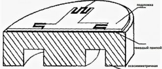
Analog Hall Sensor Element
In other industries, similar devices are used, for example, in washing machines (weighing laundry based on the rotation speed of a full drum). Another common application of such devices is in a computer keyboard (small magnets are located on the back of the keys, and the sensor itself is installed under an elastic polymer material).
Professional electricians, when measuring the current strength in a cable without contact, use a special device that also contains a Hall sensor, which reacts to the strength of the magnetic field created by the wires and produces a value corresponding to the strength of the magnetic vortex.