How to check a 1 phase motor?
The scheme for checking it looks like this:
- Turn on the device in Ohm units and measure the resistance of the collector lamellas in pairs.
- Then measure the resistance between the armature housing and the commutator.
- Check the stator windings.
- Measure the resistance between the housing and the stator terminals.
Interesting materials:
How to remove excess spice from a dish? How to remove marker from wallpaper? How to stop LED lamps from flickering? How to remove scale from a boiler? How to remove a sagging chin at home? How to remove the heat from pepper in soup? How to remove spice from soup? How to remove advertising in contact on your phone? How to stop a strong appetite? How to remove ballpoint pen marks from skin?
Device and principle of operation
A megohmmeter is a device for checking insulation resistance. There are two types of devices - electronic and pointer. Regardless of the type, any megohmmeter consists of:
- Constant voltage source.
- Current meter.
- Digital screen or measurement scale.
- Probes, through which voltage from the device is transmitted to the object being measured.
This is what a pointer megaohmmeter looks like (on the left) and an electronic one (on the right)
In pointer instruments, the voltage is generated by a dynamo built into the housing. It is driven by a meter - it rotates the handle of the device with a certain frequency (2 revolutions per second). Electronic models take power from the mains, but can also run on batteries.
The operation of the megohmmeter is based on Ohm's law: I=U/R. The device measures the current that flows between two connected objects (two cable cores, core-ground, etc.). Measurements are made with a calibrated voltage, the value of which is known; knowing the current and voltage, you can find the resistance: R=U/I, which is what the device does.
Approximate diagram of a magaohmmeter
Before testing, the probes are installed in the appropriate sockets on the device, and then connected to the object being measured. During testing, a high voltage is generated in the device, which is transmitted to the object being tested using probes. Measurement results are displayed in mega ohms (MΩ) on a scale or screen.
Tell me why electric motors are made of cast iron and aluminum? what difference does it make? Why can't they be made of steel, for example?
The cast iron body is stronger, much more resistant to mechanical wear, easy to cast and process. Also When working el. the engine generates heat, that is, it heats up and this heat must be released into the atmosphere, and cast iron and aluminum alloy are very good heat exchangers (the batteries in the apartment are cast iron or aluminum alloy)
Tell me, I measured the resistance on the motor windings when it was very hot, it just had one turn burnt off from the terminal block, everything showed normal and I didn’t sew it on the body, but only the motor cooled down, the instruments showed me that this motor was faulty. Why is that??
Cable insulation resistance measurement
It is often necessary to measure the insulation resistance of a cable or wire. If you know how to use a megohmmeter, when checking a single-core cable it will take no more than a minute; with multi-core cables you will have to tinker longer. The exact time depends on the number of wires - you will have to check each one.
Select the test voltage depending on the network voltage with which the wire will operate. If you plan to use it for 250 or 380 V wiring, you can set it to 1000 V (see table).
Checking a three-core cable - you don’t have to twist it, but try on all pairs
To check the insulation resistance of a single-core cable, we attach one probe to the core, the second to the armor, and apply voltage. If there is no armor, attach the second probe to the “ground” terminal and also apply test voltage. Let's look at the readings. If the arrow shows more than 0.5 MOhm, everything is normal and the wire can be used. If it is less, the insulation is broken and it cannot be used.
You can check the multi-core cable. Testing is carried out for each core separately. In this case, all other conductors are twisted into one bundle. If at the same time it is necessary to check the ground fault, a wire connected to the corresponding bus is added to the common harness.
If the cable has a screen, metal sheath or armor, these are also added to the bundle. When forming a tourniquet, it is important to ensure good contact.
The insulation resistance of socket groups is measured in approximately the same way. All devices are turned off from the sockets and the power to the panel is turned off. One probe is installed on the ground terminal, the second - in one of the phases. Test voltage - 1000 V (according to the table). Turn it on and check it. If the measured resistance is greater than 0.5 MΩ, the wiring is normal. We repeat with the second core.
If the wiring is old - there is only phase and zero, testing is carried out between two conductors. The parameters are similar.
Checking the motor windings. Malfunctions and test methods
Ideally, in order to check the windings of an electric motor, it is necessary to have special instruments designed for this, which cost a lot of money.
Surely not everyone has them in their home. Therefore, it is easier for such purposes to learn how to use a tester, which has another name: a multimeter. Almost every self-respecting home owner has such a device. Electric motors are manufactured in various versions and modifications, and their malfunctions are also very different. Of course, not every fault can be diagnosed with a simple multimeter, but most often checking the motor windings with such a simple device is quite possible.
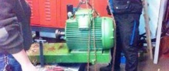
Any type of repair always begins with an inspection of the device: the presence of moisture, whether parts are broken, the presence of a burning smell from the insulation and other obvious signs of malfunction. Most often, the burnt winding is visible. Then no checks and measurements are needed. Such equipment is immediately sent for repair. But there are times when there are no external signs of failure, and a thorough check of the motor windings is required.
Types of windings
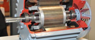
If you don’t go into details, the motor winding can be imagined as a piece of conductor that is wound in a certain way in the motor housing, and it seems that nothing should break in it.
However, the situation is much more complicated, since the electric motor winding has its own characteristics:
- The material of the winding wire must be uniform along its entire length.
- The shape and cross-sectional area of the wire must have a certain accuracy.
- In industrial conditions, a layer of insulation in the form of varnish must be applied to the wire intended for winding, which must have certain properties: strength, elasticity, good dielectric properties, etc.
- The winding wire must provide strong contact when connected.
If there is any violation of these requirements, then the electric current will flow under completely different conditions, and the electric motor will deteriorate its performance, that is, the power, speed will decrease, and may not work at all.
Checking the motor windings of a 3-phase motor . First of all, disconnect it from the circuit. The majority of existing electric motors have windings connected in star or delta configurations.
The ends of these windings are usually connected to blocks with terminals that have the appropriate markings: “K” - end, “N” - beginning. There are options for internal connections, the nodes are located inside the motor housing, and different markings (numbers) are used on the terminals.
The stator of a 3-phase electric motor uses windings that have equal characteristics and properties, and the same resistance. When measuring the winding resistances with a multimeter, it may turn out that they have different values. This already makes it possible to assume that there is a malfunction in the electric motor.
Possible faults
It is not always possible to visually determine the condition of the windings, since access to them is limited by the design features of the engine. In practice, you can check the winding of an electric motor using its electrical characteristics, since all motor breakdowns are mainly detected:
- A break, when the wire is broken or burnt out, no current will pass through it.
- A short circuit caused by damaged insulation between the input and output turns.
- A short circuit between turns, with the insulation damaged between adjacent turns. As a result, damaged turns are self-excluded from operation. Electric current flows through the winding, which does not involve damaged turns that do not work.
- By breaking through the insulation between the stator housing and the winding.
Methods
Checking the motor windings for open circuits
This is the simplest type of verification. The malfunction is diagnosed by simply measuring the wire resistance value. If the multimeter shows very high resistance, then this means that there is a wire break with the formation of air space.
Checking the motor windings for short circuits
If there is a short circuit in the motor, its power will be cut off by the installed short circuit protection. This happens in a very short time. However, even in such a short period of time, a visible defect in the winding may occur in the form of carbon deposits and metal melting.
If you measure the winding resistance with instruments, you get a small value that approaches zero, since a piece of the winding is excluded from the measurement due to a short circuit.
Checking the motor windings for interturn short circuits
This is the most difficult task in identifying and troubleshooting. To check the motor winding, several measurement and diagnostic methods are used.
Checking the motor windings using an ohmmeter
This device operates on direct current and measures active resistance. During operation, the winding forms, in addition to active resistance, a significant inductive resistance value.
If one turn is closed, then the active resistance will practically not change, and it is difficult to determine it with an ohmmeter. Of course, you can accurately calibrate the device, carefully measure all windings for resistance, and compare them. However, even in this case it is very difficult to detect shorted turns.
The results are much more accurately produced by the bridge method, which measures active resistance. This method is used in a laboratory environment, so ordinary electricians do not use it.
Current measurement in each phase
The phase current ratio will change; if a short circuit occurs between the turns, the stator will heat up. If the engine is fully operational, then the current consumption is the same in all phases. Therefore, by measuring these currents under load, we can confidently say about the actual technical condition of the electric motor.
Checking motor windings with alternating current
It is not always possible to measure the total winding resistance and take into account the inductive reactance. For a faulty motor, you can check the winding with alternating current. For this, an ammeter, a voltmeter and a step-down transformer are used. To limit the current, a resistor or rheostat is inserted into the circuit.
To check the motor winding, a low voltage is applied and the current value is checked, which should not be higher than the nominal value. The measured voltage drop across the winding is divided by the current to obtain the total resistance. Its value is compared with other windings.
The same circuit makes it possible to determine the current-voltage properties of the windings. To do this, you need to take measurements at various current values, then write them down in a table or draw a graph. There should not be large deviations when comparing with other windings. Otherwise, there is an interturn short circuit.
Checking the motor windings with a ball
This method is based on the formation of an electromagnetic field with a rotating effect if the windings are in good condition. They are connected to a symmetrical voltage with three phases, low value. For such tests, three step-down transformers with the same data are used. They are connected separately for each phase.
To limit the load, the experiment is carried out in a short period of time.
Voltage is applied to the stator windings, and a small steel ball is immediately introduced into the magnetic field. When the windings are in good condition, the ball rotates synchronously inside the magnetic circuit.
If there is a short circuit between the turns in any winding, the ball will immediately stop where there is a short circuit. When carrying out the test, the current must not be allowed to exceed the rated value, since the ball can fly out of the stator at high speed, which is dangerous for humans.
Determining the polarity of windings using the electrical method
The stator windings have terminal markings, which sometimes may not be there for various reasons. This creates difficulties during assembly.
To determine the marking, several methods are used:
- A weak DC source and an ammeter.
- Step-down transformer and voltmeter.
The stator acts as a magnetic circuit with windings operating on the principle of a transformer.
Reasons for low resistance
There are several reasons for low insulation resistance.
Electric machine overheating
This situation occurs due to an overload of the electric machine or a break in one of the phases in three-phase electric motors. It is impossible to eliminate this problem in a workshop and the device must be sent to a specialized enterprise to replace the windings.
Protection devices help prevent such a malfunction:
- The thermal relay turns off the electric machine when overloaded;
- The voltage relay turns off the installation if one of the phases is missing or the network voltage is low.
Important! For better protection, temperature sensors are built inside electric motors. In new machines they are installed during manufacture, and in old machines such devices can be installed during planned or major repairs.
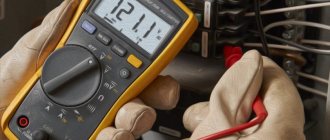
Working with a megohmmeter
During testing, the megohmmeter produces a very high voltage - 500 V, 1000 V, 2500 V. In this regard, measurements must be taken very carefully. At enterprises, persons with an electrical safety group of at least 3 are allowed to work with the device.
Before taking measurements with a megohmmeter, the circuits under test are disconnected from the power supply. If you are going to check the condition of the wiring in a house or apartment, you need to turn off the switches on the panel or unscrew the plugs. Then turn off all semiconductor devices.
One of the options for modern megaohmmeters
If you check the socket groups, remove the plugs of all devices that are included in them. If the lighting circuits are checked, the light bulbs are unscrewed. They will not withstand the test voltage. When checking the insulation of the motors, they are also completely disconnected from the power supply. After this, grounding is connected to the circuits being tested. To do this, a stranded wire in a sheath with a cross-section of at least 1.5 mm2 is attached to the “ground” bus. This is the so-called portable grounding. For safer operation, the free end with the exposed conductor is attached to a dry wooden holder. But the bare end of the wire must be accessible so that it can touch wires and cables.
Requirements for ensuring safe working conditions
Even if you want to measure the cable insulation resistance at home, before using a megohmmeter you should familiarize yourself with the safety requirements. There are several basic rules:
- Hold the probes only by the insulated part limited by stops.
- Before connecting the device, turn off the voltage and make sure that there are no people nearby (along the entire route being measured, if we are talking about cables).
How to use a megohmmeter: electrical safety rules
The rules are not very complicated, but your safety depends on their implementation.
How to connect probes
The device usually has three sockets for connecting probes. They are located at the top of the instruments and are labeled:
There are also three probes, one of which has two tips on one side. It is used when it is necessary to exclude leakage currents and clings to the cable screen (if there is one). There is an “E” on the double tap of this probe. The plug that comes from this outlet and is installed in the corresponding socket. Its second plug is installed in the “L” socket - line. A single probe is always connected to the ground socket.
Probes for megaohmmeter
There are stops on the probes. When taking measurements, grasp them with your hands so that your fingers reach these stops. This is a prerequisite for safe operation (remember about high voltage).
If you only need to check the insulation resistance without a screen, place two single probes - one in the “Z” terminal, the other in the “L” terminal. Using crocodile clips at the ends, we connect the probes:
- To the wires being tested, if you need to check the breakdown between the wires in the cable.
- To the core and the “ground”, if we check the “breakdown to ground”.
There is a letter “E” - this end is inserted into a socket with the same letter
There are no other combinations. The insulation and its breakdown are checked more often; working with the screen is quite rare, since shielded cables themselves are rarely used in apartments and private houses. Actually, using a megohmmeter is not particularly difficult. It is only important not to forget about the presence of high voltage and the need to remove the residual charge after each measurement. This is done by touching the ground wire to the wire you just measured. For safety, this wire can be secured to a dry wooden holder.
Check the insulation resistance of the electric motor
To carry out measurements, the engine is disconnected from power. It is necessary to get to the winding terminals. Asynchronous motors operating at voltages up to 1000 V are tested with a voltage of 500 V.
To check their insulation, we connect one probe to the motor housing, and apply the second one to each of the terminals in turn. You can also check the integrity of the connection between the windings. For this check, probes must be installed on pairs of windings.
We are looking at an insulation resistance measuring device called a Megger. The purpose of this device is to test the resistance of the windings of devices such as an electric motor, using a sufficiently high voltage. You see three setting limits for the measurement: 250 volts, 500 volts and 1000 volts. We need voltages that high so that we can detect certain types of faults. I'm going to show this using a 5kW motor. This is a faulty motor, it was removed during maintenance because it has a ground fault in one of the windings. I'll show you how to check this using a megger. First I'm going to take the megger's ground clamp and attach it to the motor housing. Next, right here we look at the three-phase windings at the output of the motor junction box. I have a blue, orange and white wire and I'm going to measure the resistance with my meter for the insulation resistance between those phases and ground. When carrying out measurements, we observe safety precautions, because during operation the megger produces high voltage. I will connect the measuring probe of the device and the bare end of the phase wire, the probe must be held with only one hand by the insulated part. To start the megohmmeter, press the orange button. So, let's take measurements. Having pressed the button, we see that the arrow has swung all the way to the right. Since the device is in the orange measurement range, we will read the readings at the top of the scale, and the arrow on the right side of the scale means zero ohm value. This is a malfunction, we should not have zero ohms. There must be a very high resistance between the phase winding and the housing. I'll do this again on another phase of the winding, I'll attach the probe to it and press the button - you can see that it also shows zero. And, of course, the last winding will have the same readings. I say - of course, because it does not matter which winding is shorted to the housing. This measurement can be made at any terminal of the phase winding, since they are connected together inside the motor, and a breakdown anywhere on the winding will give the same insulation resistance reading to the frame. Now, to prove to you that high voltage really matters and makes a difference to our measurements, I will switch the device to the low voltage range. In green mode, the device works like a regular ohm meter. And like a regular ohm meter, it uses very low voltage to test resistance. To show you how this works, I will attach the ground clamp to the motor housing and you will see that the needle remains on the left side of the scale, because on the green scale, “right” is infinity, and “left” is zero. So, with a “short circuit” the arrow will be on the left side of the scale and with a “break” - the arrow will be on the right side of the scale at this low value of the set voltage. With this in mind, I reconnect the probe to the phase winding. and click the “Check” button. Please note that the arrow has gone to the right, we remember that this means “break”, and this indicates that the winding is good. Just to make sure, when I disconnect the probe and press the button again, the arrow stays to the right, the meter reads "open". In other words, a short circuit to frame is not detected in low voltage mode, but can be detected in high voltage mode. I'll attach the probe again - just to prove that it works, the probe is attached - I press the button, the arrow turns to the right, which means zero ohms or low resistance. In high voltage mode, I will remove the probe to see what happens - the arrow moves to the left, which means "high resistance". So, I can clearly see that there is a fault in this motor when using high voltage, but I don't see any fault when using low voltage. And this is precisely the unique value of an insulation resistance meter called a megohmmeter. _
Double winding transformers
The insulation resistance of the transformer windings is measured with a megohmmeter for a voltage of 2500 V with an upper measurement limit of not less than 10,000 MOhm. Measurement in two-winding transformers is carried out alternately for the high and low voltage windings relative to the housing with the remaining windings disconnected and grounded to the housing and between windings of different voltages (Figure 2).
The figure shows circuits for measuring the insulation resistance of power two-winding transformers for the following cases:
a) between the primary winding and the housing;
b) between the secondary winding and the housing;
c) between the primary and secondary windings.
When measuring insulation resistance, all accessible terminals of the tested windings should be connected to each other, and the transformer tank should be reliably grounded through a special grounding bolt.
The normalized insulation resistance of the transformer windings is given in Table 1.
Table 1 - Lowest permissible insulation resistance
R 60
Rated voltage of the high voltage winding, kV
R60 value, MOhm, at winding temperature, 0 C
Using a multimeter and several devices, without particularly understanding the principle of operation of electric motors, you can check:
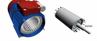
- An asynchronous three-phase squirrel-cage motor is the easiest to test, due to its simple internal structure, due to which this type of electric motor is most popular;
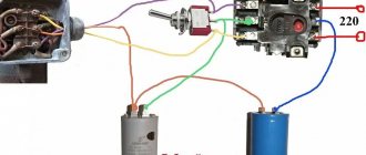
- Asynchronous single-phase (two-phase, capacitor) electric motor with a squirrel-cage rotor - often used in various household appliances connected to a 220 V network (washing machines, vacuum cleaners, fans).
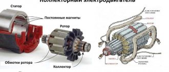
- DC commutator motor – widely used in cars as a drive for windshield wipers (windshield wipers), window lifts, pumps, fans;
- AC commutator motor – used in hand-held electric tools (drills, rotary hammers, grinders, etc.)
- An asynchronous motor with a wound rotor - in comparison with an electric motor with a squirrel cage rotor, has a powerful starting torque, therefore it is used as a drive for power equipment - hoists, elevators, cranes, machine tools.