U = E – IRin
If there are no requirements for high accuracy of EMF measurement, then to reduce the current you can use a voltmeter with a high internal resistance, for example an electronic one. In this case, we can assume that the measured voltage is U ~ E. More accurate methods for measuring EMF are associated with the use of compensation circuits (Fig. 2).
Rice. 2. EMF measurement circuits
In them, the voltage measured by a voltmeter PV, taken from a variable resistor R, is compared with the voltage at the EMF source.
By changing the voltage at the output of a variable resistor (potentiometer), it is possible to achieve a condition where the measuring device P shows the absence of current through the EMF source. In this case, the voltmeter readings will exactly correspond to the value of the source emf, i.e. U = E.
Current measurement
You can measure the current directly with an ammeter connected to the open circuit of the measured circuit (Fig. 3, a).
Rice. 3. Current measurement circuits
If it is necessary to expand the measurement limits of the ammeter, it is necessary to connect a resistor in parallel with the ammeter (Fig. 3, b), which is most often called a shunt . Then only part of the current will pass through the ammeter, and the rest through the shunt. Since the resistance of ammeters is usually small, to significantly expand the measurement limits, the shunt resistance must be very small. There are formulas for calculating the shunt resistance, but usually in practice you have to manually adjust its resistance by monitoring the current with a reference ammeter.
To measure large alternating currents, measuring current transformers are often used (Fig. 3, c). Their primary winding, included in the break of the measured circuit, has a number of turns W1 less than the number of turns W2 of the secondary winding, i.e. the transformer is step-up in voltage, but it is step-down in current. The ammeter is connected to the output of the secondary winding of the current transformer. Often laboratory current transformers do not have a pre-made primary winding at all, and their housing has a wide through hole through which the experimenter himself winds the required number of turns (Fig. 3, d). Knowing the number of turns of the secondary winding (it is usually indicated on the body of the current transformer), you can select the transformation ratio n = W1/W2 and determine the measured current Ix from the readings of the ammeter Ipr using the following formula:
Iх = Ipr/n
A completely different way is used to measure currents in electronic circuits, which are usually soldered and manufactured on printed circuit boards; It is almost impossible to make any rupture in them. To measure currents in these cases, voltmeters are used (usually electronic ones with high internal resistance to eliminate the influence of the device on the operation of the electronic circuit), connecting them to circuit resistors, the values of which are either known or can be pre-measured. Using Ohm's law, you can determine the current strength:
I = U/R
The essence of the phenomenon
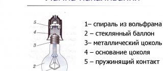
Voltage is the electrical driving force that is designed to push free types of electrons from one atom to another in a certain direction. A mandatory requirement for the flow of charges is the presence of a circuit with a closed loop, which creates the conditions for them to move. If there is a break in the electrical circuit, then the process of directional movement of particles stops.
Note! It is worth noting that the unit of voltage in an electrical circuit depends on the material of the conductor, how the load is connected, and what the temperature is.
What it is
Resistance measurement
Often, when working with electrical installations or when adjusting electronic circuits, it is necessary to measure various resistances. The simplest way to measure resistance is to use two measuring instruments: an ammeter and a voltmeter. With their help, they measure the voltage and current in the resistance R connected to the power source, and according to Ohm’s law, find the value of the desired resistance:
R = U/I
However, this method of measuring resistance does not allow obtaining measurement results with high accuracy, since the measurement results are influenced by the own internal resistances of the ammeter and voltmeter. So, in the one shown in Fig. 4, in the circuit, the ammeter measures not only the current passing through the resistance, but also the current passing through the voltmeter, which introduces a methodological measurement error.
Rice. 4. Circuit for measuring resistance using the ammeter and voltmeter method (a) and ohmmeter circuit (b)
Measurements are usually made in this way in cases where there are no special instruments - ohmmeters. One of the possible ohmmeter circuits (Fig. 4, b) is sequential. It consists of an autonomous power source E, a variable resistor R and a magnetoelectric milliammeter RA. Dry cells or batteries with a voltage of 1.4...4.5 V are usually used as a power source. If a resistance Rx, the value of which must be determined, is connected to the terminals of the device, then a current will flow through the circuit, the value of which will depend on the value of the resistance. Since the milliammeter measures this current, its scale can be directly graduated in ohms. The scale of such an ohmmeter is reversed, i.e. zero is on the right side of the scale, since when the input resistance is zero (short circuit mode), the maximum current will flow through the ammeter. If the external circuit is open, which corresponds to an infinitely high input resistance, then the milliammeter needle will be at the very left of the scale, where the x sign is. The scale of such an ohmmeter is sharply nonlinear, which to some extent makes it difficult to read the results. The variable resistor of the ohmmeter is used to set the device to zero before starting to work with it. To do this, short-circuit the ohmmeter leads and, by rotating the variable resistor knob, achieve zero readings on the device. Since the EMF of the battery decreases over time due to the discharge, this zero setting must be periodically monitored. Using such ohmmeters, you can measure resistance from a few ohms to hundreds of kilo-ohms.
Rice. 5. Schemes of a megometer (a) and an electrical bridge (b)
Measurement of high resistances up to 100 MΩ is usually carried out using megometers (Fig. 5, a). In its classic form, it is a combination of an autonomous power source and a measuring device - a ratiometer. A logometer is a type of magnetoelectric device, which instead of one frame has two, rigidly connected to each other at a certain angle. Just like in a conventional magnetoelectric device, the needle of the device is connected to them and they are located in the magnetic field of a permanent magnet. When current is passed through the windings of the frames, they create torques of opposite signs, as a result of which the position of the arrow will depend on the ratio of the currents in the frames. A resistor R is included in the circuit of one of the frames, and a resistance Rx is included in the circuit of the other, the value of which must be determined. The use of a ratiometer is explained by the fact that its readings are determined only by the ratio of currents within the frame and do not depend on changes in the supply voltage Upit. As a voltage source for the megometer, either an inductor driven by the operator’s hand or a rechargeable battery with an electronic voltage converter is used. Such a power system is determined by the fact that the operation of the device requires high voltages - about 500 V, since at lower voltages the currents in the windings of the device would be too small for its normal operation. The use of an autonomous power source is dictated by the fact that the insulation resistance of cables is often measured with a megometer; in this case, naturally, the voltage in them is turned off. In addition, it is often used to take measurements outdoors where there is no electrical network.
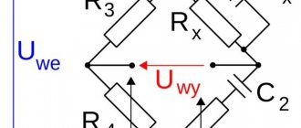
Measurement of small resistances (less than 1 ohm), as well as measurements of other resistances in a wide range of values, can be carried out with high accuracy using electrical bridges.
The electric bridge (Fig. 5, b) consists of four resistances (one of them, Rx, is to be measured), connected in a ring circuit. Each of the resistances forms a bridge arm. A constant supply voltage Upit is supplied to one diagonal of the bridge, and a measuring device is connected to the other - galvanometer R. It is a highly sensitive magnetoelectric device with zero in the middle of the scale. Its purpose is to record the moment when there is no current. Devices of this type are often called null indicators. One or two resistances in the bridge arms are made variable, and it is they that achieve zero readings on the device. The bridge is considered balanced. As the theory of electric bridges shows, the balance condition is achieved when the product of the resistances of the opposite arms is equal, i.e., under the condition R1Rx = R2R3. Therefore, after balancing the bridge, it is possible, knowing the values of all resistances, to determine the value of the unknown resistance
where N = R2/R1 is the multiplier.
The measurement accuracy using DC bridges can be very high. The resulting resistance values may have more than five significant figures. At the same time, the bridge does not allow for quick measurements, since the balancing process requires a certain amount of time and operator skill.
What is a multimeter?
A multimeter is a universal combined measuring device that combines the functions of several measuring devices, that is, it measures almost all indicators of the circuit. The smallest set of functions of a multimeter is a voltage, charge and resistance meter. However, modern manufacturers do not stop there, but instead add a number of functions, such as capacitive measurement of capacitors, current frequency, diode testing (measurement of voltage drop across a pn junction), sound sensors, temperature measurements and measurement of certain transistor parameters, built-in low-voltage generator frequencies and much more.
The multimeter can be:
- Analog. This type of device contains an indicator that has several scales (one for each type of measurement). Analog testers have a number of disadvantages, first of all they are large errors and measurement errors. The design of many models includes a special adjustable resistor, which, when properly configured, somewhat improves the operation of the device, increasing the accuracy of the results. But now digital models have become more widespread.
- Digital. The only external difference between a digital device and an analog device is the screen that numerically represents the measured parameters. Older models are equipped with an LED display, newer versions are equipped with an LCD screen. The disadvantage of these devices is that they are expensive: their price is several times higher than the cost of an analog tester.
Capacitance measurement
Determining the capacitance of a capacitor or other capacitive devices can also be carried out in various ways. The simplest of them is the ammeter-voltmeter method (Fig. 6, a).
Rice. 6. Capacitance measurement circuits
It is in many ways similar to the same method of measuring resistance, with the only difference being that the circuit is powered by an alternating sinusoidal voltage from a low or high frequency generator (or from the network). The capacitance of a capacitor is determined by the following formula:
where f is the frequency of the alternating voltage.
Capacitance is found according to Ohm's law according to instrument readings
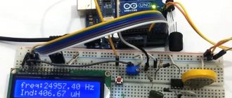
It is more convenient to measure small capacitances using the resonance method (Fig. 6, b). The measured capacitor Cx is connected to a known inductance L, forming an oscillating circuit. The circuit is supplied with sinusoidal voltage from the generator. Using an electronic voltmeter, the voltage on the circuit is measured. At resonance it reaches its maximum.
It is known that the resonant frequency of the circuit can be expressed by the following formula:
Consequently, with a known value of inductance in the circuit and a resonance frequency determined from the maximum readings of a voltmeter, the desired value of capacitance Cx can be found.
The easiest way to measure large capacitances (for example, electrolytic capacitors) is to discharge the capacitor to a known resistance R. It is known that in a time equal to the time constant of the capacitor discharge circuit, its voltage decreases by e times, where e = 2.71 ... is the base of the natural logarithm The time constant of the capacitor discharge circuit to the resistor is determined by the relation
The circuit for measuring capacitance using this method (Fig. 6, c) consists of a constant supply voltage source, known by the value of the resistor R, an electronic voltmeter PV, a switch S and terminals for connecting a capacitor. Using the switch S, the capacitor Cx is charged to the voltage of the power source, and after switching the capacitor to discharge, the time t is measured using a stopwatch, after which the capacitor is discharged to the voltage Upit/e. The capacitance of the capacitor is determined by the formula
Capacitances of capacitors can also be measured using AC bridges.
Buffer stages
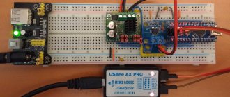
During the measurements, it became necessary to visually monitor the alternating signal on an oscilloscope. However, connecting an oscilloscope directly into the signal circuit before the rectifier led to signal distortion. For resistance matching, buffer stages were added in front of the active rectifier.
The installed buffer stages made it possible to separate the signal into two channels without changing the signal characteristics. The cascades were made on a similar high-speed operational amplifier (LM833), from one output of which the signal was fed to an active rectifier, and from the other to an oscilloscope
Measuring inductances
Measuring inductances is somewhat more complicated. This is due to the fact that any coil (winding of a transformer, etc.) has, in addition to inductance, also resistive resistance. Therefore, in many cases, the impedance of the inductor is first measured:
It can be determined by the ammeter and voltmeter method by measuring voltage and current with measuring instruments of an alternating voltage circuit (Fig. 7, a) z = U/I. When a constant voltage is applied to the circuit (Fig. 7, b), as discussed above, the resistive resistance of the coil R can be determined.
Rice. 7. Inductance measurement circuits
Then
In turn, inductive reactance
With a known value of frequency / supply voltage, it is easy to find the value of the desired inductance value
For small inductance values (for example, loop coils of radio-electronic devices), you can use a resonant circuit, similar to the circuit for determining capacitance by the resonant method.
To measure inductance, you can also use alternating current bridges and special measuring instruments—kumeters—that allow you to determine not only the inductance value, but also such a characteristic as the quality factor of the coil, which characterizes the quality of the coil’s operation in electronic circuits.