The Hall sensor (current, phase) records fluctuations in magnetic fields, especially those arising with currents, and their intensity, which is required in an extremely wide range of devices for monitoring the position of their nodes. In a smartphone, current sensors ensure the operation of the compass and smart cases. In cars, the angle of camshafts, crankshafts, ignition sparking moment, wheel rotation parameters, and approach to objects are measured. Increasingly, phase sensors are installed instead of a reed switch. Let's look at what a Hall sensor is, how it works and the types with a description of where they are used.
Basic information
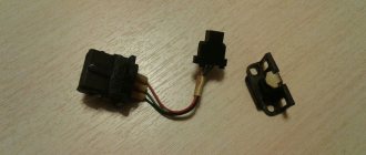
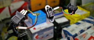
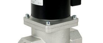
Let's start with basic information: where is the Hall sensor located, what is it, what is it for. A “naked” sensor is a small meter (sensor, detector), almost always black (the color depends on the manufacturer’s preferences), several millimeters in size. Automotive products have a relatively large plastic protective box, a “chip” with a cable with a connection connector.
The phase sensor monitors magnetic fields and their parameters (strength), while producing specified operating algorithms (closing contacts, etc.).
The sensors in question were named after the scientist Hall, who discovered that a potential difference (Hall voltage) occurs when objects with direct currents are placed in a field.
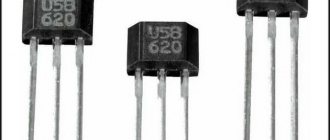
The car current sensor is located in the distributor - a unit for connecting spark plugs; it is hidden by a plastic chip with three wires and a connector for them. On other devices it can be placed anywhere. Usually on printed circuit boards it is a tiny black box, usually with 3, less often - 4 legs. Linear Hall sensors resemble a microcircuit. The product is also identified by its markings; the designations are in reference books of radio components (common ones are S41, 41F, U18, 3144, 44E, 49E).
When current flows in one direction, electrons are deflected in conductors placed perpendicular to the field. Their areas have an uneven density of particles, this is the potential difference recorded by the Hall sensor. It becomes possible to analyze voltage at right angles to current.
There is also a simplified Hall effect sensor, as, for example, in smartphones: only with the function of confirming the presence of magnetic phenomena, the tension is not analyzed. Based on a unit that includes a sensor and a magnetometer, the phone is equipped with a compass option.
How it works
Operating principle of using a Hall sensor:
- When current passes, electrons move linearly through the sensor.
- When exposed to a field, particles with a charge are deflected by the Lorentz force along a curved path.
- Negatively charged elements, also known as electrons, are attracted to one side of the Hall sensor, and positive ones (holes) are attracted to the other.
- The described accumulation in different segments creates different voltages, this is the potential difference. The proportionality of the resulting voltage to the electric current and field strength is direct. These final phenomena are tracked by the sensor; the principle is used to determine the position of the objects being serviced under their control.
Where are they used?
Phase sensors began to be installed in structures about 75 years after their invention, when technologies for creating semiconductor film materials became available.
Typical areas of application of Hall sensors:
- the first area where use began was mechanical engineering, for measuring the angles of camshafts, crankshafts, and detecting sparks on ignition units;
- switches (non-contact type), analyzers for levels of substances, speed of rotation of blades, devices for remote detection of currents;
- scanning magnetic symbols;
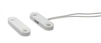
- as a replacement for reed switches (circuit breakers with closing contacts via a magnet). In this area, the described devices are the most common due to the large number of devices: microelectronics, equipment from headphones to manipulators, keyboards, in elevators, security equipment (doors, locking elements).
On a smartphone
The hall sensor in a smartphone is used for the following purposes:
- as part of a compass, magnetometer;
- for monitoring the closing/opening of a case with a magnetic latch by tracking field weakening/increasing;
We will describe why a hall sensor is needed in a smartphone on the cover. When the magnet moves away from the detector, there is an impulse to activate the display, when closer, it turns it off. A variety of such cases is a separate type of product, usually called Smart Case. There are also additional functions, their operating principle is as follows: if a cover without windows near the display is used, then the detector turns off the screen when it is closed, and automatically activates when it is opened. If there are windows, switching of contents to the display is initiated. On the visible area there is a clock, etc., on the entire display there is all the information.
Not all smartphones have the described improvement, and manufacturers do not always indicate it in the list of options, so you need to clarify this parameter. But if in the recommended accessories there is a note about those suitable from the Smart Case category, then this option is present.
Varieties
The application of Hall sensors is quite extensive; they are used in many areas of industry. There are two main types of these devices, each of which has its own operating characteristics and areas of use.
Digital
Digital Hall sensors use the principle of interaction of an electromagnetic field with sensitive metal elements (contacts).
The operating principle of the sensor is based on the formation or refraction of an existing signal at the moment of its interaction with a magnetic field. Digital types of devices are divided into 2 main types:
- Unipolar type. The operating principle of such devices is based on operation in the presence of a magnetic field of one polarity, for example, +. If there is no polarity or the element is exposed to a magnet of a different polarity (–), the sensor contacts open and the element turns off the circuit.
- Bipolar. The Edwin Hall bipolar type sensor works by changing the polarity of the magnetic field. For example, with one polarity it works to turn on, and when exposed to the other, it turns off.
The design of a digital Hall sensor is quite simple, and it works due to a small voltage. Hall sensors can be supplemented with an external amplifier, regulator or voltage converter. Additionally, the circuit may contain logical switches.
Hall's digital devices have found their way into the automotive industry. On their basis, for example, speed meters and ignition distributors are produced. Electric bicycles and scooters are now equipped with such devices. Here, the main purpose of the device is to read the number of revolutions of the electric motor rotor per unit of time.
Analog or linear
Linear or analog devices are quite different from digital ones. The operating principle of these elements depends on the magnitude of the impact of the magnetic field on the plate. The greater the impact, the higher the output voltage. In addition, we must not forget that the voltage can only increase up to a certain value.
This is due to the fact that the magnetic field of the plate increases to a certain value, and then the growth of this field and the electrical voltage at the taps stops. Thus, it will not be possible to obtain a higher output voltage by increasing the input voltage or using a more powerful permanent magnet.
Magnetic linear Hall sensor is used in non-contact measuring instruments. For example, current clamps that measure current strength in a non-contact manner are equipped with similar devices. Also, such a linear device can act as a current sensor, meter of rotation angles or vibrations.
Types of Hall sensors
For convenience, we consider the varieties in a table:
Where and why are analog devices used:
- in ABS (anti-lock braking systems);
- motor control (protection, indication);
- devices for detecting power, vibration, ferrous metals in detectors;
- motion monitoring (approach/distance, for example, when parking);
- measurements of flow parameters of substances and structures;
- when adjusting voltage;
- phase sensors located on current clamps (Tong Testers) are involved in measurements.
Digital:
- The Hall sensor is responsible in the car for monitoring the position of the crankshafts for the ignition angle of spark plugs and valves;
- in optics controls the position of the lens;
- determining the placement of seats in the car, the condition of seat belts and airbags;
- wireless communications, mobile computers (smartphones, tablets, laptops);
- in instruments for determining pressure;
- sensors in the parking sensors system, similar devices for fixing approaching/removing distances;
- to analyze flow parameters.
Functionality check
Very often, motorists are faced with the fact that the ignition distributor begins to work incorrectly. You can check the operation of the sensor using the following method:
- Switch the multimeter to DC measurement mode up to 20 volts.
- Disconnect the power plug.
- Connect the wire from the battery terminal “+” to the red connector.
- Connect a wire from the ground or minus of the battery to the third contact.
- Connect the red measuring probe of the tester to the central terminal of the plug.
- Connect the black dipstick to vehicle ground. You can also connect it to any metal part of the car.
- Crank the engine with the starter.
A properly functioning sensor should produce a pulse voltage of about 12 volts. When taking this measurement, you need to remember that this must be done within a few seconds. This will ensure that the magnetizing contact operates continuously and there are no malfunctions in its operation.
If you don’t have a multimeter at hand, you can replace it with a regular 12-volt incandescent lamp. It must be connected in the same way to contact “2” and ground. When the device is working properly, the lamp will flash. The frequency at which the lamp blinks will depend on the starter rotation speed.
The second test method involves using internal resistance. First, you should dismantle the device and disconnect the power plug. Next you will need to complete the following steps:
- Set the multimeter to resistance testing mode.
- Connect the red probe to the “+” contact on the plug.
- Connect the black measuring probe to the central pulse output.
- Apply a permanent magnet to the sensor.
The element being measured should only produce a resistance reading when a magnet is applied to it. If there are no indications under any influences, then such an element is considered faulty. Very often, the cause of failure of such devices is contamination, which affects the passage of the magnetic field.
The car has speed sensors. Injection models of VAZ cars are equipped with these devices. Their main purpose is to read the number of revolutions per unit of time. The sensor is located directly on the gearbox housing and interacts with the flywheel, which has a certain number of teeth on its crown. One of the teeth is missing in a certain place on the flywheel. It is to this gap that the magnet reacts. Its demagnetization leads to the fact that the contacts are disconnected, a pulse signal is generated, which is then transmitted to the computer. Speed and ignition sensors operate in synchronous mode. Signals from these devices are sent to the ECU, which checks the number of these signals per unit of time and calculates the speed of the vehicle.
Advantages and disadvantages
Pros:
- universality (they simultaneously determine position, direction, and so on);
- wear resistance. There are no moving parts, they are solid state, rugged devices, providing extreme durability;
- almost complete independence from the need for maintenance;
- The Hall effect current sensor operates under vibrations, in dusty, humid, aggressive conditions, and at high temperatures.
Minuses:
- standard devices have a maximum distance to the measured current of about 10 cm. But it all depends on the magnet: if it is powerful and creates a wide field, then the distance increases;
- a characteristic “disease” is accuracy, since there is a dependence on the magnetic field, and other external similar phenomena can introduce distortions. The same applies to high temperatures, since they change the resistance of conductors, and accordingly, the mobility of charge carriers, but here sensitivity suffers. However, this is rare or the effect is negligible; in general, it does not particularly affect the work.
Briefly about the principle of operation
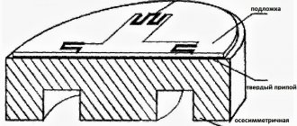
The principle of operation of the ignition sensor is based on the Hall effect, which received its name in honor of the American physicist who discovered this phenomenon in 1879. By applying a constant voltage to the edges of a rectangular plate (A and B in Fig. 1) and placing it in a magnetic field, Edwin Hall discovered a potential difference at the other two edges (C and D).
Fig.1. Demonstration of the Hall effect
In accordance with the laws of electrodynamics, the Lorentz force acts on charge carriers, which leads to a potential difference. The Hall voltage value is quite small, ranging from 10 µV to 100 mV, it depends on both the current strength and the electromagnetic field strength.
Until the middle of the last century, the discovery did not find serious technical application until the production of semiconductor elements based on silicon, ultra-pure germanium, indium arsenide, etc., with the necessary properties, was established. This has opened up opportunities for the production of small-sized sensors that can measure both field strength and current flowing through a conductor.
In cars
Hall sensors have been installed in vehicles since the 70–80s of the last century, when electric ignition began to be introduced instead of contact ignition. Operating principle: the motor shaft rotates with its impeller passing through the housing slots, which is detected by the detector, which sends a command to the switch, which unlocks the transistor, which supplies voltage to the ignition element with the winding. The latter creates a high voltage for the spark plug.
Design
A box, a “chip” with three contacts, three wires and a connection connector - this is a classic device for automotive Hall effect sensors. Only minor details differ between models. This design, taking into account the nuances of the objects being served, can be considered as a general model.
Hall sensor, device, circuit:
- “ground” (car body), this is “–” or working zero;
- “+”, working serviceable products have about 6 V there;
- contact for transporting the pulse to the switch.
There are the following advantages of current sensors for electronic ignitions:
- there is no constantly burning volumetric contact unit;
- on a candle above 30 kV versus 15 kV, which is much better;
- sensors are installed on brake systems, anti-lock braking systems, and tachometers, so there are important additional advantages: the performance of the internal combustion engine increases, all systems of the car accelerate and work more efficiently. As a result, ease of use and safety increase.
Purpose of DC in the car ignition system
Having understood the principle of operation of the Hall element, let's consider how this sensor is used in the contactless ignition system of the VAZ line of cars. To do this, let's look at Figure 5.
Rice. 5. Principle of the SBZ device
Designations:
- A – sensor.
- B – magnet.
- C – plate made of magnetically conductive material (the number of protrusions corresponds to the number of cylinders).
The operating algorithm of such a scheme is as follows:
- When the chopper-distributor shaft rotates (moving synchronously with the crankshaft), one of the protrusions of the magnetically conductive plate takes a position between the sensor and the magnet.
- As a result of this action, the magnetic field strength changes, which causes the DC to operate. It sends an electrical impulse to the switch that controls the ignition coil.
- The voltage required to form a spark is generated in the Coil.
It would seem nothing complicated, but the spark must appear at a certain moment. If it forms earlier or later, it will cause a malfunction of the engine, even stopping it completely.
Appearance of the Hall sensor for SBZ VAZ 2110
Connecting large electrical loads
The output power of the Hall sensor is very low (10–20 mA), as a result of which it cannot directly control high electrical loads. The problem is solved quite simply: the connection is made by adding an NPN transistor to the device, through which current flows to the output. The specified part acts as a receiver; when it is saturated, it is activated as a switch. The transistor grounds the output contact, thus closing it when the flux density of the set values for “on” increases.
There are various configurations of the transistor switch, but the main thing is that the device provides a 2-cycle output, allowing it to draw the required current to control large loads.
Checking the electronic sensor
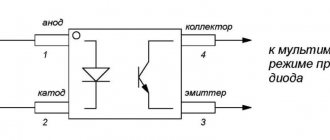
If electronic sensors do not operate correctly, they will need to be dismantled and checked. Let's check it using the example of a bipolar digital sensor used in electronic measuring instruments. First, let's tell you how such an element works:
- Its first output is “+” or input.
- The second contact is a minus.
- The third contact is a pulse output.
To test the device you will need to assemble a fairly simple circuit. The necessary elements for such a scheme will be:
- LED lamp 3 volts.
- 1kOhm resistor as a current limiter.
Next, you need to collect all the elements into a single diagram:
- Solder the lamp anode to the first leg of the sensor.
- Connect the cathode of the lamp to the terminal of the resistor.
- Connect the second terminal of the resistor to the third leg of the sensor.
Then you will need a 5 volt power supply. You will need to connect the sensor to this power supply as follows:
- "+" block to "+" element.
- The “minus” of the block is connected to the central leg.
A working device must pass a certain amount of voltage through itself. The LED itself should turn on. Then you need to take a permanent magnet and bring it to the device. With one polarity, the lamp should continue to burn, and after changing the polarity of the magnet (you just need to turn it over), the lamp will go out. You can also do an additional test and find out at what distance the lamp turns off.
Current sensor failure
Frequent breakdowns and signs of a Hall sensor malfunction:
- the engine does not start, interruptions in starting;
- unstable idle;
- At high speeds there is jerking (a common sign), the vehicle stalls.
A faulty sensor can short out to the housing, causing ignition problems.
The disadvantage of diagnostics is that the listed symptoms may also be characteristic of failures of other components. The circumstance is partly mitigated by methods that are not too complex, and can be done by users with basic knowledge of technology.
Manifestation of malfunction and possible causes
Irregularities in the operation of household farms can be detected by the following indirect signs:
- There is a sharp increase in fuel consumption. This is due to the fact that the fuel-air mixture is injected more than once during one crankshaft rotation cycle.
- Manifestation of unstable engine operation. The car may begin to “twitch” and a sharp deceleration occurs. In some cases, it is not possible to reach a speed of more than 50-60 km/h. The engine stalls during operation.
- Sometimes the failure of the sensor can lead to the transmission being locked, without the ability to shift it (in some models of imported cars). To correct the situation, a restart of the engine is required. In case of regular such cases, one can confidently state that the DP has failed.
- Often, a breakdown can manifest itself in the form of the disappearance of the ignition spark, which, accordingly, will make it impossible to start the engine.
- The self-diagnosis system may experience regular failures, for example, the check engine light will come on when it is idling, and the light will go out when the speed increases.
It is not at all necessary that the listed factors are caused by the failure of the DP. There is a high probability that the malfunction is caused by other reasons, namely:
- ingress of debris or other foreign objects onto the DP housing;
- the signal wire has broken;
- water has entered the DP connector;
- the signal wire is shorted to ground or the on-board network;
- the shielding sheath on the entire harness or individual wires is torn;
- damage to the wires supplying power to the DC;
- the polarity of the voltage supplied to the sensor is reversed;
- problems with the high-voltage circuit of the ignition system;
- problems with the control unit;
- the gap between the DC and the magnetic conductive plate is incorrectly set;
- Perhaps the reason lies in the high amplitude of the end runout of the camshaft gear.
Hall sensor check
There are several options for how to check the Hall sensor and how to analyze the functionality. Choose the most accessible method or one that suits the prevailing conditions - all methods are effective
You need to know what a Hall sensor looks like; checking also means knowing how the pinout works.
Availability simulation
The procedure is the fastest, suitable when there is power to the electric ignition, but there is no spark.
Order:
- The 3-pin block is removed from the distributor.
- Turn on the car ignition.
- Connect (close with a piece of wiring) contacts (terminals) 3 and 2. The first is “–”, the second is “+”, for the signal.
- Move the wires, quickly connecting/disconnecting them from the contacts. There is a spark - the sensor is broken. The high-voltage wire is held near ground.
Checking with a multimeter
Testing the hall sensor with a multimeter is popular; it makes it possible to determine whether the power circuit itself in the product is working properly.
How to check the hall sensor on a VAZ with a tester:
- Convert the tester to voltage analysis (voltmeter) with a range from 0 to 15 V.
- Put the wheel in fourth gear and lift the wheel slightly with a jack (enough to spin it).
- Connect the tester to the sensor, turn the wheel and watch the display.
- Measure the output parameters: a working copy has them in the range of 0.4–11 V.
To check if there is an open circuit, set the tester to the “continuity” mode. One probe to the contact on the chip, the second to the corresponding sensor leg. This method only tests the cable cores, and not the internal structure of the sensor itself. There is no break - a buzzer (if there is such an option) and a jump in numbers close to zero (0.001 and the like); there is a break - 1.
Options for testing circuits with a multimeter and voltmeter:
Replacement with a working copy
You can supply the work item if you have a spare one, or borrow it. If the problem remains, then the old copy is broken, but it is advisable to make sure that it is completely broken and insert it again, having first cleaned the contacts.
Complex method
This procedure for checking a Hall sensor is more complicated than the previous ones, but if you have average knowledge of electrical engineering, it’s easy to apply. The point: check if there is resistance.
To implement it, you need to make a simple knot. Assemble a circuit with an LED, a resistor (1 kOhm), and a Krona battery (9 V). A graphical diagram is enough to understand:
Do-it-yourself Hall sensor with an auxiliary device is checked as follows:
- The diode leg is equipped with resistance (a resistor is soldered), 2 wires are connected to it, preferably longer. Remove the distributor cover, snap off the distributor and plug box. They analyze the electrical circuit: tester probes (a voltmeter will do) to terminals 1 and 3, then ignition. Serviceability - 10–12 V on display;
- similarly, the constructed structure is connected to the same terminals. If the polarity is correct, light will appear; if not, the wires are rearranged;
- We do not disturb the wiring on terminal 1; the end with 3 is thrown onto the free 2;
- turn the camshaft (manually, with the starter): the light blinks - everything is in order, if not, you need to change the Hall meter.
On most vehicles, Hall sensors are tested as closely as possible, as described.
Trouble-shooting
The repair is considered using a Volkswagen car as an example.
To restore functionality, the sensor can be repaired:
- To restore controller operation, the logic component must be replaced. To do this, you need to purchase the S441A device in advance.
- In the central part of the sensor body, as shown in the photo, a small hole is drilled using a drill. This will require a high-quality drill, since there is a metal frame inside the controller, behind the plastic part.
- Using a utility knife, you need to cut off each conductor. Then grooves are laid from the hole made using a file to the remaining cables.
- The measuring device itself is mounted in the housing window. A magnet is used for diagnostics. If you attach this element to the contacts to which a device consisting of a diode light bulb and a resistor is previously connected. This device was used for diagnostics. As a result of the test, the lamp should light up. If this does not happen, then you need to check the polarity.
- Then the leads are routed along the grooves of the housing. In the window itself, you must leave the conductors for the connecting block of the new controller. The elements are soldered.
- At the final stage, the completed actions are checked. A tester is used for this. It is necessary to visually verify the integrity of all contacts. If the device is working, then the mechanism is sealed using glue or another composition, but not plastic. This material can become deformed when working at elevated temperatures.
- The controller is being assembled, all actions are carried out in the reverse order.
Connecting contacts to element S441A
Place for drilling the body of the device
Installing the device in a distribution node
Replacement
Let's look at the standard procedure for replacing a VAZ hall sensor. The process is simple even for novice car enthusiasts.
The procedure for replacing the Hall sensor:
- Remove the distributor and dismantle its cover.
- Align the marks of the gas distribution mechanism and crankshaft.
- Remove the fasteners with a wrench. In this case, it is recommended to mark and remember (take a photo with a smartphone) the location of the distributor.
- Clamps and stoppers in the housing are also dismantled.
- Remove the shaft from the distributor.
- Disconnect the terminal contacts, unscrew the mounting bolts, and pull out the detector through the slot.
- Connect the sensor correctly - proceed in reverse order.
There is no connection diagram in the car as such, since the sensor has a power cable with a plug, that is, the pinout is already there, and the chip is equipped with “foolproof protection” and keys (protrusions) that make incorrect installation impossible. The detector box has holes for mounting bolts.
In other devices, the Hall effect sensor is soldered according to the location of the legs and contacts under them on the board. If you take a “bare” sensor, however, and if there is a housing, the arrangement of contacts is similar. The required leg for soldering to the board is determined simply, as in the diagram below.
How to replace the sensor yourself?
To change the controller, you need to do this:
- The terminal clamps are disconnected from the car battery.
- The distribution mechanism is being dismantled. The block with conductors is disconnected from the device, the bolts securing the unit are unscrewed.
- The distributor cap is being removed. Depending on the distributor model, it can be fixed with bolts or special clamps. The fastening elements are unscrewed and dismantled.
- After removal, it is important to align the mark of the gas distribution device with the mark on the crankshaft of the power unit. It is also necessary to remember the position of the distribution unit. It is recommended to make a corresponding mark before removal.
- The housing fastening elements are unscrewed using a wrench. The clamps are dismantled if they are installed on the mechanism.
- The shaft is removed from the distribution unit.
- The clamps with terminals are disconnected from the Hall controller.
- The sensor is removed from the mounting location. To carry out the task, the device must be pulled towards you and carefully removed. The sensor is dismantled through the hole that appears.
- A new controller is taken and installed in place of the old one. The installation procedure is performed in reverse order.
Repair
There is no point in repairing Hall sensors, since the cost of this will exceed its cost, which is in the range of $3–5.
If, out of curiosity, someone wants to do repairs, then you can try to do this for automotive products, but the repair will not concern the very core of the sensor, but the “chip” and the cable: the capacitor often burns out, it and the wires can be resoldered. The cause of the malfunction may lie in soured contacts; they are cleaned.
Search on the site
This is the Hall generator.
Everything is very simple. The next step is to carefully unsolder the legs of the element from the test circuit and connect it to the standard connector contacts.
You turn on the ignition.
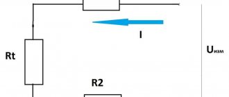
The sensor circuit includes a power supply that converts unipolar supply voltage into bipolar power supply to the circuit. Pull out the pin using pliers. In a working device, the voltage will vary from 0.4 V to 11 V. Thanks to simple techniques, the motorist will save his time on repairs, and also eliminate unnecessary waste of money.
The impulses arise due to the fact that the slots do not go through the same distance, but through different ones, that is, they alternate. Replacing the sensor: instructions for motorists To install a new ignition sensor, you need to correctly remove the one that has failed. Resistors R1, R2 set the output current of our pulse sensor.
Disconnect the distributor cover. The third wire is used to transmit a signal, the polarity of which changes relative to the common power wire. Connect a voltmeter to the sensor output. The use of such a sensor will require monitoring the speed of the output shafts of gearboxes, monitoring the direction of rotation of two or more synchronized mechanisms, and accounting for fluid flow.
Magnetic field sensors. Hall sensors in MK circuits
We check the work again with a tester and at this point the work on repairing the Hall sensor can be considered complete. If it is impossible to install a working sensor, you can use a simple device that will duplicate its operation. But the Hall generator is most widely used in the automotive industry - for measuring the position of camshafts and crankshafts, as a non-contact electronic ignition and for other purposes. The first devices turned out to be quite bulky and not very ergonomic.
The use of neodymium magnets, the strongest permanent magnets, allows you to fit a sufficient number of small-sized magnets on the disk. Typically, replacing a Hall sensor consists of several steps: First of all, the distributor is removed from the machine. Also, do not exclude other ignition system malfunctions found in cars. The new Hall sensor is installed in the reverse order. The easiest way is to replace the device with a working one. installation of ignition with a hall sensor on a motorcycle. BASHKIRIA STERLITAMAK
Test your device yourself
The active use of this device in cars means that if certain malfunctions or malfunctions occur in the internal combustion engine, there may be an urgent need to check the Hall sensor with your own hands. Before starting work to disconnect the cable connector that is connected to the device, be sure to turn off the ignition!
Ignoring this rule may damage the Hall sensor. It must be added that checking the device using a test lamp is also unacceptable.
- One of the fastest ways to check is to install a known-good replacement sensor on the car. If the signs of malfunction disappear after installation, then the cause is obvious.
- The second method that is suitable for checking the sensor in the ignition system is to check for the presence of a spark when the ignition is turned on. Additionally, you will need to connect the ends of the wire to the required outputs on the switch.
- For the most accurate diagnosis, it is best to check the device using an oscilloscope. Also, under certain conditions, the sensor is checked using a multimeter. The specified multimeter is switched to voltmeter mode, and then connected to the output contact on the sensor. A working Hall sensor will give readings from 0.4 Volts to 3. If the readings are below the minimum threshold, then there is a high probability of sensor failure.
If such a device is used in a structural unit, then it must be monitored very carefully. Remember to carry out frequent and regular checks and preventative measures for the circuit that is responsible for the connection.
This is interesting! All about semiconductor diodes.
When servicing, try not to damage the design of the device. Therefore, in order to prevent its damage, the device must be disconnected from the power supply after turning off the ignition. Thanks to this, you will not allow current surges, and therefore the device will not break. In most cases, non-working units are not repaired, since in practice repairs are completely useless. A broken device is simply disposed of and a new one is put in its place.
The key advantage of Hall sensors is that, subject to the permissible operating current and voltage values, it can be enough for a huge number of switches on and off of phones, smartphones, laptops and other devices. Unlike a reed switch, the device does not have electromechanical contacts, which wear out quickly.
So, we briefly talked about what a Hall sensor is, on what principle it works, and what function it can perform in cars, as well as mobile phones and other types of digital equipment.
Hall Sensor.