Solenoids are used in many applications to provide linear or rotational actuation of mechanical systems. Although controlling a solenoid can be as simple as turning a load (such as a switch) on and off, often higher performance can be achieved using an application specific integrated circuit (ASIC) ) to control it.
In this article we will look at how the electric drive control system affects the electromechanical characteristics of the solenoids. Two different circuits will be compared: a simple switch and a current control driver. Energy saving technologies that limit power dissipation in the solenoid will also be discussed.
Solenoid operating principle
The most primitive solenoid design is a coil that creates a magnetic field. The devices we call solenoids consist of a coil and a moving core of iron or other material. When current is applied to the coil, the core is retracted and causes the mechanical object connected to the core to move. A simple solenoid is shown below:
To drive the core, voltage is applied to the coil. Since the inductive reactance of the coil is quite large, to speed up the response processes, an increased voltage is applied to the coil. The pulling force of the core is proportional to the current.
Much less current is required to keep the mechanical device in the core. If the current in the coil is not reduced after the mechanical device has reached its end point, this will cause the solenoid to heat up significantly more.
To solve this problem, you can use a constant current driver. The current can be controlled over time to ensure minimal heat loss while maintaining the maximum required holding torque.
How to properly wind the coils on the solenoid?
I need to wind a small electromagnet "solenoid?". About 3cm high and 2~5cm wide at 5V/0.5A. This magnet will be placed in the table bell to pull the beater and ring the bell. I found pre-made solenoids that push but don't pull.
So I'm trying to make my own magnet and have wound several different types of screws, nails and bolts with different types of wire. And now I noticed a problem with accuracy. I can wind a massive coil and it will work, but how do I wind a small but powerful coil?
I can't find a layman's explanation on what core diameter cable to use and how many windings. In general, the more windings, the stronger the field, which is common to all the articles I read.
I found an article where someone says the windings should be wound in the same direction (clockwise layer, clockwise layer, etc.) to create a truly stronger solenoid, but all the articles say just wind them back and forth (magnet?)
Can anyone at all suggest what type of core and core diameter would be best and if winding the coils in the same direction would really help. Also is there any difference in how the ends are directed or are both sides emitting the same field?
At the moment I have a PCB with 3 1000 uF caps in parallel with a coil that is driven by a transistor. I'll use aTiny which triggers the transistor for maybe 0.2 seconds and I need a push of magnetic force to pull the latch and instantly release.
- created using CircuitLab
-EDIT
This is a project that someone worked on using USB power and winding their own coil. Does it use a Darlington transistor? Does this affect the coil in any way? I only have a normal transistor. The gap should be about 1.5~2cm to allow the beater to hit the bell. I got the same call. He thinks he used 2m of cable to wind the coil... I used 3.5m and wound it much neater than his...
- BDX53B Darlington transistor
- 1 x 2200 uF 10 V
YouTube
-EDIT2
I ended up using a 5v solenoid. I removed the 2 capacitors and used the push end of the solenoid to pop the plug out. AND DING! Works great. I have no idea how this guy got this electromagnet to break the cracker?!
Test setup
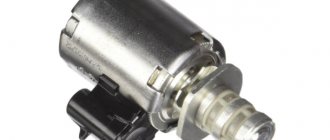
To compare the electromechanical performance of different solenoid drive circuits, a simple test setup was created using a servo amplifier connected to a solenoid with a bend to measure the solenoid's movement. The motion, along with the voltage and current, was recorded using an oscilloscope. An MPS MPQ6610 IC was used to control the solenoid.
Operating principle
The fundamental principle of working with a solenoid is the following: control current through the winding causes the plunger (piston) to move in the direction of the magnetic field, that is, into the area covered by the winding. Changing the polarity of the applied voltage does not change the direction of movement, because a typical plunger is just a piece of metal (not a magnet), and therefore it is always attracted (not repelled) by a magnetic field.
If gravity or something in your mechanical load is not returning the piston to its original position, you need a spring return solenoid.
Simple drivers for solenoids
The easiest way to control a solenoid is to turn the current on and off. This is often done using a low side MOSFET switch and a current protection diode (picture below). In this circuit, the current is limited only by the supply voltage and the constant resistance of the solenoid.
The electromechanical performance of a simple solenoid actuator is limited. Since full voltage and current are applied 100% of the time, the pull-in current is limited by the constant power dissipation of the solenoid. The large inductance of the coil limits the rate of current rise when the solenoid is turned on.
The test measured the movement, voltage and current of a solenoid activated using a simple switch (picture below). In this case, the solenoid (15 ohm rated at 12 V) took 30 ms to turn on to drive the mechanical drive and dissipate 10 W of power.
If you are wondering about the "valley" in the current waveform, this decrease in current is due to the back EMF created by the moving solenoid core. The back EMF increases as the core accelerates until the solenoid retracts and stops.
Magnetic field of electric current
The magnetic field is created not only by natural or artificial permanent magnets, but also by a conductor if an electric current passes through it. As follows, there is a connection between magnetic and electronic phenomena.
It is not difficult to verify that a magnetic field appears around a conductor through which current flows. Place a straight conductor above the movable magnetic needle, parallel to it, and pass an electric current through it. The arrow will take a position perpendicular to the conductor.
What forces could force the magnetic needle to turn around? Of course, the strength of the magnetic field that appears around the conductor. Turn off the current and the magnetic needle will return to its normal position. This means that when the current was turned off, the magnetic field of the conductor also disappeared.
Thus, an electric current passing through a conductor creates a magnetic field. To find out in which direction the magnetic needle will deviate, use the right-hand rule. If you place your right hand over the conductor, palm down, so that the direction of the current coincides with the direction of the fingers, then the bent thumb will show the direction of difference of the north pole of the magnetic needle placed under the conductor. Using this rule and knowing the polarity of the arrow, you can also find the direction of the current in the conductor.
The magnetic field of a conductor has the shape of concentric circles. If you place your right hand over the conductor, palm down, so that the current seems to come out of the fingers, then the bent thumb will point to the north pole of the magnetic needle. This field is called a radial magnetic field.
The direction of the radial field lines depends on the direction of the electron current in the conductor and is determined by the so-called “gimlet” rule. If the gimlet is figuratively screwed in the direction of the current, then the direction of rotation of his hand will coincide with the direction of the magnetic field lines. By applying this rule, it is possible to find out the direction of the current in a conductor, if the direction of the field lines created by this current is clear.
Returning to the experiment with the magnetic needle, we can be convinced that it is always placed with its northern end in the direction of the magnetic field lines.
So, a magnetic field appears around the conductor through which electric current passes. It has the shape of concentric circles and is called a radial magnetic field.
High Performance Solenoid Driver
In most applications, full current is only needed to retract the solenoid. Once the movement is completed, the current level in the solenoid can be reduced, resulting in energy savings and significantly less heat generated in the coil. This also allows the use of a higher supply voltage, which boosts the pull-in current to make the solenoid core retract faster and provide greater pull-in force.
The powerful MPS MPQ6610 half bridge, together with several external components, can accomplish this task (picture below). The MPQ6610 is rated at 60V and 3A and is available in small TSOT and SOIC packages.
The resulting excitation signals are shown in the figure below. The yellow line is the OUT signal that controls the solenoid, and the green line is the solenoid current. Initially the full supply voltage is 24 V (in this case the solenoid is driven). After a delay, the current is reduced by pulse width modulation of the output. Retraction time is reduced to 16 ms and hold power dissipation is significantly lower (about 600 mW instead of 10 W).
This scheme works as follows:
Initially the input signal is low. This discharges C1-D1 and keeps the ISET pin low at Q1.
The input signal ramps up, allowing the MPQ6610 to “boost” the output signal to a high level by applying the full supply voltage to the solenoid. C1 starts charging through R1. The current comes from the ISET pin, which is proportional to the current flowing in the solenoid. As C1 charges, the voltage at the ISET pin may increase.
Assuming there is sufficient current in the solenoid, the ISET bus voltage continues to rise until it reaches its current regulation threshold (1.5 V). At this point, the MPQ6610 begins to regulate the solenoid current. The adjustable holding current is set by the value of R2.
The delay time (when the solenoid is driven to 100% duty cycle) is set by the values of R1 and C1. For a standard 3.3V logic level, the time is approximately 0.33×RC. For the example above, with R1 = 100 kΩ and C1 = 2.2 µF, 0.33 × RC = 75 ms.
see also
Wiktionary has an entry for "solenoid"
- Magnet
- Electromagnet
- Inductance
- Inductor
- Ruhmkorff coil
| : Incorrect or missing image | This article lacks links to sources of information. Information must be verifiable, otherwise it may be questioned and deleted. You may edit this article to include links to authoritative sources. This mark is set May 4, 2013 . |
K:Wikipedia:Articles without sources (type: not specified)