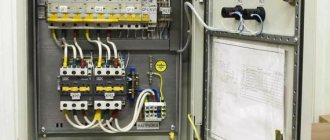
To optimize the control of lighting fixtures throughout the house, a system device is used. It helps you turn off the lights with just one button.
The system apparatus consists of individual elements:
1) Contactor is an electromagnetic switch that is designed to remotely close and open electrical circuits.
2) Control module, which consists of:
- a regular 2-key switch.
- electric key scanner (contactless) and cards;
- Wi-Fi or GSM remote control unit.
3). An RCD is an automatic device equipped with a protective shutdown mechanism and ensures the safety of the entire system.
Residual current device Source shikalad.ru
We connect the lighting in the house with a master switch: diagram
To implement such projects, you will need modular contactors for the master switch, for example, ABB ESB 20-20.
The letters and numbers in the name have a specific meaning. The marking symbols mean:
- АBB – name of the organization, manufacturer of the device.
- ESB – circuit breaker series, has a household purpose.
- 20 – current value calculated for the contact element, in A.
- 20-20 – independently closed block contacts with a rated current of 20 A.
Before the pulse arrives, the contact elements are constantly in the open state.
Automatic control circuits
But be that as it may, manual control schemes require human participation. And this is not always possible or comfortable.
It is much more convenient if the lighting turns on independently according to certain factors. For this, remote lighting control and a circuit that requires the presence of special sensors are used.
Circuit with light sensors
For more rational use of electricity, so-called light sensors are used. They allow you to turn on the lights only when the level of natural light decreases to the specified parameters.
At the same time, they do not require human intervention at all, and their maintenance is reduced to periodically wiping the sensor photocell from dust.
The principle of operation of the light sensor is reduced to fixing the level of illumination with a special photocell. When the specified parameters are reached, it is triggered and supplies voltage to the lighting network through a power contact. Adjustment of the required level of illumination is realized through a special regulator on the outer surface of the housing.
Connecting a light sensor does not require special knowledge:
- First of all, we connect phase and zero to the corresponding sensor terminals . They may be designated as "L" or "L1" and "N". This connection ensures the functionality of the device.
Light sensor connection diagrams
- From the third, not yet used output, we connect the lamps . The zero for lamps is taken, in addition to the sensor, directly from the junction box.
Note! According to clause 6.5.7 of the PUE, all systems with automatic lighting control systems must be able to be switched on manually. This is necessary for repairs, network operation, and also in case of sensor failure. This rule applies to all automatic control circuits.
The external lighting control circuit, for which such sensors are most often used, often involves connecting not lamps from the sensor, but a lighting starter.
In this case, when the illumination decreases, the sensor is triggered, then the starter is activated and voltage is supplied to the lighting network, which is controlled either by other sensors or switches. This ensures that the lighting is turned on only when there is insufficient natural light.
Circuit with timer
In some cases, lighting must be turned on when a certain time has passed. In this case, the automatic lighting control circuit is equipped with a timer.
So:
- There are two types of timers: analog, with a clock mechanism, and electronic, the principle of operation of which is similar to the principle of operation of an electronic watch. In addition, timers are divided into real-time devices and countdown devices.
- Real-time devices keep track of time like a regular clock and, when a given time arrives, perform specified actions - turning on or off electrical equipment.
- Countdown devices often have a strictly regulated time period during which it can be triggered - an hour, a day, a week. In this case, you can set actions for not a limited time, but for a given time period. And the timer will keep track of the time until it is triggered.
- Timers themselves are practically never produced. They are often integrated with other devices. This could be circuit breakers, sockets, switches, starters or other equipment.
Sockets with timers
- Modern timers have the ability to program not one, but several actions independent of each other. In addition, modern electronic timers can control several devices at once. But such devices are most often used in smart home lighting circuits and other high-tech circuits like in the video, which can be difficult to create without the help of professionals.
Circuit with motion sensors
The highest degree of energy savings is achieved by a control circuit with motion sensors. The use of these devices allows you to turn on the lighting only while a person is in the room or area of responsibility.
In this case, no participation is required from the person himself. Even the most advanced microcontroller control circuits use this type of sensor to control lighting.
- The principle of operation of the motion sensor is based on recording the infrared radiation emitted by a person. At the same time, in order to record not only the presence of radiation, but also human movement, there is a special optical system. As a person moves, radiation is detected in this system by different elements.
- The number of elements whose activation will trigger the sensor is adjustable. Therefore, with the slightest movement, fixation with two elements is sufficient to trigger the sensor, but for a more coarse setting, fixation with three or four elements may be required.
| When choosing a motion sensor, you should pay attention to a number of parameters. First of all, these are the electrical ratings. First of all, we are interested in the supply voltage, which should be 220V, as well as the rated current of the primary circuit. It can be 6, 10 or 16A. The higher this value, the more lamps we can power from the sensor. |
| Most modern motion sensors have the ability to adjust the light level for triggering, the operating time of the sensor after triggering, and the choice of trigger sensitivity. |
| An important parameter is the angle of operation of the sensor. Most modern models are capable of providing an operating angle of up to 180⁰. And for ceiling-mounted sensors, 360⁰ zone coverage is normal. |
| When setting up motion sensors, as well as their operation, you should remember that bad weather conditions significantly reduce their sensitivity. In addition, placing foreign objects or glass in front of the sensor may completely limit its operation. The same rule applies to climate control equipment installed next to the sensor. |
| Motion sensor design | Another important parameter is the level of protection of the motion sensor from moisture and dust. If for indoor installation you can choose devices without protection, then for outdoor installation it is better to choose products with IP 44 and higher. |
So:
- Connecting a motion sensor is quite similar to connecting a light sensor. In the same way, for the device to work, it needs the presence of a phase and a zero. To power the lamps connected to it, a third wire is used. For the lighting network it is phase.
- In addition, a rather interesting solution is the possibility of connecting them in parallel. For example, we have a corridor with several entrances. Opposite each of them we place a motion sensor, and when at least one of them is triggered, the lighting of the entire corridor turns on. This is the so-called “or” logic.
- Due to their widespread use, modern motion sensors have broader capabilities than just recording movement. In most cases, they contain a built-in timer, and sometimes a light sensor.
- This allows you to significantly expand the range of their use and increase multitasking. For example, you can set the trigger condition for a decrease in the illumination level to a certain value and the appearance of movement. In this case, the sensor must remain in the activated state for so many minutes after the movement has stopped in its coverage area.
- Of course, this is more convenient, but it often increases the final cost of the entire lighting scheme. Therefore, to reduce the cost of the project, our instructions advise integrating several different automatic and manual schemes with each other.
Video description
Master switch. Contactor. Connection diagram.
Contactor connection diagram
It is assembled in the following sequence:
- The single-key light switch receives voltage.
- The current passing through the switch comes to connector A2 on ABB ESB 20-20.
- Its other contact (A1) is permanently connected to “zero”.
The phase conductor is connected to the 1st connector of the contactor, and the wire connecting the lighting devices is connected to the 2nd.
Single-line diagram of a distribution board master switch Source zen.yandex.com
The system operates on the following principle - when you press the light switch button, voltage comes to contact A1, in fact to the contactor coil. Then, according to the law of electromagnetic induction, it becomes closed. In the absence of voltage, contact A1 is open.
After it closes, electric current flows to the equipment. If you press the button of the single-key light switch again, the line is de-energized. Inside the circuit breaker, the connection is broken and the consumer is disconnected from the voltage.
Another group of lighting devices with a rated current of up to 20A is connected to connectors 3 and 4. In total, the control device can withstand a load of no more than 9-10 kW with an allowable current of 40A.
If you assemble a circuit without a contactor, passing the phase of the power cable that connects all groups of lamps through a single-key switch, serious problems will arise:
- A maximum current limitation is created.
This is the value that the switching element that turns off the light can withstand. The value for a single-key switch is rarely more than 10A.
- The switch will quickly fail.
This is due to the fact that it does not have a contact protection system. Therefore, the terminal pads burn out or the housing melts. Sometimes fires happen for this reason.
Switches with remote control, sequentially turning on and off lamps
Let's consider another type of remote-controlled switches, which are equipped only with local control circuits, but have two poles, the contacts of which close and open in series. To briefly designate such switches we use the abbreviation VDUP .
VDUP KM is an electromagnetic pulse switching device that has in its main circuit contacts that make and break the electrical circuits of two lamps or two groups of lamps. The main contacts of a remote controlled circuit breaker are not self-resetting and change their switching position with each current pulse in the control circuit, for example as follows:
- when the first control signal lasting 0.2 s or more appears, the first contact closes, turning on the lamp EL1;
- second signal – the second contact closes, turning on the EL2 lamp;
- third signal - the first contact opens, turning off the lamp EL1;
- fourth signal - the second contact opens, turning off the EL2 lamp.
VDUP KM (based on the diagram from [1] by Yu.V. Kharechko)
Control signals in the local control circuit are created by briefly closing the contacts of any of the push-button switches SB1–SB4 connected in parallel. The contact of the push-button switch returns to its original open position after the mechanical force applied to its control disappears. Any number of push-button switches without signal lights can be connected to the VDUP control circuit. If push-button switches have signal lamps, their number is limited so that the total current of the signal lamps does not exceed 10–20 mA, or special compensators are used.
Using VDUP, you can carry out local control of lamps - sequentially turn on and off two lamps or two groups of lamps from several points where push-button switches are installed, for example, in a corridor or in rooms with several entrances.
In emergency mode, the VDU control circuits can remain under full control voltage for a long time. The main circuits of the VDU should be protected from overcurrents by automatic switches or fuses. The characteristics of overcurrent protection devices must correspond to the electrical load of the main circuit and the characteristics of the VDU, usually: rated main circuit voltage 230 V, rated current 16 A.
Conclusion. Remote-controlled switches have been in production for several decades and are widely used in electrical installations of buildings to control lamps from several points.
Master switch: turn off the light with one button
Some residents associate turning off the lighting throughout the apartment using one button with the Smart Home system, since it is not clear how it works. If we control all the devices, when all the lamps are connected to one controller, then the simplest action is to turn off all the lights at the same time before leaving the house.
This function is implemented very simply; you do not need a “Smart Home” for this. For this purpose, a contactor is installed in the electrical panel, equipped with the ability to turn off the lights in all rooms at once based on an external signal. Some people put an additional device on switched sockets.
The contactor, which simultaneously performs the function of a starter, is a modular element mounted on a DIN rail. The mechanism, based on a control signal, turns off and turns on a powerful load, for example, an ABB ESB 24-40 contactor.
The procedure for connecting machines - what you should always remember
It would seem, what could go wrong when connecting a single-pole circuit breaker?
The technician’s task is to strip the wire of insulation, thread it inside the terminal and tighten it! However, we are full of people with arms growing in the wrong places.
Sorry for such open indignation, but sometimes you just can’t say it any other way. And sometimes mistakes happen among professionals (this is less common), since we are all human, we can get sick, get tired, be overwhelmed with problems and other things that will prevent us from doing our work efficiently.
How to change a machine in a panel - working with electricity always requires a responsible attitude to the matter
So, we got carried away with something. Let's get down to business. We will start with the most important thing - the correct connection of the machines in the panel. Such a switch has two contacts through which it is connected to the network.
What kind of lighting do you prefer?
Built-in Chandelier
One of them is movable, and the second is fixed; they are located at the top and bottom of the device. Do you know which one needs power? Imagine, very few people know about this, since there are constantly debates on this topic on “electrical” forums.
We will not engage in introspection and will turn directly to the PUE, 7th edition, paragraph 3.1.6. It says the following. If the device is powered one-way, then the supply conductor must be connected to a fixed contact.
However, it is worth noting that there is a disclaimer in the form of the phrase “as a rule”, this is a little confusing, as if there are cases that allow an exception to this recommendation. But no further explanations are provided.
Excerpt from the PUE - whenever questions arise, you should seek help from the technical documentation
The same rule applies to all protective devices, circuit breakers and RCDs. To understand where the machine is and what contact is located, you need to know how it works from the inside. Let's dive a little deeper into the world of electrical engineering and look at the structure of a simple single-pole circuit breaker.
- You don’t need to be an engineer to notice that the upper contact of such a machine is fixed, and the lower one is movable. It is not necessary to disassemble the device to recognize the types of contacts. You can also use the markings on its body. Look at the next photo.
The markings on switches from other companies may be slightly different, but, in general, everything is very clear there too. As a last resort, you can always find information on the Internet by making a request for a specific model. In general, almost all modern single-pole circuit breakers have exactly the same arrangement of contacts, but you must make sure of this.
Now let's try to understand the issue from a purely technical approach. So, top or bottom?
- The purpose of the circuit breaker is to protect the line connected to it from short circuits and overloads. It works like this - when overcurrents appear in the circuit, a reaction occurs between the thermal and magnetic releases, which are located inside the device body. At the same time, there is no difference in which side the power cable is connected; the device will work in any case.
- This is confirmed by the fact that some manufacturers, for example, Hager or ABB, allow reverse connection of power to the machine. For these purposes, they are specially equipped with clamps for comb tires.
Hotel circuit and master switch
When there are a lot of lamps and other electrical appliances in the house, and all of them are needed, you can do without turning them on and off at the same time. This is done due to the cross-section of the wires and the current strength of the circuit breaker.
To do this, it is necessary to arrange the electrical wiring in such a way that the circuit diagram includes several circuits that have their own separate circuit breakers. It won't be difficult to do this. With this option, specific groups of electrical appliances are connected to each circuit. Due to this, when all devices are turned on simultaneously, regardless of their power, the current strength in circuit breakers and electrical wiring will not go beyond critical values. This type of electrical circuit is called “hotel” in professional circles.
“Hotel” diagram for connecting a master switch Source rusmarta.ru
To sell you will need to additionally buy:
- a little cable (30-40);
- the required number of machines (depending on the number of circuits);
- master switch, which controls automatic switches through relays.
In appearance, it is a simple key located at the entrance door to the apartment. Such a device allows you to easily turn off the lights in an entire room or turn off a specific group of electrical appliances with a single click.
How to Connect an Automatic Switch: Step-by-Step Instructions
- The quality of switching is undeniable; contact with a branch wire is much more reliable than when using a solid wire as a jumper. Accordingly, overheating of the contact pad and numerous associated problems are practically eliminated.
- In most cases, comb buses for six modules or more are designed for a load of 63A (GOST R 50030.5.1-99). In order for the wire to withstand such a load, it must have a cross-section of at least 16mm 2, which significantly complicates working with it.
- The number of wires in the panel is reduced, which is reflected in the accuracy of the wiring and its clarity. Accordingly, if necessary, dealing with it will not be difficult. To see this, just look at Figure 7.
How to equip the system device
The connection diagram for the master switch depends on where it is planned to be used. Different rooms have their own characteristics, so a competent approach is needed.
In the circuit diagram, the circuit breaker is located at the beginning of the electrical circuit. In fact, it is located in the house next to the meter.
Connection diagram for modular contactor Source strojdvor.ru
The operating principle of the circuit is based on the fact that the consumer sets the maximum permitted power consumption, which is required in total for all devices connected to the network. If the parameter exceeds the permissible limit, after a short period of time the circuit breaker will trip and completely de-energize the room.
Due to imprudence, such a decision does not suit the homeowner. Turning off the lights at the most inopportune times creates certain problems with cooking on an electric stove. However, such measures are associated with the need to ensure fire safety. In the event of a short circuit or current leakage, the light turns off instantly.
What types of devices are there for automatic backlighting?
The variety of modern equipment designed for automatic connection of light is quite extensive. But among the entire range, the following models are the most popular:
- twilight relays or photo relays. Such devices operate when the level of illumination on the street drops to a certain level, independently turning on the backlight;
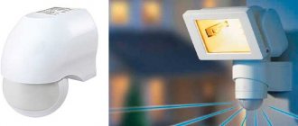
- lamps equipped with motion sensors. These types of devices work effectively near structures - garage doors, central and back entrances to the house, veranda, etc. Activation occurs when movement appears within range;
Light with motion sensor
Astronomical relay
- astronomical relay. This type of equipment is used to solve certain problems. A special feature of such relays is that they are programmed by coordinates. There is no need to install the sensor itself on the plot. This device is capable of independently calculating the time of sunset and dawn, as well as the time of year, thanks to which it can effectively turn on the light automatically at the right time;
- relays with a delay function for turning off the light. Such devices can be controlled by push-button switches and can also be turned off after a programmed time.
Any type of equipment that operates in automatic backlight mode can be easily installed with your own hands. To connect here you only need the diagram supplied by the manufacturer.
Master light switch: technical implementation
There are 3 key decisions regarding technical implementation.
- The contactor and master button are installed in the electrical circuit that powers the lighting group.
Before installation, it is better to have a schematic diagram before your eyes. When you press the switch button, the contactor supplies power from the group circuit where the apartment's lamps are connected. This is the most popular option.
- Centralized switching on and off of lights.
Lighting is controlled using a master switch if the entire lighting network in the house is mounted on pulse relays. This option is more expensive and complex; additional special modules are used.
Centralized turning on and off of light in the presence of a pulse relay Source uk-parkovaya.ru
- The most functional and universal solution.
With this option for connecting the master switch, a PLC (programmable logic controller) is used. Thanks to programming, it is possible to change the lighting scheme. Depending on the selected equipment, it is possible to reduce the cost of this option compared to the cost of pulse relays.
Automatic lighting switch based on PIR
I would like to share my experience in using professional pyroelectric passive infrared (PIR) sensors. We are talking about sensors that are used in security alarm systems. I have been using these sensors for a long time to automatically turn lights on and off. You may ask - why all this fuss, if a similar sensor for household use can be freely purchased in a store? There are reasons, of course, and even several of them. Those who have already had experience using such household sensors know very well that the quality of their work, and the quality of how they are made, is very often, as they say, “below the plinth.” I won’t say that they are all like this, but when buying them you need to realize that you are buying a “pig in a poke”. In my personal practice, I had the experience of purchasing a similar household sensor... I was then forced to spend another three days to bring its operation “to mind.” The second serious drawback is that due to the peculiarities of their circuitry, most of them are not capable of turning on a load with a power of less than 60 W. And this is a very big drawback. I will explain why this is so later. It’s also very bad that they do not have galvanic isolation from the 220 Volt network, which is bad in any case.
It is for these reasons that I only use professional sensors. It should be especially noted that these sensors are available for free sale, and their prices are comparable to household sensors. Professional sensors are reliable by definition, and the quality of their work never causes problems.
Obviously, a person who is not friendly with electricity will not be able to use this sensor. But with even a little experience working with a soldering iron, you can do it. There is nothing special to explain about the practical benefits of the machine, which turns on the light wherever you appear, this is already understandable. But the positive emotions that it evokes simply cannot be expressed in words - after installing the first machine, for a whole year I wanted to bow as a sign of gratitude when, upon entering the hallway, the light suddenly turned on. Now it has been a long time since the lighting of the kitchen tables, the light in the toilet, the bathroom, the corridor turn on themselves. You get something a la “smart home”, but, however, without the “brains” yet.
Within the framework of this article, we will not go into detail into the very principle of operation of the sensor - a lot has already been written about this. Let it “gurgle” there, something like that... Another thing is important for us - to make the sensor turn on the light.
We will slowly move towards the goal, and by the end of the story, it will become clear that now everything is clear.
Let's start with the sensor itself, naturally. I won’t tell you what it looks like – everyone has seen it. Another thing is important - inside, we will find a board with a terminal block with signatures - +\- 12 V and symbols of the contacts of a normally closed relay. Two things are immediately clear - you will need a 12 Volt power supply (we’ll talk about it in more detail later; what it should be like depends on what else you will power it with)... and the fact that we cannot immediately use the standard relay contacts. Well, it’s a sensor – it’s also a sensor in Africa, its job is to issue commands. And the contacts of its relay work like this - when there is no movement in front of the sensor, its contacts are closed, and they break only for a few seconds , at the very moment the sensor is triggered (when it “sees” movement).
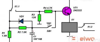
To directly turn the light on and off, there will be another block - let's call it - timer . The principle of its operation will become clear if we look at its diagram.
The timer circuit itself is so simple that I never even made a board for it, but mounted all the elements directly on the relay terminals. The logic of the timer is very simple.
In the absence of movement, the motion sensor relay contacts are closed. The anode potential VD1 is zero. Capacitor C1 is discharged (through resistor R2), the field-effect transistor is closed, relay P1 is turned off. When the sensor is triggered, the sensor relay contacts briefly , while capacitor C1 is quickly charged through the circuit - +12V_resistor R1_ diode VD1_ - 12V. In this case, transistor T1 turns on relay P1. Then the contacts of the sensor relay close again, and capacitor C1 begins to slowly (about four minutes) discharge through resistor R2 (through the closed contacts of the sensor relay, C1 cannot discharge - this is prevented by the locked diode VD1).
The trick is that if during these four minutes the sensor notices even the slightest movement, capacitor C1 will again charge to the maximum, and the countdown of the four-minute time period will begin again. In other words, the light in the room will not go out until the motion sensor “sees” that there is movement in the room. The lights will go out only four minutes after everyone has left the room. The exposure time can be changed by changing the values of C1 or R2, but practice has shown that four minutes is quite enough; of course, you can sit for four minutes without moving, but you have to try hard.
I hope everything is clear about the principle of operation itself. It remains to talk about all the nuances of use.
The figure below is a diagram for switching on a 220 Volt load. Let me explain the purpose of the “duty light” option. The practice of using an automatic light switch, for example, in the bathroom, has shown that entering it is much more comfortable when it is twilight rather than complete darkness. This emergency lighting is provided by the always-on LED HLds (only one LED is enough). It consumes only 180 mW, but significantly increases comfort.
Below is a diagram for switching on a 12 Volt LED lamp (I will explain below how to make a lamp).
The timer circuit board might look like this:
But it would be advisable to adjust it to the relay that you plan to use.
Details about the 12 Volt power supply. It is better to use it already ready, from some modem, for example. Its power should, as a rule, not be great. Let's estimate - the motion sensor itself consumes only 20 mA, plus the timer - 50-60 mA, that is, without an LED lamp, a very low-power power supply unit, designed for a current consumption of 100-200 mA, is sufficient.
If you power the LED lamp itself from the power supply, then the main current will be consumed by the LED lamp itself, in this case, a 12 Volt power supply with a maximum current of 1 Ampere should be enough for you. It is easier to use a ready-made power supply than to assemble it yourself. But decide for yourself what is more convenient for you.
It’s quite easy to make an LED lamp yourself, from pieces of LED strip. I won’t tell you in detail how to do this - everything is obvious in the photo below. I use it to illuminate the cutting table in the kitchen.
It is convenient to supply power to such a machine in the place where the light bulb socket was previously connected. This will allow you to use the standard switch. When leaving for work, you turn off the lights as usual, and the machine is completely de-energized.
Make yourself such a machine, and it will provide comfort to you and your loved ones for many years. I assure you that for a long time you will be asking yourself the question - why didn’t I do this earlier?
Note
Some of the professional sensors, after applying power, perform self-diagnosis, therefore, the first command may appear with a delay of 15-20 seconds. This is normal operation of the sensor and should not be taken as a sign of abnormal operation.
Let me remind you that you also need to choose the right location for the motion sensor itself. If possible, he should always “see” you, no matter where you are in a given room.
And one more piece of advice - if you plan to place two LED lamps on your kitchen set, it is advisable to make them at the same time, and from the same LED strip. The reason is simple - all LEDs are slightly different in their emission spectrum, and if you make lamps at different times and from different LED strips, then there is a high risk that the shade of white light will be different, which is very noticeable. And the LED strip must be purchased with a “reserve” so that when individual LEDs fail (which happens once a year), there is something to replace them with. It is advisable to use tape for lamps without a plastic coating. This will greatly facilitate subsequent repairs of lamps.
Also, just two words about the field-effect transistor VT1 in the timer circuit - my choice indicated in the list may seem strange, but the reason is simple - you can install almost any one with an N-channel, which is at hand and which you don’t mind. It is only important that it has a really high source-gate resistance (without built-in resistors and protective zener diodes).
List of radioelements
| Designation | Type | Denomination | Quantity | Note | Shop | My notepad |
| VT1 | MOSFET transistor | FDD8447L | 1 | Or 2N7000 | Search in the Otron store | To notepad |
| VD1ь VD1 | Rectifier diode | 1N4148 | 2 | Search in the Otron store | To notepad | |
| R1 | Resistor | 12 kOhm | 1 | 0.125 W | Search in the Otron store | To notepad |
| R2 | Resistor | 470 kOhm | 1 | Search in the Otron store | To notepad | |
| C1 | Electrolytic capacitor | 220uF 25Volt | 1 | 2 | Search in the Otron store | To notepad |
| P1 | Relay | HJR-3FF-SZ | 1 | 12VDC | Search in the Otron store | To notepad |
| Add all | ||||||
Attached files:
- Timer DD_180714.lay (270 Kb)
Tags:
- PIR sensor
- Sprint-Layout
Placement of master switches and non-switched lines
System devices are usually located near the entrance to apartments, in the bedroom or office. These are places where it is more convenient to turn off all lighting devices, as well as centrally control the curtains.
To install non-switchable lines in the electrical panel, a switch or load switch is used to control switchable circuits. This solution is found everywhere.
Advantages of circuit breakers relative to master switches:
- simplicity;
- reliability;
- durability;
- compactness;
- low price.
Disadvantages of switches:
- not convenient to use, unlike master switches;
- non-switchable circuits require additional lighting installation;
- To ensure that devices are turned off and current is regulated, operations are performed manually.
The switch is built into the electrical panel Source grand-electro.ru
Additional lighting is done along the entire line to the electrical panel so that there are no problems in the dark when the lights are turned off throughout the house);
Master Button is a universal solution; it has everything you need. Without going to the switches located throughout the apartment, the device immediately turns off the lights everywhere.
Whether to install master switches or circuit breakers depends on the needs of the residents. The choice is influenced by the advantages and disadvantages of the devices.
Organization options
Today, the variety of automatic devices designed to control street light is quite large. Today the following devices can be used:
- infrared switches. The principle of their operation is similar to the functioning of motion sensors. They can be used over the relatively short distance that exists between the transmitter and receiver;
- radio controlled switches. Such products can be placed at a much greater distance, unlike infrared models. This distance can be 100 meters or more.
Radio controlled switch
Both of these devices operate on the principle of remote control. Their design includes a receiver and transmitter. At the same time, they can provide control of several electrical loads simultaneously. At the same time, such devices are somewhat inferior in efficiency and comfort to devices operating in automatic mode. This is due to the fact that human presence is required to activate them. Therefore, today the most popular is a special unit for turning on and controlling light. Such modern models of modular equipment make it possible to:
- program devices for a certain time when it is necessary to turn on the external lighting;
- create various combinations with other devices for unique and inimitable illumination of certain areas (for example, lawn, flower beds, verandas, etc.).
Using modern devices that operate in automatic mode, you can significantly increase the efficiency of street lighting, making it more convenient for yourself.
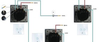
How to connect a pass-through switch
Pass-through switches are used at the beginning and end of the electrical circuit, and a crossover switch is used in the middle of the line. There are other solutions, but less often.
The advantage of control circuits based on pass-through switches: simplicity and reliability. Flaws:
- it is impossible to automate the lighting control system;
- you cannot change the scheme after some time;
- cable consumption is high.
Sometimes a control scheme is implemented for 2 groups of lighting fixtures from N-places on 2-key pass-through elements. However, such a scheme is cumbersome and inconvenient in everyday life. Such switches do not have a fixed “On” or “Off” position.
Connection diagram for pass-through switch Source yandex.ru
How to connect a switch with one key
The cartridge has 2 terminals; one of the cable cores is inserted into each connector and secured with a clamping screw, then the switch is connected. To do this, the device is disassembled with a screwdriver or by hand: the key attached to the plastic latches is disconnected. If it does not snap off, you need to push it from the back side. After unscrewing 2 screws, the decorative cover is removed.
The connection diagram boils down to the fact that you need to install a single-key switch in the “phase” break.
Connection diagram for a three-key switch Source svetosmotr.ru
Connection diagram
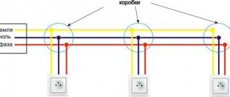
There are two ways to connect sockets: from the electrical distribution box in a house or apartment, or using a cable (in this case, the subsequent device is connected from the previous one). Direct connection from the junction box is considered the main and most reliable method.
When drawing up an installation plan for the electrical wiring of a room (apartment, cottage), it is advisable to connect all single devices and their units to the junction box directly. This is especially true for blocks. An exception can be made for nearby single sockets with a distant distribution box.
Attention! Common colors of wires in household electrical wiring: blue - zero (zero working), white, black, brown, gray or red - phase, yellow-green - neutral protective (grounding conductor).
Useful tips Connection diagrams Principles of operation of devices Main concepts Meters from Energomer Precautions Incandescent lamps Video instructions for the master Testing with a multimeter
How to connect a three-key switch
Connecting a 3-key switch is done in exactly the same way as one and 2-key switches. The difference is in the number of contacts of the outgoing groups: 1, 2 or 3. One supply cable is connected to the input terminal of the switch, and the wire of the lamps is connected to the “output” contacts. The neutral conductors of all lighting devices are combined into one circuit and connected to the “zero” in the box.
Connection diagram for 3-key switch Source vodakanazer.ru
General principles for installing light switches
Installation of a simple lighting system and control devices is carried out during renovation work in the room. For hidden wiring, before finishing finishing work, the cable is laid in grooves and places are prepared for the installation of switches. In this case, switching of switches, lighting devices and power lines is carried out in installation junction boxes. Such boxes can be located in special niches in the walls, hidden in the floor or behind a suspended ceiling.
In some cases, for example, in wooden houses, the installation of hidden wiring is prohibited by regulations, so in such rooms installation is carried out openly after finishing the room (using cable ducts or special corrugated tubes).
The general principle of connecting switches is in most cases the same: the switch serves to break the phase on the line, and the zero is connected directly to the lamp. Why phase and not zero? This requirement is directly stated in the PUE, which states that the possibility of breaking one neutral conductor without disconnecting the phase conductor must be excluded. This is directly related to safety measures when operating lighting devices. When a device is disconnected from the mains using the switch, there must be no voltage applied to it so that it can be safely repaired or the lamp replaced.
Lighting control circuits through contactors and magnetic starters
To switch on contactors and magnetic starters, push-button posts are used. This is a device equipped with 2 buttons: “Start” and “Stop” or 3: “Forward”, “Stop”, “Back”. These elements are without fixation, with closed and open contacts.
The lighting control circuit is simple and is shown below.
Magnetic starter connection diagram Source uk-parkovaya.ru
