Electrical energy on an industrial scale cannot be transmitted in the form of single-phase alternating current. For this purpose, three-phase current is used, and three-phase transformers are used for its transmission. One of the ways to transform three-phase current is the use of three single-phase transformers.
The connection of the primary and secondary windings in these devices is carried out in one of the three-phase systems - star or delta. It is on this principle that powerful single-phase transformers operate, which are equipped in large power plants. Their primary windings are connected to the corresponding phases of the generators, and the secondary windings, connected in a star, are connected to the corresponding phases of the power lines.
Operating principle of a three-phase transformer
As can be seen from the diagram above, instead of three single-phase devices, one three-phase transformer can be used. Its magnetic circuit consists of three rods, which are closed by yokes at the top and bottom. A primary and secondary winding is wound on each rod, then connected by a star or triangle. Each rod with windings is essentially a single-phase transformer. At the same time, it performs the function of a separate phase of a three-phase transformer.
Under the influence of the primary winding current, a magnetic flux appears in all rods. It is necessary to take into account the belonging of each such winding to one of the phases included in the three-phase system. Therefore, the currents flowing through these windings, as well as the applied voltages, are three-phase. Therefore, the generated magnetic fluxes are also three-phase.
Previously, it was believed that the movement of the magnetic flux occurs along a closed path, that is, passing along the rod, it returns to its beginning. In three-phase transformers there is no such return path; it is simply not necessary, provided the phase loads are the same. In addition, there is no need for a neutral star connection.
Conditions for parallel operation of transformers.
Most transformers supply consumers in parallel groups. To be switched on for parallel operation, transformers must have: identical transformation ratios . Otherwise, an equalizing current will circulate between their secondary windings, which, even with a small difference in transformation ratios, can lead to dangerous overheating; identical short circuit voltages uk, %, otherwise they will not be able to share the load in proportion to their powers 1. In other words, some transformers will be underloaded, others will be overloaded; identical connection groups . If the connection groups are different, then a phase shift is formed between the corresponding vectors of secondary voltages of transformers connected in parallel. It will entail a voltage difference. And since different voltages cannot exist at the same point at the same time, an equalizing current will arise between the transformers to equalize them. As explained below, at the smallest possible offset (with different connection groups) - an offset of 30° - the equalizing current is approximately 5 times the rated current of the transformer. At the largest shift - 180° - 20 times.
How three-phase current is transmitted
The primary power source in most cases is the electrical network. Its voltage is presented as a sinusoid with a frequency of 50 Hz. However, in cases where power transmission lines are long, the transmitted energy is radiated into the surrounding space, which leads to additional losses. Therefore, three-phase voltage is used in high-power power supply circuits.
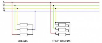
In order to reduce radiation, the sum of the voltages on all three phases must be zero at any time. For this purpose, the sinusoidal voltage is shifted in phase in each wire relative to each other by 120 degrees. In this state, the transmission of electricity can be carried out in two ways: using four or three wires of the transmission line. Conditional diagrams of each option are shown in the figure.
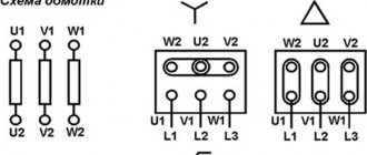
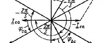
The four-wire line allows you to supply the consumer with two types of voltage: phase (220 V) and linear (380 V). The three-wire circuit allows you to output only linear voltages. The formation of linear voltage is described using a vector diagram of phase voltages. With a positive phase alternation, they conditionally increase clockwise. To connect the windings of three-phase transformers, two main methods are used - star and delta.
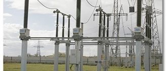
Maintenance and repair
The operation of the devices is associated with high power values
Therefore, increased attention is paid to their maintenance. Maintenance personnel perform daily inspections and monitor readings of measuring instruments.
During the maintenance process the following indicators are assessed:
- The degree of depletion of the device that absorbs moisture.
- Amount of oil.
- Wear of oil regeneration mechanisms.
- Presence of leakage, mechanical damage to radiator pipelines and housing.
If the facility does not provide for round-the-clock personnel duty, periodic audits are carried out once a month. At transformer points, inspections are performed once every 6 months.
If necessary, change or add oil. Its color is controlled by visual inspection. If it becomes dark, it is changed. Once a year and during major repairs, a laboratory study of the oil composition is performed.
To destroy the oxide film on copper and brass elements, disconnect the unit from the power supply once every 6 months. The switch is moved through all positions several times. This procedure is carried out before seasonal load fluctuations.
Power equipment is an important element of the power supply network
They operate around the clock, so it is important to pay attention to the features of their selection and maintenance. This is one of the most complex but extremely important devices
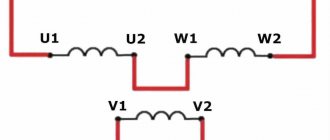
Star connection
It is recommended to consider this type of connection using the example of a star-star circuit. In this case, the current source and load are connected using the star method.
In the figure, the designation of phase voltages generated by the secondary windings of the transformer is indicated by the symbols UA, UB, and UC. From the phase windings to the load there are conductors that perform the function of linear wires. It is necessary to take into account the presence of voltage not only between the neutral and linear wires, but also between two linear conductors. This voltage is called linear and is designated UAC or UCA.
The line voltage value always exceeds the phase voltage. The difference between them is √3 times, since it represents the vector difference of the phase voltages. Thus, a three-phase power line allows you to receive not only 380 V, but also 220 V, depending on which circuit the load is connected to.
Classifications
Transformers are classified according to a number of parameters, such as:
- Purpose. Used: for changing voltage, measuring current, protecting electrical circuits, as laboratory and intermediate devices.
- Installation method. Depending on the location and mobility, the transformer can be: stationary, portable, internal, external, support, busbar.
- Number of steps. The devices are divided into single-stage and cascade.
- Rated voltage. There are low and high voltage.
- Winding insulation. The most commonly used are oil-paper, dry, and compound.
In addition, converter devices come in different types, each of which has its own classification system.
Power
The most widely used type is the power transformer. Devices with direct conversion of alternating voltage, designed for high power, are in demand in various areas of the electric power industry. They are used on power lines with voltages of 35–1150 kV, in city power networks operating with voltages of 6 and 10 kV, and in providing end consumers with voltages of 220/380V. The devices provide power to all kinds of electrical installations and devices in the range from fractions to hundreds of thousands of volts.
Power transformer
Measuring
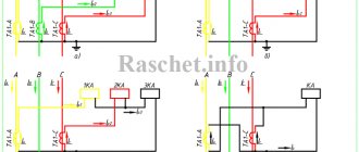
Current transformers (CTs) reduce the current to the required levels. The scheme of their operation is distinguished by the sequential connection of the primary winding and load. At the same time, the secondary winding, which is in a state close to a short circuit, is used to connect measuring instruments, actuators and indicator devices. With the help of TA, galvanic isolation is carried out, which makes it possible to avoid using shunts during measurements.
High voltage CT(left) and low voltage CT(right)
With the help of voltage transformers (VT), the same as TA only in voltage. In addition to converting input parameters, electrical equipment and its individual elements are protected from high voltage.
High voltage transformer (left) and low voltage transformer (right)
Pulse
If it is necessary to convert pulsed signals, pulse transformers (IT) are used. By changing the amplitude and polarity of the pulses, the devices maintain their duration and practically do not affect the shape.
Autotransformer
In autotransformers, the windings form one circuit and interact through electromagnetic and electrical communication. Unlike other types of converters, devices can contain only 3 outputs, allowing you to operate with different voltages. The devices are distinguished by their high efficiency, which is especially noticeable with a slight difference in input and output voltage.
Single-phase (left) and three-phase (right)
Without galvanic isolation, representatives of this type increase the risk of high-voltage shock to the load. A prerequisite for the operation of devices is reliable grounding and a low transformation ratio. The disadvantage is compensated by lower consumption of materials during manufacturing, compactness and weight, and cost.
Dividing
For isolation transformers, interaction between the windings is eliminated. The devices increase the safety of electrical equipment in the event of damaged insulation.
Isolation transformer
Coordinator
Matching transformers are used to equalize resistance between stages of electronic circuits. While maintaining the signal shape, they play the role of galvanic isolation.
Peak transformer
Using a peak transformer, sinusoidal voltage is converted into pulse voltage. In this case, the pulses change polarity with each half-cycle.
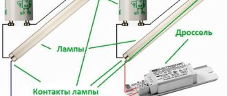
Twin throttle
A feature of a dual inductor is the identity of the windings. The mutual induction of the coils makes it more efficient than standard chokes. The devices are used as input filters in power supplies, audio and digital equipment.
Twin throttle
Welding
In addition to the above, there is the concept of welding transformers. Specialized devices for welding work lower the voltage of the household network while simultaneously increasing the current, measured in thousands of amperes. The latter is adjusted by dividing the windings into sectors, which affects the inductive reactance.
Welding transformer
General structure and principle of operation
Let's consider the design of a simple transformer with two coils mounted on a closed magnetic circuit (see Fig. 2). The coil that receives current will be called the primary coil, and the output coil will be called the secondary coil.
Figure 2. Transformer design
Virtually all types of transformers use electromagnetic induction to convert the voltage entering the primary winding circuit. In this case, the output voltage is removed from the secondary windings. They differ only in shape, magnetic core materials and methods of winding the coils.
Ferromagnetic cores are used in low-frequency models. The following materials are used for such cores:
- steel;
- permalloy;
- ferrite.
In some high-frequency models, magnetic cores may be absent, and in some products materials made from high-frequency ferrite or alsifer are used.
Due to the fact that the characteristics of ferromagnets are characterized by nonlinear magnetization, the cores are assembled from sheet materials onto which windings are placed. Nonlinear inductance leads to hysteresis, to reduce which the method of lamination of magnetic circuits is used.
The core shape can be W-shaped or toroidal.
Figure 3. Transformer appearance
Basic principles of operation
When a sinusoidal current is supplied to the terminals of the primary windings, it creates an alternating magnetic field in the second coil that penetrates the magnetic circuit. In turn, a change in the magnetic flux provokes the induction of an emf in the coils. In this case, the magnitude of the EMF voltage in the windings is proportional to the number of turns and the frequency of the current. The ratio of the number of turns in the primary winding circuit to the number of turns of the secondary coil is called the transformation ratio: k = W1 / W2, where the symbols W1 and W2 indicate the number of turns in the coils.
If k > 1, then the transformer is step-up, and if 0 < k < 1, then the transformer is step-down. For example, when the number of turns that make up the primary winding is three times less than the number of secondary turns, then k = 1/3, then U2 = 1/3 U1.
Operating modes
The power transformer can operate in three modes:
- in idle state;
- in load mode;
- in short-circuited mode.
Since there is no current in the open circuit of the secondary winding, in this state no-load current circulates through the primary winding. The parameters of this current are used in efficiency calculations, the transformation ratio is determined, and losses in the core are found.
The main operating mode of the transformer is the state when the rated load is connected to its second winding. The primary current can be expressed through the resultant no-load current and the calculated load resistance current.
In short circuit mode of the secondary winding, all power is concentrated in the winding circuits. In this state, it is possible to determine the losses spent on heating the wires in the windings.
A little bit of history
The invention of transformers began back in 1876 by the great Russian scientist P.N. Yablokov. His product did not have a closed core; it appeared later - in 1884. And with the advent of the device, scientists became actively interested in alternating current.
For example, already in 1889 M.O. Dolivo-Dobrovolsky (Russian electrical engineer) proposed a three-phase alternating current system. He built the first three-phase asynchronous motor and transformer. Two years later, a presentation was made of a three-phase high-voltage line with a length of 175 km, where electricity was successfully increased and decreased.
A little later, oil units appeared, since oil not only turned out to be a good insulator, but also an excellent cooling medium.
Quick comparison table
Both options are used in the electrical field. These are proven winding systems that help maintain power while also reducing wear.
It is better to compare schemes using the same properties - it becomes clearer why one should choose one or another option.
| Criterion | Star | Triangle |
| Voltage | 330 V | 220 or 380 V |
| Number of output wires | 3 | 6 |
Expert opinion
Karnaukh Ekaterina Vladimirovna
Graduated from the National University of Shipbuilding, majoring in Enterprise Economics
There is an alternative option when the circuit combines both types of winding. That is, there is a switch from star to triangle or vice versa. This technique is suitable for phase motors with a starting rotor.
What are the differences
The main difference between the types of windings is the way they achieve and obtain different parameters of electrical voltage and current inside the motor. The first case involves a gradual increase in performance, the second option provides powerful current transmission.
The triangle and star methods differ in the implementation of the task. Often electricians use a combination of circuits. This gives a gentle mode for the wire or transformer, but at the same time the current takes on a smaller value.
Expert opinion
Karnaukh Ekaterina Vladimirovna
Graduated from the National University of Shipbuilding, majoring in Enterprise Economics
The triangle system, as a rule, is acceptable when connecting powerful mechanisms and the presence of large starting loads. If in this case you use a star rather than a triangle, you can cause damage to the engine. This is where the types of windings differ from each other.