Capacitive photo relay for street lighting is a device that allows you to turn on or off lamps used on roads, at entrances and in parks. Their use saves energy and minimizes inconvenience for drivers, home residents and ordinary passers-by.
The work is based on a photoresistor or photodiode - semiconductor elements that change their parameters depending on the intensity of ambient light. During the day, when there is sufficient light, the light sensor opens the circuit and the lamp turns off, and at night the reverse sequence of actions occurs: the capacitive relay for controlling the lighting reduces the resistance and the light turns on.
Installation of photo relay
It is not difficult to install a photo relay with your own hands; it is only important to exclude the direct influence of the adjustable light source and protect the device from adverse external influences: moisture, direct sunlight, temperature changes.
For industrial devices, there are a number of standards that such solutions must comply with: GOST (domestic) and IP (international). It is more difficult to ensure that a homemade photo relay is protected from environmental factors, although it is theoretically possible. But for those who want to install such a device in their yard, near their entrance or garage, it is better to first consider the solutions offered on the market - without having the necessary knowledge and experience, it will be extremely difficult to bring the photo sensor to working condition with your own hands.
Astro timer
An astronomical timer (astro timer) is another way to automate street lighting. The principle of its operation differs from the photo relay, but it also turns on the light in the evening and turns it off in the morning. Light control on the street occurs according to time. This device contains data about what time it gets dark/light in each region in each season/day. When setting up the astro timer, the GPS coordinates of its installation are entered, the date and current time are set. The device works according to the programmed program.
Astro timer - the second way to automate the light on the site
Why is it more convenient?
- It does not depend on the weather. In the case of installing a photo relay, there is a high probability of false alarms - in cloudy weather, the light may turn on in the early evening. If the photo relay is exposed to light, it may turn off the light in the middle of the night.
- You can install the astro timer in your home, in a control panel, or anywhere. He doesn't need light.
- It is possible to shift the on/off time by 120-240 minutes (depending on the model) relative to the specified time. That is, you can set the time yourself as convenient for you.
The disadvantage is the high price. In any case, the models that are available in the retail chain cost quite a lot of money. But you can buy it in China much cheaper, although how it will work is a question.
FR-601 (602)
When it comes to using standard single-phase photo relays for lighting, the most popular model is the FR-601 and FR-602 devices manufactured by IEK.
They are quite reliable, and even users uninitiated in electronics have no questions about how to connect an automatic backlight controller. These two modifications have minor differences: they both operate with current of the same voltage and frequency, have similar power consumption (0.5 W) and absolutely identical delivery kits.
The differences relate only to the maximum cross-section of the connected conductors: for the 601 model it is 1.5 square meters. mm., and for 602 - 2.5. Consequently, their rated load current is also different: 10 and 20 A, respectively. Both models have a built-in photocell; it can be adjusted from 0 to 50 lux in increments of 5 lux.
Principle of operation
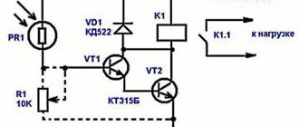
First, let's talk about how this device generally works. The design includes simple elements: a photocell, a phototransistor, a comparator and a relay.
The main task is to monitor the light intensity and, if something happens, close the circuit. As soon as the light intensity decreases, the photocell reacts to this, and it notifies the comparator, which has a response threshold, about this. If the voltage is higher than the set one, a relay is connected and turns on the lamp. Find out how to connect outdoor lights.
How a photo relay works: video
Making at home
The schematic diagram of the FR-602 capacitive photorelay (like its brother) is easily repeated even with little knowledge of electronics. Creating a homemade product becomes especially relevant when there is a need for a large number of devices (for example, to organize automatic switching on and off of lighting depending on the time of day).
For manufacturing you will need the following parts; the designation on the diagram and power will be indicated in brackets:
- 2 bipolar transistors BC857A (Q1 and Q2);
- 5 rectifier diodes 1N4007;
- rectifier diode 1N4148;
- Zener diode 1N4749;
- resistors (R2, R4–R9: 1.5 MΩ, 1 MΩ, 560 kΩ, 200 kΩ, 100 kΩ, 75 kΩ and 33 kΩ; all 0.125 W);
- resistor (R3, 220 Ohm, 2 W);
- photocell (PH, up to 100 kOhm);
- trimming resistor (WL, 2.2 mOhm);
- capacitor (C2, 0.7 µF 400 V);
- electrolytic capacitors (C4–C5, 100 μF 50 V and 47 μF 25 V, respectively);
- relay SHA-24VDC-SA (Rel1).
Considering the set and total cost of parts, as well as the availability of a diagram, model 602 is a fairly simple solution to implement.
By the way, many parts from the list can be replaced with domestic ones. According to reviews from those who have already assembled, the bipolar transistor Q2 can be replaced with the ubiquitous KT3107B, and the zener diode 1N4749 can be replaced with three series-connected D814A or two D814D. The connection diagram is also not particularly complicated.
Connection features
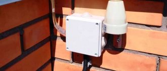
Correct installation location
A photo relay is usually located near the light source, the operation of which it must regulate. This is especially true for outdoor type meetings.
Note! In order for the sensor to work as it should, when connecting it, you need to prevent light from the lamp from reaching the photocell. It would be best to place the device in the shade of a lighting fixture.
Three wires come out of the street lighting sensor housing. They need to be connected correctly to the lamp:
- blue conductor. It is intended for zero. In addition, it is possible to connect a conductor from a lighting device to it;
- brown conductor. This conductor is necessary to connect to the mains power phase;
- red conductor. The sensor is controlled through it. It leads to the lamp from the existing regulator.
In rare cases, which is sometimes typical for a street lighting system, the sensor design requires the presence of an additional conductor - “ground”. With its help, you can prevent voltage from entering the device body. In this situation, the circuit for connecting the photo relay to street lighting will be standard. But the “ground” will be connected to the lamp itself, bypassing the regulator.
Note! Some manufacturers change the markings of conductors.
Therefore, a basic connection diagram is used:
- the phase is always connected to the regulator;
- zero is connected to the regulator and goes to the lamp;
- the phase goes from the regulator to the lamp.
Now, knowing how the photo relay is connected, you see that it will be quite easy to do everything yourself.
Analogs
Among the analogues of this device are the FR-75A - a photo relay, the circuit of which is more complex for manufacturing at home, and is also less stable and durable in practical use.
Among its advantages is a larger range of operating brightness, ranging from 1 to 200 lux, which is four times higher than its competitor. Another big advantage of the FR-75 device is the ability to operate in 12 V DC circuits.
Also, the photosensor is remote, which allows you to install the regulator itself indoors and not worry about environmental factors. In general, the model has no equal in its class and is the best photo relay - 12 volts DC is often used as power for such devices. The device connection diagram is shown in the figure.
How the device works
So, first let's look at how the twilight switch works so that you understand the features of its connection, which we will provide below.
The design of a photo relay includes three main elements: a photocell, a comparator and a relay.
As for the photocell (and basically it is a photodiode, phototransistor or photoresistor), its main purpose is to analyze the light intensity. If it gets darker or brighter outside, the photocell will let you know about it, and the light will turn on/off on the basis of this. The comparator is the so-called threshold of the system. If the voltage supplied by the photocell exceeds the setting, the comparator will turn on the relay, and accordingly the lamp. A relay (or triac) is an output device that switches a load (in our case, a light bulb).
Simply put, the principle of operation is this: when the lighting level decreases, the resistance on the photoresistor changes, as a result of which the voltage increases and the relay operates. The result is that the lamp to which the device is connected turns on until it begins to get light.
Video review of the detector from Feron, model SEN27:
Device characteristics
High power equipment
Among the competitors, you can also consider the FR-7E photo relay, but the lack of moisture protection (IP40) and rather high power consumption are not in its favor.
Disadvantages also include open contact clamps and lack of protection for the trimming resistor on the front panel. A positive point is that the FR-7 can operate in AC networks of 220 volts with a voltage of up to 5 amperes, which is almost an order of magnitude greater than that of the competitors discussed above. The adjustment range of 10 lux is also set only by a specialist; you cannot adjust it yourself.
In terms of dimensions, the FR-7 also exceeds the photo relays discussed in the article (see drawing).
Scope of application
The use of photo relays is not limited to street lighting. With a little imagination, it can be used in other places, here are some examples:
- Garage. It is very convenient when, when you open the garage door from the outside, the light will turn on automatically and you do not need to feel for the switch. True, this is more relevant in city garages, where the light outside is constantly on. For country houses, this scheme will only work during the day.
- Irrigation control. Another interesting application of a photo relay is the activation of drip irrigation at night. An excellent solution for summer cottages and private houses, which will significantly save your time during the daytime. Whether it’s a lawn or flower beds, everything will be thoroughly moistened overnight without your intervention. But here you need to monitor the weather and turn off the system on rainy days.
Recently, a system called “Smart Home”, where complete automation reigns, has become increasingly popular. So, the photo relay occupies an important place in it, being used in conjunction with motion sensors and other “smart” devices.
Where can I buy
If you want to save time, you can purchase the necessary device at your nearest specialty store. The optimal option, in terms of price-quality ratio, remains purchasing from the AliExpress online store. Mandatory long waits for parcels from China are a thing of the past, because now many goods are in intermediate warehouses in destination countries: for example, when ordering, you can select the “Delivery from the Russian Federation” option:
| Photo relay with automatic on/off | Photosensitive module for Arduino | Automatic control module for light switching |
| Street lamp with built-in light sensor | Adjustable photoresistor switch | Wall switch for lighting control |
Connection procedure
Often, photocell sensors are attached to walls using special brackets. They must come with the purchased model. To correctly connect a photo relay to automate street lighting, you need to do the following:
- a connection diagram is usually placed on the device body, which should be studied in detail;
- After you have familiarized yourself with the diagram, you need to choose a suitable location for installation. We talked a little higher about what requirements the installation site must meet;
- connect the wires coming from the bottom of the sensor housing to the lighting fixture;
- after that we set up the photo relay. First, we set the response threshold. To do this, move the regulator to the position we need;
- If you install sensors with an external photocell, do not forget to connect them together using a cable after installation.
If there is a timer in the design of the device, the connection can be made through it. To do this, the timer should be programmed to operate at certain time intervals. This system is very beneficial and convenient for the daylight hours. Thanks to this connection method, quite significant energy savings can be achieved.
Note! The timer has its own memory, which is designed for different periods (from 1 to 12 months). Using a timer can significantly improve the operation of the sensor, making it more correct taking into account the length of daylight hours.
Advantages and disadvantages
The photo relay is practical for various objects requiring lighting control. The device allows you to save energy costs by turning off the lamps at the right time. This is the main advantage of the element. It is also worth considering easy installation, the ability to connect several lights to one sensor and simple operation. The presence of a timer and motion sensor makes the device more functional. During use, the sensor does not require constant attention
To get all the benefits, it is important to install the photo relay correctly and choose a quality element
The device with a timer is very convenient
A photo relay is an element of an outdoor lighting electrical circuit. Therefore, correct installation is required when connecting. Otherwise, malfunctions, breakdowns and malfunctions will occur, which will lead to additional costs.
And it is also important to choose a photosensor that matches the characteristics of the lamps and the required level of functionality
Video recommendations allow you to more effectively master the features of choosing and operating photo relays. The following video presents a simple device that is effective for private use.
Video: principle of selection and operation of photo relay
Lighting control using a photo relay is an effective way to reduce energy costs for illuminating a street or other objects. The sensor, whose parameters match the needs, is easy to install and has a number of advantages. And knowledge of the principle of operation of the device will allow you to make the right choice.
To control the operation of many electrical devices, special controllers are required, which are responsible for the accuracy and correctness of their operation. We propose to consider how to connect a simple street photo relay, what it is and its operating principle.
Possible malfunctions of the street lighting mechanism
If the photo sensor does not work correctly, the reason most often lies in installation or configuration errors.
First, make sure that there is no street light or high fence in front of the day-night device, maybe the tree has become much taller since installation, or has begun to shade the area more when leaves appear on it. Such obstacles must be removed or the photo relay moved to a more suitable location.
It is also possible that one of the residents of the house accidentally changed the settings, or they became irrelevant with the change of season. Monitor the set light sensitivity and set the response delay to at least 5 minutes.
If a motion sensor has recently been added to the system, a false activation may be due to the movement of pets or passers-by on the street.
Often a photo relay malfunction is determined visually
When simple methods do not help, you need to look inside the device. Perhaps moisture got into the case and the contacts oxidized, or as a result of a power surge in the network, one of the board elements burned out. If the damage is not too significant, you should take the device to a workshop and consult about repairs. But if the board is noticeably damaged, you will have to replace the device completely (or just the remote sensor). In a self-made device, you should first check the quality of soldering, and if necessary, replace the failed element.
When the device is fully operational and correctly configured, the reason may lie in the wires connected to it. Carefully check the integrity of the insulation in each section and, if necessary, replace the damaged cable.
If you cannot detect the fault yourself, you must contact the seller (if the device is under warranty) or a manufacturer’s representative.
Model type LXP. About the main technical characteristics
FR 601 are quite common devices that turn on and off depending on the level of illumination around. Street lighting fr 601 turns on as soon as it becomes dark outside. This solution increases the service life of any light bulbs and helps save energy.
The technical characteristics of device 601 will be as follows.
- <5 – 5o Lux. This is the performance designation for the 601 model.
- The 601 switched circuit operates up to 10 A.
- Variable voltage, requires a power source that supports 220 Volts.
At the bottom of the device, marked 601, there is a control that allows you to set the level for lighting under normal operating conditions. The level of light and the current strength of the switched circuit are the only fundamental differences between the models of this manufacturer.
Manufacturers with the designation 601 usually provide their own settings according to which adjustment and control are carried out. Therefore, it is imperative to study the technical data sheet of the lighting product before installation. The same applies to certification documentation and patent registration. Otherwise, due to mistakes, you will have to make major repairs to your apartment or house. It is better to install a separate machine on this controller, inside a distribution board or cabinet. The scope and brand determine how much a particular device will cost.