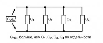
Homemade variable capacitor
Recently, it has become increasingly difficult to purchase variable capacitors.
I encountered this problem when creating a magnetic antenna: I was not satisfied with the high cost of vacuum capacitors, and I was not satisfied with the rusty appearance of used KPEs. In addition, KPIs from old receivers have a small gap between the plates and, when used in magnetic antennas, are pierced with high voltage. So I decided to make a homemade KPI. There were a lot of designs on the Internet, but the article that interested me the most was https://www.qsl.net/n4dfp/buildcaps.html. Actually, based on this article, the capacitor was made with minor modifications. So, the first thing we did was find a sheet of aluminum. It was found in a DIY store in the form of a sheet from a barrel of yogurt (0.3-0.4 mm thick). Blanks were cut from the sheet using scissors according to the drawings:
Drawings in SVG format can be downloaded from the link.
In total, 17 stator plate blanks were cut, and 16 rotor plates. All the plates were straightened, then 6 mm holes for screws were drilled in the right places. I recommend drilling workpieces of the same type at once, holding them in a vice. After drilling, the blanks were stripped of paint and the protective layer (the yogurt sheet was painted with advertising inscriptions on one side and a food layer on the other side). The end result was a bunch of stuff like this:
The side walls of the capacitor measuring approximately 100x70 mm were cut out of plastic.
To fasten the plates, I used M6 bolts 110 mm long, M6 nuts 4.5 mm thick, and washers.
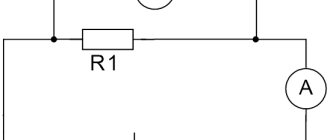
The fastening of the plates is shown schematically in the figure (side view):
The first stator plate is secured through 3-4 washers (depending on their thickness) to ensure the required gap between the rotor and stator plates, and is clamped with nuts. The first rotor plate is clamped with nuts on both sides, while a small gap is provided between the side wall and the fastener so that the bolt with the rotor plates rotates freely in the hole.
On the opposite side wall of the capacitor it is necessary to implement a current collector and a spring element. I combined the two functions into one using a curved plate made from the same aluminum sheet and a foam plastic sticker:
After assembly, we finally straighten the plates and achieve the same distance between the plates at any rotor position.
The result was a capacitor with a capacitance range of 7-330 pF. The materials cost less than $10.
Source
Superionistor service life
The elements under consideration have quite long service lives. For example, at a rated voltage of 0.6 V, the device can operate for up to 40,000 hours. During all this time, only a slight decrease in capacity will be observed. The expected service life depends on that declared by the manufacturer, but the impact of humidity, high voltage and temperature changes on the ionistor should not be excluded.
Important! Typically, the timing is based on ideal laboratory conditions.
Device marking and polarity indication
Thus, in this material it was explained how to make an ionistor with your own hands, and where it found its application. These elements, invented relatively recently, were discussed as a source of alternative energy and a breakthrough, but they did not become one. Despite this, their scope is very wide.
Homemade KPIs made from foil fiberglass
Variable capacitors, also known as variable capacitors or variable capacitors, are used in many devices. They are needed in generators, antenna tuners, some types of antennas, and much more. Let us pay attention to the fact that in amateur radio communications, for example, a transceiver can easily output 25 W or 100 W, but the maximum allowed power is 1000 W. It is clear that publicly available small KPIs are completely unsuitable here, and you simply won’t find the KPIs needed for such capacities in the store.
Suitable large KPIs from old radio equipment can be purchased on Avito and radio amateur message boards. But the prices there are often not low, the capacitors are rarely labeled with their capacity, it is not possible to find two or more identical capacitors, plus there are risks and inconveniences associated with buying them in person. Meanwhile, making a variable capacitor at home is not so difficult.
I got the idea from the 2003 article Build Your Own Transmitting Air Variable Capacitors by David Hammack, N4DFP. In his article, David uses copper sheets, which I did not have. But I figured that copper on a one-sided foil PCB, which I have in abundance, would work just as well. Why not try it?
I’ll show you right away what I ended up with. Front view:
The capacitor has five rectangular plates measuring 20 x 50 x 1 mm, secured with two long M3 bolts. The plates are separated by nuts. Four more semicircular plates with a radius of 25 mm are mounted on one M3 bolt. This bolt can be rotated using a potentiometer knob, which I glued to the bolt using epoxy glue. All this equipment is supported by a frame made of two rectangular pieces of sheet plastic measuring 30 x 50 mm. To connect to the moving plates I used thick copper wire bent into a loop. The wire fits tightly to the rotating bolt and is secured to the capacitor frame using hot-melt adhesive. The drop of solder, which can be seen in the second photo, serves to limit the angles of rotation of the handle. It is clear that everything would work without her. But I wanted the handle to have some extreme adjustments, and not just spin in all directions.
Fun fact! Textolite with a thickness of 1 mm can be cut with ordinary paper scissors. And the coil of solder standing on my table very fortunately turned out to be exactly 25 mm in diameter - I traced it around it.
The capacity of such a craft varies from 13 to 53 pF. By increasing the area of the plates or their number, you can get at least 1000 pF. I don’t think anyone will need larger capacitor trimmers. But such a capacitor will not be very convenient, both due to its large size and the fact that a slight turn of the knob will lead to a large change in capacitance.
A possible solution is to use the capacitor described above only for fine tuning, and use fixed capacitors for coarse tuning. The latter can be connected in parallel by switching toggle switches with two contact groups.
An example of a homemade fixed capacitance capacitor:
The capacitor consists of six plates 25 x 50 mm. The plates were glued together using epoxy glue. All even plates are connected to each other, and all odd plates are similarly connected. The capacitance of the capacitor is 270 pF. The practical value of such capacitors is apparently not very high, since high-voltage fixed-capacitance ceramic capacitors are readily available and inexpensive. However, let's look at them too, in case we ever need to work with very high voltages.
Fun fact! An alternative way to make a fixed capacitor is to simply take a piece of coaxial cable. A typical RG58 cable has a linear capacitance of about 100 pF per meter.
The dependence of the capacitance of the capacitor on the number of plates is as follows:
It can be seen that the capacitance increases in proportion to the number of dielectric layers up to the measurement error, which is in accordance with the theory. Using the first line, just for fun, you can calculate the dielectric constant of the PCB used:
This converges with an expected value of 4.4 to 4.7.
StackExchange suggests that to break through such capacitors, you need at least 3 kV per 1 mm of distance between the plates - this assumes that the current will flow through the air. To be on the safe side, it is recommended to use half of this value as the maximum voltage. The breakdown voltage can be increased by increasing the distance between the plates. But, as can be seen from the above formula, in this case the capacity will suffer, and the area and/or number of plates will have to be increased. A more practical solution is to etch 3mm of copper along the edge of the plates. Then the breakdown voltage will be about 20 kV - the breakdown voltage of 1 mm of PCB or 7 mm of air.
What the maximum voltage across the capacitor will be depends on the circuit in which it is planned to be used. This needs to be modeled or calculated every time. But in order for it to exceed the safe 10-15 kV, you will have to try. In this case, you can always simply increase the distance between the plates and use thicker PCB.
Fun fact! It goes without saying that there is nothing stopping you from delegating the manufacturing of capacitor components to your favorite PCB manufacturer.
As you can see, everything turned out to be quite simple. The obvious advantages of homemade KPIs are low cost and availability. You can make as many capacitors exactly as you need. As for the time it will take to make a capacitor, I think it is comparable to the time you will spend searching for a ready-made one, as well as negotiating with its seller.
Addition: Sheet aluminum will probably be a more suitable material for homemade KPIs than fiberglass.
Source
First test with engine start
I bought 6 supercapacitors and a balance protection board, sometimes they are sold individually for each ionistor, and sometimes there is a whole line for six pieces.
Put it all together.
The protection board prevents overcharging of supercapacitors with voltages above 2.7V, so it is almost mandatory to use it if the elements are connected in series.
Next, I soldered the terminals and installed this battery on the car. But first it must be charged with a small current of 5-7 A to operating voltage. This took 10-15 minutes.
After connecting, the car started up without unnecessary difficulties, the engine ran stably, and the voltage in the on-board network was kept at the proper level.
During this experiment, the following advantages and minutes were revealed: the battery of ionistors quickly discharged when the ignition was turned off, namely, after about 5-6 hours, the voltage dropped to 10 V. This was a minus, but the plus was that even at this voltage the car still started, since for the ionistor any voltage is working, unlike the battery.
As a result, it was no longer possible to start the engine after one day. And I decided to correct this shortcoming in the next design.
Design
Rice. 1. Drawing and design of a homemade variable capacitor with an air dielectric.
Designations in the figure:
The KPI device is shown in Fig. 1. It consists of a stator (parts 1, 12), a rotor (parts 5, 6, 8, 18, 19) and a housing (parts 2, 10, 11, 16, 17). Its capacity depends on the angle of rotation of the rotor relative to the stator, i.e., on the mutually overlapping area of the rotor and stator plates, their number and the air gap between them.
The stator plates 1 are secured by soldering to clamps 12, which, in turn, are secured in the holes of the side strips 16 of the KPI housing. The rotor plates 5 are soldered to the roller 6 and the retainer 8. The roller 6 rotates in bearings 14, secured to the bars 16 with screws 15.
When manufacturing KPIs, blanks of identical parts (rotor and stator plates, bearings 14, strips 16) are recommended to be processed together, combining them into packages using rivets or screws with nuts (for this purpose, holes with a diameter of 2.6 mm are provided in the rotor plates).
Of course, the shape of the plates, their number and the gap between them may be different; here, a lot depends on the capabilities and experience of the radio amateur; for example, it is hardly worth taking on immediately the manufacture of a capacitor with a gap of less than 1 mm in the absence of sufficient experience in plumbing.
Rice. 2. Appearance of the finished KPI.
Before assembling the rotor and stator, roller 6, clamps 8, 12 and soldering points on the plates (belts 2.3 mm wide around the holes for the roller and clamps) must be tinned.
In addition, you should prepare technological gaskets with dimensions of 35×35 mm cut out of corrugated cardboard, with a thickness equal to the air gap between the plates (i.e. 2 mm) (their number should be about a dozen more than the number of plates).
The choice of gasket material is due to the low heat capacity of corrugated cardboard, which facilitates the process of soldering the plates to the clamps. Next, straps 2 and 11, bearing 14 and current collector-limiter 7 are screwed to the upper (according to the figure) side strip 16. A hole is drilled in roller 6 for pin 19.
Having placed four or five cardboard spacers on its inner side, put the first rotor plate on the roller 6, put the next spacer on it, then put the first stator plate on the protruding ends of the clamps 12, put the next spacer, put the next rotor plate on the roller, etc. d.
When the number of rotor plates reaches three or four, a retainer 8 is inserted into their holes with a diameter of 3.3 mm, and subsequently each subsequent rotor plate is placed on both the roller 6 and the retainer 8.
Having installed the last stator plate in place, screw the second strip 16, insert the last few corrugated cardboard technological spacers into the gap between it and the stator plate, and if necessary, remove the excess gap between them with additional spacers of the required thickness.
The relative position of the rotor and stator plates is fixed with solder, heating the places where they are soldered to the roller and clamps with a powerful soldering iron.
The materials of the KPI parts and some technological instructions for its assembly are contained in the caption to Fig. 1. The appearance of one of the practical design options is shown in Fig. 2.
S. Dolganov, Barabinsk, Novosibirsk region. R-12-2016.
Source
Ionistors, supercapacitors, ultracapacitors - the history of the creation and development of technology
On June 7, 1962, Robert Rightmyer, a chemist for the American Standard Oil Company (SOHIO), located in Cleveland, Ohio, filed a patent application detailing a mechanism for storing electrical energy in a capacitor having an “electric double layer.” If in a conventional capacitor the aluminum plates were traditionally insulated with a layer of dielectric, then in the version proposed by the inventor the emphasis was placed directly on the material of the plates. The electrodes had to have different conductivities: one electrode had to have ionic conductivity, and the other had electronic conductivity.
Thus, in the process of charging the capacitor, there would be a separation of electrons and positive centers in the electronic conductor, and a separation of cations and anions in the ionic conductor. It was proposed to make the electronic conductor from porous carbon, then the ionic conductor could be an aqueous solution of sulfuric acid. The charge in this case would remain at the interface between these special conductors (that same double layer). The potential difference of these first ionistors could reach a value of 1 volt, and the capacity could reach units of farads, because now the distance between the plates was less than 5 nanometers.
In 1971, the license was transferred to the Japanese company NEC, which by that time was involved in all areas of electronic communications. The Japanese managed to successfully promote the technology to the electronics market under the name “Supercapacitor”.
Seven years later, in 1978, Panasonic, in turn, released the “Gold Cap”, which also won success in this market. Success was ensured by the convenience of using ionistors to power volatile SRAM memory. However, these ionistors had high internal resistance, which limited the ability to quickly extract energy, and therefore greatly narrowed the range of applications.
Panasonic Gold Cap
In 1982, specialists at the American Pinnacle Research Institute (PRI), located in Los Gatos, California, working to improve electrode and electrolyte materials, developed extremely high energy density supercapacitors, which were marketed under the name "PRI Ultracapacitor" .
Ten years later, in 1992, Maxwell Laboratories (later changed its name to Maxwell Technologies, San Diego, California, USA) began developing PRI technology under the name “Boost Caps”. The goal now was to create high-capacity, low-resistance capacitors to be able to power high-power electrical equipment.
In 1999, the Taiwanese company UltraCap Technologies Corp. also began cooperation with PRI, which by that time had developed extremely large-area electrode ceramics, and by 2001 the first high-capacity ultracapacitor made in Taiwan entered the market. From that moment on, the active development of technology began in many research institutes around the world.
My Tesla laboratory. Variable capacitor.
This product is not completely independent.
This is only part of a more complex device, a model that is intended to test the technology. But the recent publication by hamster76 - a wonderful radio receiver showed me that this development is worth sharing. That’s why I’m writing to “Help the Steam Master.” In his publication, hamster76 talked about his problems with a damaged capacitor, but a variable capacitor is a Tesla device in itself! A Teslapunk capacitor may well decorate any device.
In the 20s, of the two methods of tuning the receiver - changing the inductance and changing the capacitance in the oscillating circuit, preference was given to changing the inductance. The first reason for this is theoretical: such a circuit potentially makes it possible to obtain a higher quality factor of the circuit and, as a consequence, better radio reception qualities. The second is technological. A variable capacitor is a complex mechanical device that requires high precision manufacturing. Already in the 30s, the situation changed - on the one hand, the technical capabilities of the radio industry increased, on the other hand, the spread of the superheterodyne reception circuit required synchronous restructuring of two circuits at the same time, and a dual variable capacitor turned out to be easier to manufacture than a dual variator. From then until the very end of the 20th century, a variable capacitor became an almost mandatory element of any radio device.
The main requirements for a capacitor are: 1) Continuity of electrical contact. At moments when the capacitor “comes off” from the circuit or, conversely, “short-circuits,” the radio listener hears very unpleasant clicks. 2) Smooth ride. With poor mechanics, it is very difficult to tune in to a station and “maintain the wave” in the future. 3) Large range of tunable capacity - allows you to capture more stations. 4) Low minimum capacity.
In order to avoid the problem of poor rotor contact, a contactless interaction scheme with the stator is used. The rotor plates are not connected anywhere, they interact with the stator only through the capacitance of the additional plates, this avoids the problem of poor contact. When the rotor turns, the capacitances between the plates are redistributed, and the total capacitance of the capacitor changes.
This design has disadvantages: the size of the plates is larger than in other schemes, the nonlinearity of the change in capacitance when the rotor is rotated, and the small “working range” of rotor rotation. The angle between the positions of maximum and minimum capacity is only 90 degrees.
But the design is very simple, without moving electrical contacts. In addition, the symmetry of the design greatly facilitates the design of the rotary axis.
The capacitor consists of a wooden base - a stator and a handle rotating on an axis - a rotor. They are cut from the board using crowns and turned on the axis of the drill. The stator diameter (this, however, is not at all important.) is 120 mm, the rotor diameter (but this affects the maximum capacity!) is 80 mm. An insulating gasket made of thin cardboard is inserted between the stator and the rotor. Identical semicircular plates made of tin are fixed (with small nails) on both the stator and the rotor; the stator plates are connected by wire to terminals. The axle is made of a screw with a slippery plastic tube attached to it. At the bottom of the axis, in the stator recess, there is a conical spring taken from the battery container. The spring ensures uniform compression of parts and uniform rotation. The structure is secured at the top with a decorative nut.
The resulting capacitor has a capacity of 6-30 pF. It's not very much. The tuning range for long and medium waves should be about 40, for ultrashort waves - 10. The easiest way to improve performance is to increase the size. Increasing the size of the plates will increase the maximum capacity. In addition, it turned out that most of the minimum capacitance is the capacitance of massive terminals located too close to each other. Connections to the plates should be made at the maximum distance from each other.
The capacitor is used to fine-tune the detector radio receiver and is quite easy to use.
PS: One more photo. The “big brother” of a capacitor with a diameter of 120 mm and its inductor.
Source
Variable capacitor: description, device and diagram
What is an element such as a capacitor? This is a small radio element with a concentrated electrical capacitance formed by two or more electrodes. In some cases, this element is also called the lining. These small parts are separated by a thing called a dielectric (special paper, a thin layer of mica, ceramic, etc.). The capacity of this part will depend on indicators such as the size (area) of the plates, the distance between these elements, as well as on the properties of the dielectric itself.
Internal device
Ionistors differ from capacitors in that their design does not involve the use of a dielectric between the electrodes; in the manufacture of the latter, substances with opposite charge potentials are selected. A simplified design of these radio components is shown in the figure.
The design of classic ionistors
Legend:
- a, b – electrodes;
- c – separator;
- d – activated carbon.
The capacitance of the capacitor depends on the area of the “lining” of the capacitor; it is for this purpose that activated carbon or foamed carbon, which are placed in the electrolyte, are used as electrodes in devices. The purpose of the separator is to prevent short circuiting of the electrodes.
The electrolyte can be a solid or crystalline solution of an alkali or acid. Note that in modern products this type of electrolyte is not used due to its high toxicity.
The figure below shows, as an example, the design of EN series ionistors manufactured by Panasonic.
EN series design
The figure shows:
- a – electrodes (the material is activated carbon);
- b, e – upper and lower parts of the body;
- c – separator;
- d – sealing insulator.
general information
A very important fact. A capacitor has one property that manifests itself in an alternating current circuit. For such a circuit, this part will be a resistance, the value of which will depend on the frequency. If the frequency increases, the resistance will decrease, and vice versa.
There are basic units of measurement with which you can determine the identity of a particular capacitor. These include Farad, microFarad, etc. The designation on the elements of these units, respectively, is: F, μF.
Parameters of the screwdriver on the ionistor
Charger:
- 220 V AC.
- Output voltage 4.6 VDC
- Power consumption 40 W, Current 2.4 A
- Charging time is approximately 50 s.
Screwdriver:
- Voltage 4.6 V
- Ionistors 2.3 V, 300F (2 pcs.)
- Torque 2.5 Nm
- Speed 250 min-1
- Weight 360 g
- Dimensions 53 x 185 x 145 mm
- The price is about 2000 rubles.
A screwdriver with supercapacitors can be an interesting idea for small jobs that we rarely do, for example: screwing in a lid, hanging a picture, changing batteries in toys or appliances. Charging a regular screwdriver just to screw in 4 screws and put it aside again for a month doesn’t make sense.
Discuss the article IONISTOR INSTEAD OF BATTERY
Variable Capacitance Cells
The dielectric in such elements is most often air. Although it is worth noting that, if we talk about equipment with small dimensions, for example, about transistor pocket receivers, then they often use variable capacitors with a solid dielectric. Wear-resistant and high-frequency raw materials are used as this element. Most often it is fluoroplastic or polyethylene.
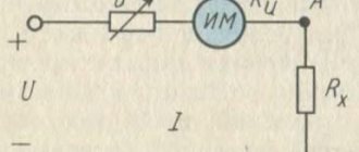
Other verification methods
You can check the capacitor without removing it from the microcircuit. To do this, you need to connect a known good capacitor with the same capacitance in parallel. If the device works, then the problem is in the first element and it should be changed. This method is applicable only in circuits with low voltage!
Sometimes the capacitor is checked for a spark. It needs to be charged and a metal tool with an insulated handle to close the terminals. A bright spark with a characteristic sound should appear. If the discharge is low, we can conclude that it is time to change the part. This measurement must be carried out wearing rubber gloves. This method is used to test powerful capacitors, including starting capacitors, which are designed for voltages of more than 200 Volts.
It is not advisable to use testing methods without special instruments
They are unsafe - with the slightest carelessness you can get an electric shock. The objectivity of the picture will also be impaired - exact values will not be obtained
KPI parameters
The main parameter for such parts, which will help determine the ability of the device to operate in an oscillatory circuit, has become the minimum and maximum capacitance. This indicator is most often indicated next to the variable capacitor itself on the device diagram.
It is worth noting that in devices such as radio receivers and radio transmitters, several oscillatory circuits are used at once. In order to configure the operation of several parts at once, capacitor blocks are used. One block most often consists of two, three or more KPI sections.
The rotor part for such units is usually mounted on one common shaft for all variable capacitors. This is done for convenience, since when just one rotor rotates, it becomes possible to change the capacity of all devices located in this section at once.
Types of supercapacitors
Where is artificial lighting used?
Ionistors are divided into three types:
- Ideal ionistor. The name was given to an ionic capacitor in which carbon electrodes were 100% polarized. In the complete absence of electrochemical processes, energy is accumulated due to the ion transfer of electrons from one electrode to another. The electrolyte in “ideal” ionistors are solutions of the base KOH and sulfuric acid H2SO4.
- Hybrid ionistors are capacitors with weakly polarizable electrodes. Energy accumulation in the DES occurs on the surface of one of the electrodes.
- Pseudoionistors have a high specific capacity. Reciprocal electrochemical reactions occur on the surface of the electrodes.
Supercapacitor device
PDA design
In order to change or determine the capacitance of a variable capacitor of this type, it is necessary to rotate the rotor. If we talk about the simplest equipment, then it most often uses a wire tuning capacitor. This part consists of a piece of copper wire with a diameter of 1-2 mm. The length of this element is 15-20 mm. An insulated wire with a diameter of 0.2-0.3 mm is wound onto the wire very tightly, turn to turn. In order to change the capacitance in this device, it is necessary to unwind the wire. To prevent the winding from slipping off at this time, it is necessary to impregnate it with any insulating compound.
How to make an ionistor with your own hands
Making an ionistor yourself is an ineffective waste of time, but for the sake of experiment you can try. It requires two metal plates (usually copper) that fit tightly to a layer of activated carbon on both sides. The coal layer is divided in equal parts by a thin dielectric plate. All coal is impregnated with electrolytes.
The result of amateur activity - a large ionistor with your own hands
Wires are soldered onto the plates in advance so that there is something to charge through. When power is applied, an electrical double layer will begin to appear on the pores of the activated carbon. The “filling” is prepared simply: the coal is pounded into dust and mixed with an electrolytic composition until the consistency of a thick porridge is obtained. Subsequently, it is spread on degreased and cleaned plates.
You might be interested in Energomera tse6803vm
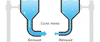
Resistance capacitance of a capacitor in an alternating current circuit
It is important to note here that current in a circuit in which there is a capacitor can only flow if the applied voltage changes. You also need to understand that the strength of the current that will circulate in the circuit during the discharge and charge of this element will be greater, the greater the capacitance of the capacitor itself, and will also depend on the speed at which changes in the electromotive force (EMF) occur.
One more property. A capacitor with variable capacitance, which is connected to a circuit with alternating current, will be a resistance for this circuit. In other words, the value of the capacitance resistance will be the smaller, the greater the value of the capacitance itself and the higher the frequency of the operating current. However, this statement is true only for a circuit in which the current is alternating. The capacitance of the capacitor is equal to infinity, that is, its resistance will be infinite if such an element is placed in a circuit with direct current.
How to test a battery with a load fork
Load forks of the type described above are suitable for checking the condition of 12-volt batteries (in this case, one load coil works) or high-capacity batteries (both coils work).
To check a car battery with a load fork, you must perform the following steps:
- First, the voltage is measured at the battery terminals without using load resistors. To do this, after the car has been turned off or the battery has stopped receiving current from charging, wait 6-7 hours.
- Take the device and connect its positive terminal with a similar battery terminal (without connecting the spiral).
- Using the negative pin on the body of the load plug, touch the negative terminal of the battery and see what the voltmeter shows.
- This checks the open circuit voltage of the battery. Next, the obtained data is compared with the value in the table and a conclusion is drawn about the state of charge of the battery. If everything is in order and the battery is charged one hundred percent, then you can proceed to measuring under load.
A voltmeter reading of 9.0 Volts is considered a good result - this means that the battery is in good condition. Other results indicate that the battery needs to be charged with a test measurement or replaced.