Before choosing a connection diagram for a single-phase asynchronous motor, it is important to determine whether to reverse. If for proper operation you will often need to change the direction of rotation of the rotor, then it is advisable to organize reversal using a push-button station. If one-way rotation is enough for you, then the simplest circuit without the possibility of switching will do. But what to do if, after connecting via it, you decide that the direction still needs to be changed? Single-phase 220V motor - how to change the direction of rotation?
Single-phase 220V motor - problem statement
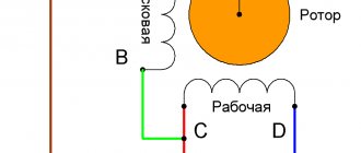
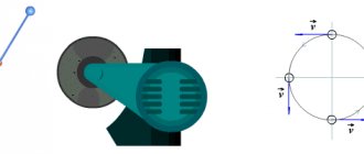
Let's assume that an asynchronous single-phase motor, already connected using a starting-charging capacity, initially has a shaft rotation directed clockwise, as in the picture below (single-phase motor 220V)
Let's clarify the important points:
- Point A marks the beginning of the starting winding, and point B marks its end. A brown wire is connected to the starting terminal A, and a green wire is connected to the ending terminal.
- Point C marks the beginning of the working winding, and point D marks its end. A red wire is connected to the initial contact, and a blue wire is connected to the final contact.
- The direction of rotation of the rotor is indicated by arrows.
We set ourselves the task of reversing a single-phase motor without opening its housing so that the rotor begins to rotate in the other direction (in this example, against the movement of the clock hand). It can be solved in three ways. Let's take a closer look at them.
Information
This site has been created for informational purposes only. The resource materials are for reference only.
When quoting site materials, an active hyperlink to l220.ru is required.
A document defining the rules of the device, regulating the principles of construction and requirements for both individual systems and their elements, units and communications of the power plant, conditions of placement and installation.
PTEEP
Requirements and responsibilities of consumers, responsibility for implementation, requirements for personnel operating the power plant, management, repair, modernization, commissioning of the power plant, personnel training.
POTEU
Rules for labor protection during the operation of electrical installations - a document created on the basis of the currently inactive Inter-industry rules for labor protection (POT R M-016-2001, RD 153-34.0-03.150).
Before choosing a connection diagram for a single-phase asynchronous motor, it is important to determine whether to reverse. If for proper operation you will often need to change the direction of rotation of the rotor, then it is advisable to organize reversal using a push-button station. If one-way rotation is enough for you, then the simplest circuit without the possibility of switching will do. But what should you do if, after connecting via it, you decide that the direction still needs to be changed?
Option 1: reconnection of the working winding (single-phase motor 220V)
To change the direction of rotation of the motor, you can only swap the beginning and end of the working (permanently on) winding, as shown in the figure. You might think that to do this you would have to open the case, take out the winding and turn it over. There is no need to do this, because it is enough to work with the contacts from the outside:
- There should be four wires coming out of the housing. 2 of them correspond to the beginnings of the working and starting windings, and 2 to their ends. Determine which pair belongs only to the working winding.
- You will see that two lines are connected to this pair: phase and zero. With the motor turned off, reverse the phase by changing the phase from the initial winding contact to the final one, and zero - from the final to the initial one. Or vice versa.
Connection diagram for a single-phase motor
As a result, we get a diagram where points C and D change places. Now the rotor of the asynchronous motor will rotate in the other direction.
What is the principle of reverse movement?
Since the operating principle of an alternating current electric motor is based on the rotation of magnetic fields in a certain direction, then to change it you will have to change the magnetic fields. The very principle of reverse operation is incredibly simple - you need to swap the wires responsible for the main rotation and launch. Since each of them is connected to both positive and negative, changing the wire completely inverts the polarity of the magnetic field. In turn, this means that it will begin to move in the opposite direction, dragging the rotor along with it, and with it the entire system in principle.
Option 2: reconnecting the starting winding (single-phase motor 220V)
The second way to organize the reverse of a 220 Volt asynchronous motor is to swap the beginning and end of the starting winding. This is done by analogy with the first option:
- Of the four wires coming out of the motor box, find out which of them correspond to the starter winding taps.
- Initially, end B of the starting winding was connected to the beginning C of the working winding, and beginning A was connected to the starting-charging capacitor. You can reverse a single-phase motor by connecting the capacitance to terminal B, and the beginning of C to the beginning of A.
After the actions described above, we get a diagram as in the figure above: points A and B have swapped places, which means the rotor began to turn in the opposite direction.
Commutator single-phase motors and their features
A single-phase motor is the most common motor in household conditions, which is often reproduced with one’s own hands. The reason for this lies in the single-phase 220V network supplied to most workshops, houses and private plots. However, before starting work, it is important to determine what type of motor you have in front of you - commutator or asynchronous. In most situations, there are markings on the mechanism, but if it came into your hands after repair or reconstruction, then it would be safer to pay attention to the presence of brushes in the mechanism, located near the commutator, as well as a copper drum, which is divided into equal sections.
Commutator motors are exclusively single-phase and are very common in household appliances. Among their advantages it is worth highlighting:
- quick start - immediately after the electricity is supplied, the motor begins to accelerate at a high number of revolutions;
- Convenience of reverse - thanks to the system, it is not difficult to reverse the rotor movement in the opposite direction. To do this, you need to change the polarity of the magnetic field;
- rotation speed adjustment - by changing the voltage amplitude and cutoff angle, you can control the intensity of the rotor.
For these reasons, commutator motors are used in household and construction equipment. However, they also have a number of disadvantages:
- high noise - when reaching high speeds, the engine begins to make a lot of noise. This smooths out at low rotations, but not as often;
- difficulty of maintenance - the commutator motor must be checked and cleaned regularly. Graphite from erasable brushes contaminates the current collector and disables the entire system.
We have already discussed the structure and principle of operation of asynchronous motors above. Unlike collector engines, such engines operate almost imperceptibly even at high speeds. Therefore, they are used in equipment that is critical to have low noise limits during long-term operation - for example, refrigerators, air conditioners and climate control systems.
Option 3: changing the starting winding to the working winding, and vice versa
It is possible to organize the reverse of a single-phase 220V motor using the methods described above only if taps from both windings with all beginnings and ends come out of the housing: A, B, C and D. But there are often motors in which the manufacturer intentionally left them outside only 3 contacts. In this way, he protected the device from various “homemade products”. But still there is a way out.
The figure above shows a diagram of such a “problematic” motor. It only has three wires coming out of the housing. They are marked with brown, blue and purple colors. The green and red lines corresponding to the end B of the starting winding and the beginning C of the working winding are interconnected internally. We will not be able to access them without disassembling the engine. Therefore, it is not possible to change the rotor rotation using one of the first two options.
In this case, do this:
- Remove the capacitor from the initial terminal A;
- Connect it to the final terminal D;
- From wires A and D, as well as the phase, taps are made (you can reverse it using a key).
Look at the picture above. Now, if you connect the phase to tap D, the rotor rotates in one direction. If the phase wire is transferred to branch A, then the direction of rotation can be changed in the opposite direction. Reversing can be done by manually disconnecting and connecting the wires. Using a key will help make the job easier.
It's important to understand
Important! The last version of the reversible connection diagram for an asynchronous single-phase motor is incorrect. It can only be used if the following conditions are met:
- The length of the starting and working windings is the same;
- Their cross-sectional area corresponds to each other;
- These wires are made from the same material.
Reversing circuits for a single-phase asynchronous motor without opening the housing
If you don’t want to interfere with the system of an automatic asynchronous motor, and for one reason or another there is no access under the housing, you can use one of three fairly simple reverse methods.
Reconnecting the working winding
We have already discussed a similar connection diagram above - it is used most often due to its simplicity. It does not require opening the housing or turning over the winding - it is enough to simply reconnect the terminals of the working wires so that the phase moves from the initial to the final contact, and zero - vice versa.
Reconnecting the starting winding
The system is the same as in the previous version, but with the difference that the wires will have to be changed at the starting winding. After reconnection, the rotor torque should also change.
Complete winding replacement
If you want to create a reliable connection, or the motor model is atypical (for example, with three wires instead of four), you should completely replace the winding. For this, a capacitor is used, which is connected to the final terminal, and reverse taps are launched from the wires. The advantage of this scheme is the fact that the reverse can be controlled if you connect the wires manually.
Variable network: motor 380 to network 380
To reversibly connect a three-phase asynchronous electric motor, we will take as a basis the circuit diagram for connecting it without reversing:
This scheme allows the shaft to rotate only in one direction - forward. To make it turn into another, you need to swap places of any two phases. But in electrics it is customary to change only A and B, despite the fact that changing A to C and B to C would lead to the same result. Schematically it will look like this:
To connect you will additionally need:
- Magnetic starter (or contactor) – KM2;
- Three-button station, consisting of two normally closed and one normally open contacts (a Start2 button has been added).
Important! In electrical engineering, a normally closed contact is a state of a push-button contact that has only two unbalanced states. The first position (normal) is working (closed), and the second is passive (open). The concept of a normally open contact is formulated in the same way. In the first position the button is passive, and in the second it is active. It is clear that such a button will be called “STOP”, while the other two are “FORWARD” and “BACK”.
The reverse connection scheme differs little from the simple one. Its main difference is the electric locking. It is necessary to prevent the motor from starting in two directions at once, which would lead to breakdown. Structurally, the interlock is a block with magnetic starter terminals that are connected in the control circuit.
To start the engine:
- Turn on the machines AB1 and AB2;
- Press the Start1 (SB1) button to rotate the shaft clockwise or Start2 (SB2) to rotate the shaft in the opposite direction;
- The engine is running.
If you need to change direction, you must first press the “STOP” button. Then turn on another start button. An electrical lock prevents it from being activated unless the motor is switched off.
Variable network: electric motor 220 to network 220
Reversing a 220V electric motor is only possible if the winding terminals are located outside the housing. The figure below shows a single-phase switching circuit, when the starting and working windings are located inside and have no outputs to the outside. If this is your option, you will not be able to change the direction of rotation of the shaft.
In any other case, to reverse a single-phase capacitor IM, it is necessary to change the direction of the working winding. For this you will need:
The circuit of a single-phase unit is almost no different from that presented for a three-phase asynchronous motor. Previously, we switched phases: A and B. Now, when changing direction, instead of a phase wire, a neutral wire will be connected on one side of the working winding, and on the other, a phase wire will be connected instead of a zero wire. And vice versa.
Variable network: 380V to 220V
To connect a three-phase asynchronous motor to a 220V power supply, it is necessary to use one or two capacitors to compensate for the missing phase: operating and starting. The direction of rotational movement depends on what the third winding is connected to.
To force the shaft to rotate in the other direction, winding No. 3 must be connected using a capacitor to a toggle switch with two positions. It should have two contacts connected to windings No. 1 and No. 2. Below is a detailed diagram.
Such a motor will play the role of a single-phase motor, since the connection was made using one phase wire. To start it, you need to move the reversing toggle switch to the desired position (“forward” or “backward”), then move the “start” toggle switch to the “on” position. At the moment of startup, you must press the button of the same name - “start”. You need to hold it for no more than three seconds. This will be enough for overclocking.
Constant electric current: features
DC motors are more difficult to connect than motors powered by AC power. Because in order to connect the windings, you need to know exactly what brand your unit is. Only then can you find a suitable scheme.
But in any DC electric motor there is an armature and an excitation winding. Based on the method of their inclusion, they are divided into units:
- with independent excitement,
- with self-excitation (divided into three more groups: serial, parallel and mixed connection).
Independently excited DC motors (shown schematically below) are used in production. Their winding has nothing to do with the armature, because it is connected to another electrical source.
Machine tools and fans use single-phase motors with parallel excitation. There is no need for a second source here.
Electric vehicles use units with sequential excitation.
If one winding is parallel to the armature and the other is serial, then this connection method is mixed. It is rare.
All methods of switching on DC motors can be reversed:
- If the excitation is sequential, then the direction of the current must be changed either in the exciting winding or in the armature;
- In any other case, it is recommended to change the winding only in the armature. If you change the winding, there is a danger that it will break. This will lead to a sharp increase in electromotive force, which will damage the insulation.
Reversing a separately excited DC motor is performed in the same way.
Keep in mind that the power supply is alternating current. But this does not mean that it is variable in all electrical appliances equipped with an electric motor and included in it. The current from the alternating phase can become constant by passing through the rectifier. There may be no phase power at all if the engine is powered from a battery.
Almost any electric motor can be made to rotate in one direction or the other. This is often necessary, especially when designing various mechanisms, for example, systems for closing and opening gates. Typically, the motor housing indicates the factory direction of the shaft movement, which is considered straight. Torsion in the other direction in this case will be reverse.
What is reverse
Simply put, reverse is a change in the direction of movement of any mechanism in the opposite direction from the selected main one. The reverse circuit can be obtained in several ways:
In the first case, by switching the gear connections connecting the drive shaft to the driven shaft, the latter is rotated in the opposite direction. All gearboxes work on this principle.
The electrical method involves a direct effect on the engine itself, where electromagnetic forces take part in changing the movement of the rotor. This method benefits from the fact that it does not require the use of complex mechanical transformations.
In order to obtain electric motor reverse, it is necessary to assemble a special electrical circuit, which is called a motor reverse circuit. It will differ for different types of electrical machines and supply voltage.
Reverse the engine using the NVD button
In a broad sense, reverse means a change in the movement of the rotor in the opposite direction relative to its normal start. Note that this is a fairly important function that is necessary in the vast majority of systems. Reversing can be done in any type of electric motor, both asynchronous, running on alternating current, and for a motor running on direct current.
Since asynchronous motors, including single-phase ones, are used in most fields of activity and even in household appliances, reverse is a necessary function for performing basic mechanical actions. A striking example is lifting mechanisms that need to move in all directions, various locking devices of the “open-close” format and similar executive structures. For them, the need to reverse the rotor is constant, since its movement in both directions is a basic function, without which they will not be able to perform their duties.
Temporary reverse is not used very often, and is usually needed in emergency situations. For example, asynchronous motors installed in conveyors, escalators and pumps operate strictly in one direction. However, if the mechanism breaks or jams, reverse is activated, allowing you to stop or reverse the operation of the system.
Reverse is also used for sharp and rapid braking of the electric motor. In normal cases, the rotor continues to rotate even after the mechanism is disconnected from the network, since the inertia gained during operation is very reluctant to be spent. Thus, the motor operates even after the mains is turned off, which in some cases is extremely undesirable. A short-term start of reverse creates a counter-directional force that absorbs inertia, as a result of which the rotor can be stopped much faster than it stopped rotating naturally. In a professional environment, such a brake is called back-on.
Where is reverse applied?
It is easier to list cases when reverse is not used. Almost all mechanics are based on transmitting torque clockwise and vice versa. This may include:
- Household appliances: washing machines, audio players.
- Power tools: reversible drills, screwdrivers, impact wrenches.
- Machine tools: boring, turning, milling.
- Vehicles.
- Special equipment: crane equipment, winches.
- Automation elements.
- Robotics.
The situation that an ordinary person most often encounters in practice is the need to assemble a circuit for connecting the reverse of an asynchronous AC electric motor or a DC commutator motor.
Connecting a 380 V asynchronous motor to a three-phase network in reverse
The connection diagram of an asynchronous machine in the forward direction has a certain sequence of supplying phases A, B, C to the motor contacts. It can be modified, for example, by adding a switch that would swap any two phases. In this way you can obtain a motor reverse circuit. In practical circuits, such phases are considered to be B and A.
- Magnetic type starters (KM1 and KM2).
- A station with three buttons, where two contacts have a normally open position (in the initial state the contact does not conduct current, when the button is pressed, the circuit closes), one is normally closed.
The scheme works as follows:
- By turning on the automatic fuses AB1 (power line), AB2 (control circuit), the current flows to the three-button switch and the terminals of the magnetic contactors, which are open in the initial state.
- By pressing the “Forward” button, the current passes to the coil of the electromagnet of contactor 1, which attracts the armature with power contacts. At the same time, the control circuit of contactor 2 breaks, and it is now impossible to turn it on with the “Reverse” button.
- The motor shaft begins to rotate in the main direction.
- By pressing the “Stop” button, the current in the control winding circuit is interrupted, the electromagnet releases the armature, the power contacts open, the blocking contact of the “Reverse” button closes, and it can now be pressed.
- When the “Reverse” button is pressed, similar processes occur only in the contactor 2 circuit. The motor shaft will rotate in the opposite direction from the main direction.
Connection diagram for an asynchronous motor with a starting winding: assembly sequence
For example, we have determined that there are four or three wires coming out of the stator. We call up the active resistance between them with an ohmmeter and determine the starting and operating windings.
Let’s assume that four wires have two pairs with resistances of 6 and 12 ohms connected to each other. Let's randomly twist one wire from each winding, designate this place as a “common wire” and get a measurement of 6, 12, 18 Ohms between the three terminals.
I marked the beginnings of the windings with dots on this diagram. For now, ignore this question. But, you will need to return to it further when the need arises to reverse.
The chain between the common terminal and the lower resistance 6Ω will be the main one, and the larger 12Ω will be the auxiliary, starting winding. Connecting them in series will show a total result of 18 ohms.
We mark these 3 ends with markings that are already clear to us:
Next we need a PNVS button, specially designed for starting single-phase asynchronous motors. Its electrical circuit is represented by three closing contacts.
But, it has an important difference from the start button of three-phase NVD electric motors: its middle contact is made with self-return, and not fixed when pressed.
This means that when the button is pressed, all three contacts are closed and held in that position. But, when you release your hand, the two outer contacts remain closed, and the middle one returns under the action of the spring to the open state.
We connect this button and the terminals for the output of the stator windings from the electric motor with a three-core cable so that the starting winding contact goes to the middle contact of the PNVS. We connect pins P and P to its outermost contacts and mark them.
On the back side of the button, between the contacts of the starting and working windings, we rigidly mount a jumper. We connect a 220 volt household power cable with a plug for installation in a socket to it and the second outer contact.
When this button is turned on, all three contacts will close, and the working and starting windings will begin to work. In just a couple of seconds the engine will finish accelerating and return to nominal mode.
Then the start button is released:
- the starting winding is switched off by self-return of the middle contact;
- the main winding of the motor continues to spin the rotor from a 220 V network.
This is the most affordable connection diagram for an asynchronous motor with a starting winding for the home craftsman. However, it requires the presence of a ventilator button.
If it is not there, and the electric motor urgently needs to be started, then it can be replaced with a combination of a two-pole circuit breaker and a conventional electric button of the appropriate power with self-reset.
You will have to turn them on at the same time, and release the button after spinning up the electric motor.
In order to consolidate the material on this topic, I recommend watching the video of the owner Oleg pl. It just shows the design of a built-in centrifugal regulator designed to automatically turn off the auxiliary winding.
Connecting a 220V motor to a single-phase network in reverse
In this case, it is possible to reverse the movement of the motor shaft if there is access to the terminals of its starting and operating windings. These motors have 4 outputs: two for the starting winding connected to the capacitor, two for the working one.
If there is no information about the purpose of the windings, it can be obtained by dialing. The resistance of the starting winding will always be greater than the working winding due to the smaller cross-section of the wire with which it is wound.
In a simplified version of the motor connection diagram, 220 V is supplied to the working winding, one end of the starting winding per phase or network zero (it makes no difference). The engine will begin to rotate in a certain direction. To get a reverse circuit, you need to disconnect the end of the starting winding from the contact and connect the other end of the same winding there.
To obtain a complete working circuit diagram, you need the following equipment:
- Safety circuit breaker.
- Push-button post.
- Electromagnetic contactors.
The reverse and forward circuit in this case is very similar to the connection circuit for a three-phase motor, but switching here occurs not of phases, but of the starting winding in one direction or the other.
Principle of operation
A single-phase asynchronous motor is a machine that has only one winding on the stator, which is powered by just one phase. In fact, even in the simplest design there are two windings, but the second acts as an auxiliary one and works exclusively when the engine is started, turning off during the process. Thus, the starting winding gives the rotor the necessary impulse, bringing the system out of balance - this is the simplest and most common way to push it.
The starting winding also differs from the working winding in size - it usually has half the number of slots. As in two-phase systems, both windings are located at right angles to each other. This allows you to generate the necessary force when starting work, then the starting phase is turned off, and then the engine maintains operation exclusively as a single-phase one.
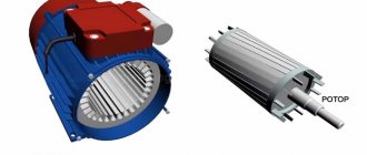
The design of the machine has a rotor and a stator, the first one must constantly rotate, and the second one must remain stationary. This is necessary to generate a magnetic field that will change over time. It is on the stator that the windings are located, while the rotor, through its rotation, ensures the operation of the entire mechanism. A single-phase motor has one of two types of rotors:
- short-circuited - also known as a “squirrel wheel”. It consists of a series of aluminum rods closed with rings at the ends;
- cylindrical - hollow inside, it is an empty cylinder.
Note that when the rotor rotates without using a starting winding, it enters a penetrating magnetic flux, which is generated by a pulsating field. If the system is at rest, then the rotor will not start in principle, since the total torque is zero, and both Ampere forces acting on the rotor completely compensate each other.
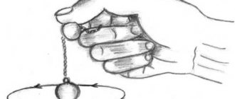
The situation changes if the rotor is pushed - it begins to move in the direction of the starting push. The law of electromagnetic induction begins to work, as a result of which the system generates corresponding currents in the direction of the push. However, the question arises: what determines its direction?
To do this, two factors need to be taken into account:
- placement of the starting winding relative to the rotor;
- phase shift of the current relative to the working winding.
If both factors satisfy the system parameters, then their combined action will be sufficient to generate a pulsating and rotating magnetic field. This sets the engine in motion, after which the starting phase is turned off, and then it operates on only one - it is enough to maintain the given rotation speed.
The bias in most cases is carried out using a special capacitor built into the system. Connected with the starting winding in a series circuit, it creates a phase shift of 90 degrees. From a technical point of view, the operator of the machine must press the button of the switch that supplies power to the circuit and release it only at the moment when the revolutions become equal to the corresponding rating indicated in the given frequency of the circuit.
Thus, for capacitor starting, reverse is carried out by creating a condition under which the push that starts the rotor is produced in the opposite direction than under normal conditions. This can be achieved if you correctly alternate the phases in both windings, which requires fine tuning. To do this, you need to switch the starting and working windings to change the overall polarity of the connection. You can perform a similar procedure manually by simply changing the terminals brought out. To understand which of them belongs to which winding, use a multimeter - a lower active resistance, which will help you find the working one.
Reversing diagram of a three-phase motor in a single-phase network
Since a three-phase asynchronous motor will lack two phases, they need to be compensated with capacitors - starting and running, to which both windings are switched. The torsion of the shaft in one direction or another depends on where to attach the third.
The diagram below shows that winding number 3 is connected through a working capacitor to a three-position toggle switch, which is responsible for the forward/reverse engine operating modes. Its other two contacts are combined with windings 2 and 1.
When turning on the engine, you must adhere to the following algorithm of actions:
- Apply power to the circuit through a plug or switch.
- Move the toggle switch to switch operating modes to forward or reverse (reverse).
- Set the power switch to the ON position.
- Press the “Start” button for a time not exceeding three seconds to start the engine.
Reverse capacitor motor
Due to the peculiarities of the mechanism, the capacitor engine only activates reverse if there are capacitors present. If you exclude them from the system, the motor will turn on, but the start will not occur, since sufficient force is not generated to start.
The first circuit includes a capacitor installed in the starting winding power circuit. Having an excellent start, such a mechanism greatly sags in power, which turns out to be below the nominal. The second connection scheme operates in the opposite way - by connecting a capacitor to the working winding circuit, you get a relatively difficult start, but the performance characteristics remain at a high level. Thus, both circuits find their application in different conditions - the first is needed for devices with heavy starting, and the second in devices that vitally require performance.
The third option involves installing two capacitors at once. This option is most often chosen, since it takes the best of both schemes - an excellent start and decent performance, but in return it requires more careful setup, regular maintenance and a special PVS button. During operation, both windings, both starting and working, remain active, and the first, even when turned off, continues to operate through the capacitor.
The key point in implementing reverse using capacitors is their correct choice. To correctly calculate their characteristics, experts use a complex formula with several variables. However, in practice everything turns out to be simpler if you follow a couple of recommendations:
- for the working capacitor, you should choose characteristics in the region of 70-80 μF per 1 kW of total engine power;
- for a starting capacitor, such indicators should be 2 or even 3 times higher;
- The capacitor voltage must exceed the mains voltage by at least one and a half times. For example, for a standard single-phase network of 220 V, you should select a capacity of 330, 380 V or more.
Note that there are specialized capacitors on the electronics market that were originally designed for starting. They are marked accordingly and provide a smooth start.
Connection diagram for a motor with DC reverse
DC motors are somewhat more difficult to connect than AC electric machines. The difficulty is that the designs of such devices can be different, or rather the method of exciting the winding is different. On this basis, engines are distinguished:
- Independent method of excitation.
- Independent excitation (there are serial, parallel and mixed connections).
Regarding the first type of devices, here the armature is not connected to the stator winding; they are each powered from its own source. This achieves the enormous power of the engines used in production.
In machine tools and fans, parallel excitation motors are used, where the source energy is the same for all windings. Electric vehicles are built on the basis of series excitation of windings. Mixed excitement is less common.
In all types of engine designs described, it is possible to start the rotor in the opposite direction from the main stroke, that is, in reverse:
- With a sequential excitation circuit, it does not matter where to change the direction of the current in the armature or stator - in both cases the motor will operate stably.
- In other options for excitation of machines, it is recommended to use only the armature winding for reversing purposes. This is due to the danger of a break in the stator, a jump in the electromotive force (EMF) and, as a result, damage to the insulation.
Wiring diagram for an asynchronous motor with capacitor start: 3 technologies
The stator with windings for starting from capacitors has approximately the same design as discussed above. It is difficult to distinguish it by appearance and simple measurements with a multimeter, although the windings may have equal resistance.
Refer to the nameplate and table from Aliyev’s book. You can try to connect such an electric motor using a circuit with a PNVS button, but it will not spin up.
It will not have enough starting torque from the auxiliary winding. It will hum and twitch, but will not reach the rotation mode. Here you need to assemble a different capacitor starting circuit.
The 2 ends of different windings are connected to a common terminal O. A household voltage of 220 volts is supplied to it and the second end of the working winding through an AB switching device.
The capacitor is connected to the terminals of the starting and operating windings.
As a switching device, you can use a double circuit breaker, a switch, NVD or NVDS type buttons.
Here it turns out that:
- the main winding operates directly from 220 V;
- auxiliary - only through the capacitor.
This circuit is used for easy starting of capacitor electric motors that are put into operation without heavy load on the drive, for example, fans, sanders.
If, at the moment of starting, it is necessary to simultaneously spin the belt drive, gear mechanism of the gearbox or other heavy drive, then a starting capacitor is added to the circuit, which increases the starting torque.
It is convenient to describe the operating principle of such a scheme using the same PVS button.
Its self-resetting contact is connected to the auxiliary winding through an additional starting capacitor Sp. The second end of its plate is connected to terminal P and working capacity Cp.
An additional capacitor at the moment of starting an electric motor with a heavy drive helps it quickly reach its rated rotation speed, and then simply turns off so as not to create overheating of the stator.
This circuit is fraught with one danger associated with long-term storage of a capacitive charge by the starting capacitor after removing power 220 when the electric motor is turned off.
If the worker is not careful or careless, the discharge current can pass through the human body. Therefore, the charged capacity must be discharged.
In the scheme under consideration, after removing the voltage and pulling out the plug and power cord from the socket, this can be done by briefly turning on the PVS button. Then the capacitance Sp will begin to discharge through the starting winding of the motor.
However, not all people do this for various reasons. Therefore, it is recommended to install two additional resistors in the starting circuit.
Resistance Rр is selected with a nominal value of about 300÷500 Ohms of several watts. Its task is to discharge the auxiliary capacitance Sp after removing the supply voltage.
The Ro resistor is low-resistance and powerful and acts as a current-limiting resistance.
Where can I get the values of the main and auxiliary capacitors?
The fact is that the factory determines the value of the starting and operating capacitance for capacitor starting of a single-phase IM individually for each model and indicates this value in the passport.
There are simply no separate formulas for calculating how it is done for capacitor starting of a three-phase motor in a single-phase network using star or delta circuits.
You will need to look for factory recommendations or experiment during the setup process with different containers, choosing the most optimal option.
The owner of the video “IV I'm Interested” shows how to optimally configure the parameters of a capacitor motor starting circuit.
Starting the motor with a star-delta circuit
When directly starting powerful three-phase electric motors using a reverse control circuit, voltage drops occur in the network. This is due to the large inrush currents flowing at this moment. To reduce the current value, use a gradual start of the motor according to the star-delta circuit.
The bottom line is that the beginning and end of each stator winding are led out into a terminal box. The circuit is controlled by three contactors. They gradually turn on the windings in a star, and then, when the engine accelerates, they bring the system to operating condition when connected in a delta.
How to distinguish a reversing starter from a direct one
A reversing starter is a more complex device. In fact, it consists of two conventional direct starters, the latter combined in one housing. The internal circuitry of the reversing device is characterized by the fact that it is impossible to run two modes at the same time - direct and reverse. This process is controlled by a blocking circuit, which can be electrical or mechanical.