| Parameter | Meaning |
| Operating measured voltage, V | ~50-400, 50 (+/-1) Hz |
| In active load, A | 50 |
| Imax active load, A | 60 |
| Rated power Pnom, W | 10000 |
| Maximum power Pnom, W | 12500 |
| Adjustable lower value Ulow shutdown, V | 120-200 (170) |
| Adjustable upper value Uup shutdown, V | 210-270 (250) |
| Shutdown time according to Umax (upper limit), no more, sec | 0,04 |
| Shutdown time according to Umin (lower limit), no more, sec | 0.06 (<120 V) / 1 (120-200 V) |
| Shutdown time, sec when In is exceeded | 600 |
| Shutdown time, sec when Imax is exceeded | 0,04 |
| Adjustable turn-on delay time (voltage protection), sec | 5-600 |
| Default turn-on delay time (factory setting), sec | 15 |
| Switching on after current protection has tripped | forcibly |
| Current protection shutdown function | There is |
| Calibration of instrument readings | There is |
| Voltage measurement error, % no more | 1 |
| Current measurement error, % no more | 1 |
| Case size, 17.5 mm modules | 3 |
| Operating temperature, C° | -25…+50 |
| Device protection degree | IP20 |
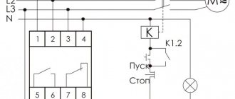
Voltage relay connection diagram
Let me show you once again what the connection of a voltage relay in an electrical panel looks like:
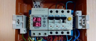
Voltage relay installed in the electrical panel. Voltage 220V.
The photo shows a Digitop voltage relay, as a review I can say that I connected these several times, there were no problems.
The voltage relay must be protected by an input circuit breaker. The machine can be placed before or after the counter, but it must be there in any case. The rating of the machine is one step less than the rated current of the voltage relay. In the above case, this rule does not apply:
Automatic machines, counter, voltage relay
In justification, I can say that in voltage relays they usually put a relay one step larger. I discovered the Ukrainian Barrier and Digitop, for example, with a nominal value of 32 A, the voltage relay circuit contains a 40 A relay, which is very commendable.
general description
Voltage relay with current control VA-50 is one of the powerful devices in the new line of VA-protector TM DigiTOP devices. It is recommended for installation if there is an electric stove and electric oven in the house, which consume significant power over a long period of time. Rated long-term load no more than 10 kW, maximum 12.5 kW. The VA-50 DigiTOP 50 ampere voltage relay with current control provides overvoltage protection for household and industrial appliances and built-in electronic overcurrent and short circuit protection.
Voltage relay connection
How to connect the voltage relay is shown in the diagram below:
Voltage relay connection diagram
This is a standard scheme. Thick lines show power circuits.
If you are on the safe side, it is better to use an automatic bypass in the connection diagram (not shown in the diagram, but is in the photo above), as is done in voltage stabilizers. This is done so that the consumer can at least work if the voltage goes beyond the limits. If necessary.
The bypass machine is connected parallel to the internal relay contacts of our voltage relay. If we take the connection diagram given above, then this is between pins 2 and 3.
A bypass can also be useful if the voltage relay itself fails.
Purpose
Voltage relay with current control VA-50 TM DigiTOP, designed for a rated transit load of up to 50 amperes over a long period of time.
This model is the optimal choice if the urgent question is that the safety margin of protection at 40A may not be enough now or in the future, and the input machine exceeds this rating. Using the VA-50 model will allow you to safely use the full potential of the permitted power of your input and eliminate the normal operation of the protection at a load exceeding 40 amperes. This is relevant for fairly powerful single loads, such as an electric stove, electric oven, especially in combination with a water heating tank. If you want to buy a voltage relay with current control, you should also not forget about other powerful loads, such as a washing machine and iron. Individually, these devices do not have large critical consumption, but are often used in combination. The maximum permitted current for the VA-50 is 60 amperes, which allows you to obtain the necessary operational reserve and not worry about uninterrupted and high-quality protection of your household appliances and equipment. The main function of this device is to monitor the parameters of the power supply network and protect your electrical equipment from damage as a result of high or low voltage, as well as the distribution network from overload and short circuit. To do this, this device uses two different directions of electronic control with one powerful power disconnector, which turns off your network in the event of an emergency in the external network or an overload or short circuit in the internal one.
Voltage relay for powerful consumers
If the consumer current is more than 63A, and frequent operations are expected, then it is better and more reliable to use an additional starter. I have already written about choosing a starter (or contactor).
By the way, if you are at all interested in what I write about, subscribe to receive new articles and join the group on VK!
In this case, the contacts of the voltage relay (16 or 20A) turn on the starter coil, and the starter with its contacts can already turn on a load of tens of kilowatts, if necessary.
Review of voltage relay with current control DigiTop VA-protector 63A
Intro
When renovating your future home, in addition to re-wiring all the wiring in the apartment and installing a panel with automatic circuit breakers, the question arose about ensuring the protection of equipment from overvoltage. The constant construction of new houses requires the laying of new and new power cables with voltages of 35 and 110 kV, but they “forget” to compensate for their capacity: shunt reactors are simply not installed. This is what causes resonance with power pumping. In particular, a similar thing happened on December 2 in Kyiv, when the generator at TPP-5 “fell off” and in some areas of Kyiv a decent amount of equipment burned out due to a power surge. Hidden text
This prompted me to select and install a voltage relay (RN). When searching for existing solutions, devices from well-known European brands or did not provide the required characteristics (since LVs are used mainly in industry, they are designed for a current of up to 10 A and are installed in tandem with a contactor, which requires a minimum of 4 seats per DIN rail, which I didn’t have), or cost a decent amount.
A quick analysis of devices from domestic manufacturers showed that the devices are of low quality and, at times, even dangerous for use, as evidenced by reviews and tests of similar devices on various forums:
krainamaystriv.com/threads/12117 krainamaystriv.com/threads/10395 krainamaystriv.com/threads/9559 krainamaystriv.com/threads/3885
There were also mentions of the new DigiTop relays and statements that they were much better than what was produced previously. Unfortunately, it was not possible to find a review or at least a photo of the insides of the device. It was decided to buy a pig in a poke and disassemble it, because... I didn’t want to trust an unknown box with the safety of the whole house.
Specifications
| Parameter | Meaning |
| Device input voltage: | 0-400V |
| Displayed voltage: | 50-400V |
| Voltmeter error: | no more than 5 V |
| Maximum load current: | no more than 80A |
| Upper limit shutdown time: | 0.02 sec |
| Low limit shutdown time | no more than 1 sec (120-200V) 0.02 sec (<120V) |
| Current trip time | 600 sec (Inom< Imeas< Imax:); 0.04 sec (Imeas≥Imax) |
| Lower trip limit (step 1B): | 120-200 V |
| Upper trip limit (step 1B): | 210-270 V |
| Turn-on delay time (5 sec step): | 5-600 sec |
Design
The device is produced in a three-unit housing (according to DIN 43 880, for a mounting strip in accordance with EN 50 022, the width of one module mounted on the strip is set to 17.5 mm) for installation on the mounting profile TH/35-7.5 and TH/35-15 - in popularly - DIN rail.
The manufacturer declares the case material as ABS plastic, which does not support combustion. The drawback is the tongue that secures the device body to the DIN rail: it is frankly rather weak and the device can move freely from side to side. On the front panel there are 2 LED digital indicators (three-digit seven-segment with a dot), covered with red matte plastic, they are quite bright. To the right of them are 3 control buttons.
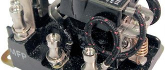
The conductors are connected from below. The terminals are made of copper and brass. They are quite massive.
The connection of the switching relay to the terminals is carried out using a flexible copper bus, resistance welded at both ends (Jack 3.5 mm - for comparison).
Circuit design
The power part of the device is built on the basis of the Chinese relay NRL08B-12D (www.terraelectronica.ru/pdf/NCR/NRL-08B.pdf).
This is a latching relay with normally open contacts. The Datasheet tells us that it is capable of breaking a load of 15000VA, which is 68A at 220V. The contacts are made of silver plated. The maximum response time is 15ms.
The power supply for the control part is made on the basis of a specialized IC LNK304-306 for power supply without galvanic isolation.
Schema from datasheet
A good solution, in my opinion, in contrast to what was previously used on ballast capacitors.
At the input of the power supply, a limiter is installed on a field-effect transistor, which limits the voltage on the electrolytic capacitors and the input of the microcircuit (LNK304-306).
The control part is made on a PIC controller.
Allows you to set the upper and lower voltage limits, set the delay for turning on the device after the protection is triggered, enable or disable current protection. The device does not allow you to set the shutdown time at Inom< Imeas< Imax. The choice of shutdown current is possible only when selecting the device rating (32, 40, 50 and 63 A).
Ergonomics
Operating the device is simple and intuitive. Certain inconveniences are caused by the speed of increase/decrease of voltage thresholds and delays in the settings mode - 1V/sec and 5s/sec both when held and pressed frequently.
Installation quality
The installation was done well, the soldering is shiny, there is moderate amount of solder. Flux residues have been removed almost everywhere. There are slight discrepancies between the dimensions of the parts and their seats.
conclusions
The relay in question is a high-quality All-in-one product at an affordable price. The manufacturer has thoroughly redesigned the design, used a competent circuit design and good components. There are some shortcomings that do not affect the performance of the device. My rating is 4+. It is not scary to install such a device to protect the entire house.
Result
In crowded but not mad
PS:
Please send all comments regarding errors, typos and inaccuracies to a PM.
Shipping and payment
To buy a voltage relay with current control VA-50 for 50 A, or any other protection rating you are interested in, you can simply add the product you like to the cart and place an order. When placing an order through the shopping cart, you must indicate your name and phone number. Also, in the order form you can specify your email, delivery address, payment method and notes on the order (for example, time or day of delivery).
The more contact information you provide, the easier and faster we will contact you. In addition, you can place an order by calling us at the numbers listed in the contacts section (89615060305) or sending an email to our mail
Warranty: 24 months.
Why do you need a voltage control relay?
Household electrical appliances are designed for a voltage of 220-240 V. From time to time, emergency situations arise in the electrical network. The voltage in the outlet jumps up or down. Jumps can disrupt the operation of household appliances or completely destroy them.
Voltage drops in the network
A common case of voltage drops is a zero break. In this case, in one phase the voltage drops below the permissible level. On the other, on the contrary, there is a significant increase in voltage up to 380V.
Another situation is typical for old houses with poor electrical wiring and loose contacts. Due to the poor condition of the cables and their overload, the voltage in the sockets can drop to 170 V or lower. This is dangerous for electric motors of washing machines and refrigerators.
A voltage control relay protects electrical appliances. This small device is located in the distribution panel of the apartment. It has a compact design, is conveniently mounted on a DIN rail and performs its task completely autonomously.
Additional Information. It is necessary to distinguish voltage control relays from all kinds of stabilizers and UZMs. All of the listed devices are used to protect household appliances. The stabilizer is an active device. He is able to independently adjust the voltage in the apartment. The RN performs a simpler and more passive function. It simply turns off the consumer when the permissible threshold is exceeded and, in itself, does not affect the voltage in any way.
Step-by-step installation instructions
The voltage control relay can be installed in two ways.
The first involves finding and hiring a trusted electrician who will install it without problems and in a short time. The second way is to install the voltage relay yourself. Self-installation will not require much effort, since the process of connecting it cannot be called a difficult task.
Installation of the device must be carried out with the voltage turned off, therefore, before starting work, you must turn off the circuit breaker.
Next, you need to install the device on a DIN rail. When purchasing a device, a passport must be issued for it, which indicates the numbers of the input and output terminals. If the device is installed in a single-phase network, then the connection is made according to the first connection diagram, which is indicated above. If it is necessary to install on three phases, then the second or third switching circuit is selected.
The conductors that are connected to the device must be unburnt and properly cleaned of insulation. If the wire is stranded, then you need to install a special tip on it or tin it with a soldering iron. The bolts on the device must be firmly tightened. Since poor contact may cause the device to fail.
Tip #2: After connecting the device, it must be checked for functionality. For this purpose, the response thresholds are set to minimum - since the network has alternating voltage, the device can often be turned off (monitoring is carried out using a tester).
Setting LV response thresholds
The overvoltage protection relay is configured after analyzing the current state of the electrical network and wiring . It is necessary to pay attention to factors such as:
- Voltage at the socket. It is 220 V only on the pages of textbooks. The actual voltage in the network can be in the range of 190-240 V. It makes no sense to configure the LV to turn off when it drops to 210 V, if the voltage in the outlet rarely rises above 200 V. This is especially true for rural areas and in a private house.
- Power of household appliances. Some types of equipment consume high currents at the moment of startup, which sharply reduces the voltage in the network. This dip must be taken into account in order to select the lower protection threshold.
- At night the opposite happens. People are sleeping. Most of the electrical appliances in the house are turned off. The voltage in the network can go off scale up to 230-240 V. This phenomenon is taken into account when choosing the upper response rating.
Installation and configuration of voltage relays