Best answers
A:
Apply power to pins 11 and 4, connect headphones to pins 9 and 13 via 10uF, for example, and touch the 5,6 and 3,2 pins - if the ms is working, the background in the headphones will be 50Hz. So I tested this MS about 20 years ago - the easiest way, probably.
El Kunkin:
replacement only—————solder the socket and plug in the mikrukha————well, or if you have an oscillation generator, then it’s easier
Georgy Glurjidze:
Only by connection
Techie:
only by connection
Andrey Nechaev:
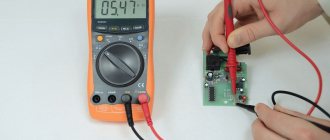
You can throw off the tester to check the op-amp. You can assemble a headphone amplifier on a breadboard. R1 R2 amplifier gain.
Details
All circuits are powered by a 4.5V “flat” battery. When connecting the power, you must strictly observe the polarity, because by mixing up the “plus” and “minus” you can completely damage the microcircuit.
Remember, the “plus” is supplied to its 14th pin, and the minus to the 7th. And only this way, and not otherwise. A wide variety of parts can be used in circuits.
Electrolytic capacitors (polar) can be of the K50-35 type or imported analogues of the K56-35. Resistances and capacitances do not have to be exactly the same as in the diagram; their values may differ from those indicated by 20-30%.
RK-11-19.
Three options
Checking microcircuits is a rather complex process, which often turns out to be impossible. The reason lies in the fact that the microcircuit contains a large number of different radioelements. However, even in this situation there are several ways to check:
- visual inspection. By carefully examining each element of the microcircuit, you can detect a defect (cracks in the case, burnt contacts, etc.);
- checking power with a multimeter. Sometimes the problem lies in a short circuit on the part of the power supply; replacing it can help correct the situation;
- performance check. Most microcircuits have not one, but several outputs, so a malfunction of at least one of the elements leads to failure of the entire microcircuit.
The easiest to check are the KR142 series microcircuits. They have only three pins, so when any voltage level is applied to the input, a multimeter checks its level at the output and draws a conclusion about the state of the microcircuit.
The next most difficult tests are the K155, K176, etc. series microcircuits. To check, you need to use a block and a power source with a specific voltage level selected for the microcircuit. Just as in the case of KR142 series microcircuits, we apply a signal to the input and monitor its output level using a multimeter.
Radio circuits. – Equalizer on the K157UD2 chip
materials in category
An equalizer is a device designed to adjust the frequency response of sound-reproducing equipment.
The equalizer consists of several controls with which you can change the transmission coefficient of the amplification device in fairly narrow frequency bands.
This allows you to obtain a complex frequency response shape that cannot be realized with traditional tone controls.
As a result, the listener has the opportunity to significantly change the nature of the reproduced sound picture and thus compensate for frequency distortions introduced by sound program sources, speaker systems and listening rooms.
Equalizers are usually built on the basis of active bandpass filters on an op-amp , and the more filters, the more the frequency response can be changed. However, a significant increase in their number greatly complicates equalizer control, so the number of filters is usually limited to 8-10.
Below is a description of an eight-band equalizer using the K157UD2 microcircuit . Its operating frequency range is 20…20,000 Hz;
Using a special tester
For more complex checks, you need to use a special microcircuit tester, which you can purchase or make yourself. When dialing individual components of the microcircuit, data will be displayed on the display screen, analyzing which you can come to a conclusion about the serviceability or malfunction of the element.
It is worth remembering that in order to fully test the microcircuit, you need to completely simulate its normal operating mode, that is, ensure the supply of voltage at the required level. To do this, the test should be carried out on a special test board.
Often, it turns out to be impossible to test a microcircuit without soldering the elements, and each of them must be called separately. How to ring individual elements of the microcircuit after desoldering will be discussed below.
Verification methods
Chip testing is a difficult, sometimes impossible process. It's all about the complexity of the microcircuit, which consists of a huge number of different elements.
There are three main ways to check a microcircuit without desoldering, with or without a multimeter:
- External inspection of the microcircuit. If you look at it carefully and examine each element, it is possible that you will be able to find some visible defect. This could be, for example, a burnt-out contact (perhaps more than one). Also, when conducting an external inspection of the microcircuit, you can detect a crack in the housing. With this method of checking the microcircuit, there is no need to use a special multimeter device. If defects are visible to the naked eye, you can do without devices.
- Checking the microcircuit using a multimeter. If the cause of the part failure is a short circuit, you can solve the problem by replacing the battery.
- Detection of violations in the operation of outputs. If a microcircuit has not one, but several outputs at once, and if at least one of them works incorrectly or does not work at all, then this will affect the performance of the entire microcircuit.
Of course, the easiest way to check a microcircuit is the first of those described above: that is, inspecting the part. To do this, just look carefully first at one side of it, and then at the other, and try to notice any defects. The most difficult way is to check with a multimeter.
The influence of the variety of microcircuits
The complexity of verification largely depends not only on the method, but also on the schemes themselves. After all, these parts of electronic computing devices, although they have the same construction principle, are often very different from each other.
For example:
- The easiest to check are the circuits belonging to the KR142 series. They have only 3 pins, therefore, as soon as any voltage is applied to one of the inputs, a tester can be used at the output. Immediately after this, you can draw conclusions about performance.
- More complex types are “K155″, “K176″. To check them, you have to use a block, as well as a current source with a certain voltage value, which is specially selected for the microcircuit. The essence of the check is the same as in the first option. You just need to apply voltage to the input, and then use a multimeter to check the output values.
- If it is necessary to carry out a more complex test - one for which a simple multimeter is no longer suitable, special testers for circuits come to the aid of radio electronics engineers. The method is called ringing the microcircuit with a multimeter tester. Such devices can either be made independently or purchased ready-made. Testers help determine whether a particular circuit node is working. The data obtained during the test is usually displayed on the device screen.
Main settings
If you look closely at the electrical characteristics of the K157UD2, you will notice that in terms of performance, this microcircuit is not for use in audio devices. Thus, the highest rate of voltage rise at its output is 0.5 V/µs, which is comparable to an output signal of up to approximately 10 V/8 kHz. In real life it will be even lower. But for its time it was also a good indicator.
Maximum values
Here are the main limit values of the parameters:
- maximum power supply (UPit) up to ±18 V;
- output voltage (Uout max.) up to ± 13 V (at Upit = ± 15 V);
- zero offset voltage (U cm) up to ± 13 V;
- current consumption (I sweat) up to 7 mA;
- short circuit current (I short circuit) up to 45 mA;
- cutoff frequency (f srz) from 1 MHz;
- gain (KуU): no less than 50000 (at f =0...50 Hz) and 800 (at f =20 kHz);
- output slew rate (VUout) of at least 0.5 V/µs.
Exceeding the maximum permissible values may lead to device failure.
The typical value of the noise voltage used at the input of this op-amp (in the frequency range from 20 to 20,000 Hz) is no more than 1.6 μV.
Analogs
It is believed that the imported analogue of the K157UD2 is LM301. But, firstly, this microcircuit has 8 pins, instead of 14. Therefore, to replace it you will have to look for two such devices. Secondly, they will be very difficult to find in our stores.
What else can replace K157UD2? A good alternative for this device is the new LME49XXX series microcircuits. More precisely, in most cases the following are suitable: LME49720, LME49860 and LM4562. They are very similar in their characteristics to the one under consideration, they have good linearity and bandwidth (up to 90 Hz), not only at a gain of 1, but also significantly higher (1000 and higher).
Typical noise voltage in the frequency range from 20 to 20,000 Hz is within 0.4 μV. Domestic analogues: KR1434UD1A and updated modification K157U D3. The problem is that now they are difficult to find on Russian shelves and they are more expensive.
Sound alarm circuit
Figure 5 shows a diagram of a sound alarm that emits intermittent sound signals. Moreover, the sound tone and interruption frequency can be adjusted. It can be used, for example, as a small siren or apartment bell.
Rice. 5. Diagram of a sound signaling device that emits intermittent sound signals.
A multivibrator is made on elements D1.3 and D1.4, generating audio frequency pulses, which are supplied to speaker B1 through an amplifier on transistor VT5.
The tone of the sound depends on the frequency of these pulses, and their frequency can be adjusted by variable resistor R4. To interrupt the sound, a second multivibrator is used on elements D1.1 and D1 2. It produces pulses of a significantly lower frequency.
These pulses arrive at pin 12 of D1.3. When the logical zero here, the multivibrator D1.3-D1.4 is turned off, the speaker is silent, and when it is one, a sound is heard.
Thus, an intermittent sound is obtained, the tone of which can be adjusted by resistor R4, and the interruption frequency by R2. The sound volume largely depends on the speaker.
And the speaker can be almost anything (for example, a speaker from a radio, a telephone, a radio point, or even a speaker system from a music center).
Transistors (field-effect and bipolar)
We switch the multimeter to the “testing” mode, connect the red probe to the base of the transistor, and touch the collector terminal with the black one. The display should show the breakdown voltage value.
A similar level will be shown when checking the circuit between the base and emitter. To do this, connect the red probe to the base, and apply the black probe to the emitter.
The next step is to check the same transistor terminals in reverse connection. We connect the black probe to the base, and with the red probe we touch the emitter and collector in turn. If the display shows one (infinite resistance), then the transistor is working. This is how field-effect transistors are tested.
Bipolar transistors are checked using a similar method, only the red and black probes are swapped. Accordingly, the values on the multimeter will also show the opposite.
Verification methods
Chip testing is a difficult, sometimes impossible process. It's all about the complexity of the microcircuit, which consists of a huge number of different elements.
There are three main ways to check a microcircuit without desoldering, with or without a multimeter:
- External inspection of the microcircuit. If you look at it carefully and examine each element, it is possible that you will be able to find some visible defect. This could be, for example, a burnt-out contact (perhaps more than one). Also, when conducting an external inspection of the microcircuit, you can detect a crack in the housing. With this method of checking the microcircuit, there is no need to use a special multimeter device. If defects are visible to the naked eye, you can do without devices.
- Checking the microcircuit using a multimeter. If the cause of the part failure is a short circuit, you can solve the problem by replacing the battery.
- Detection of violations in the operation of outputs. If a microcircuit has not one, but several outputs at once, and if at least one of them works incorrectly or does not work at all, then this will affect the performance of the entire microcircuit.
Of course, the easiest way to check a microcircuit is the first of those described above: that is, inspecting the part. To do this, just look carefully first at one side of it, and then at the other, and try to notice any defects. The most difficult way is to check with a multimeter.
The influence of the variety of microcircuits
The complexity of verification largely depends not only on the method, but also on the schemes themselves. After all, these parts of electronic computing devices, although they have the same construction principle, are often very different from each other.
For example:
- The easiest to check are the circuits belonging to the KR142 series. They have only 3 pins, therefore, as soon as any voltage is applied to one of the inputs, a tester can be used at the output. Immediately after this, you can draw conclusions about performance.
- More complex types are “K155″, “K176″. To check them, you have to use a block, as well as a current source with a certain voltage value, which is specially selected for the microcircuit. The essence of the check is the same as in the first option. You just need to apply voltage to the input, and then use a multimeter to check the output values.
- If it is necessary to carry out a more complex test - one for which a simple multimeter is no longer suitable, special testers for circuits come to the aid of radio electronics engineers. The method is called ringing the microcircuit with a multimeter tester. Such devices can either be made independently or purchased ready-made. Testers help determine whether a particular circuit node is working. The data obtained during the test is usually displayed on the device screen.
It is important to remember that the voltage supplied to the chip (microcontroller) should not exceed the norm or, conversely, be less than the required level. Preliminary testing can be carried out on a specially prepared test board.
Often, after testing a microcircuit, it is necessary to remove some of its radioelements. In this case, each of the nodes must be checked separately.
Transistor performance
Before checking a radio component with a multimeter, without desoldering, it is necessary to determine which of the two types the transistor belongs to - field-effect or bipolar. If the first, then you can use the following verification method:
- Set the device to the “diagnosis” mode, and then use the red probe, connecting it to the element being tested. The other - black - probe should be attached to the collector terminal.
- Immediately after completing these simple steps, a number will appear on the device screen that will indicate the breakdown voltage. A similar level can be seen when performing a “ringing” of the electrical circuit between the emitter and the base. It is important not to confuse the probes: the red one should be in contact with the base, and the black one with the emitter.
- Next, you can check all the same transistor outputs, but in reverse connection: you will need to swap the red and black probes. If the transistor works well, then the multimeter screen should show the number “1”, which indicates that the resistance in the network is infinitely large.
If the transistor is bipolar, then the probes must be swapped. Of course, the numbers on the device screen in this case will be reversed.
Capacitors, resistors and diodes
The functionality of the microcircuit capacitor is also checked by applying probes to its outputs. In a very short period of time, the value of the resistance shown by the device should increase from several units to infinity. When changing the locations of the probes, the same process should be observed.
Capacitors, resistors and diodes
The serviceability of the capacitor is checked by connecting the probes of a multimeter to its terminals. Within a second, the resistance will increase from a few ohms to infinity. If you swap the probes, the effect will repeat.
To ensure that the resistor is working properly, it is enough to measure its resistance. If it is different from zero and less than infinity, then the resistor is working.
Checking diodes from a microcircuit is quite simple. By measuring the resistance between the anode and cathode in direct and reverse sequence (switching the multimeter probes), we make sure that in one case one is at the level of several tens to hundreds of Ohms, and in the other it tends to infinity (one in the “dialing” mode on the display ).
Zener diodes, cables/connectors
To test the zener diode you will need a power supply, a resistor and a multimeter. We connect the resistor to the anode of the zener diode, through the power supply we apply voltage to the resistor and the cathode of the zener diode, gradually raising it.
On the display of a multimeter connected to the zener diode terminals, we can observe a smooth increase in the voltage level. At a certain point, the voltage stops increasing, regardless of whether we increase it with the power supply. Such a zener diode is considered serviceable.
To check the loops, you need to ring the contacts with a multimeter. Each contact on one side must call a contact on the other side in the “dialing” mode. If the same contact rings with several at once, there is a short circuit in the cable/connector. If it doesn’t ring with any of them, it’s a break.
Sometimes faulty elements can be determined visually. To do this, you will have to carefully examine the microcircuit under a magnifying glass. The presence of cracks, darkening, or broken contacts may indicate a breakdown.
Not everyone knows how to test a microcircuit for functionality with a multimeter. Even if you have a device, it is not always possible to do this. Sometimes it is easy to identify the cause of a malfunction, but sometimes it takes a lot of time and in the end there are no results. You have to replace the microcircuit.
Inductance and thyristors
Checking the coil for a break is carried out by measuring its resistance with a multimeter. The element is considered serviceable if the resistance is less than infinity. It should be noted that not all multimeters are capable of testing inductance.
The thyristor is checked as follows. We apply the red probe to the anode, and the black one to the cathode. The multimeter window should display infinite resistance.
After this, we connect the control electrode to the anode, observing the drop in resistance on the multimeter display to hundreds of ohms. We disconnect the control electrode from the anode - the resistance of the thyristor should not change. This is how a fully functional thyristor behaves.
K561LA7
| Share link: | Digital integrated circuit CMOS logic, manufactured in Soviet times. Widely used in household equipment. It was often used by radio amateurs when creating various devices based on digital microcircuits. Contains 4 logical elements 2I-NOT. The numbering of the legs starts from the key on the body counterclockwise.
Analogues of K561LA7 - CD4011A, CD4011, HEF4011BP, HCF4011BE, 564LA7, K176LA7, 164LA7 Parameters K561LA7:
Truth table K561LA7:
Joke: A new reliable way to wake up in the morning: 1. Set the alarm clock for 07:00. 2. Formatting the hard drive - at 07:03. And just try to sleep through! | |||||||||||||||||||||||||||||||||||||||||||||||||||||
Symptoms of malfunction and their elimination
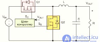
Let's move on to consider specific symptoms of PWM controller malfunctions.
Stopping immediately after starting
The pulse modulator starts but immediately stops. Possible reasons: open feedback circuit; the power supply is overloaded; The filter capacitors at the output are faulty.
Finding the problem: inspecting the board, looking for visible external damage; Using a multimeter to measure the supply voltage of the microcircuit, the voltage on the switches (at the gates and at the output), and on the output capacitors. In ohmmeter mode, use a multimeter to measure the load of the stabilizer and compare it with the typical value for similar circuits.
Pulse modulator does not start
Possible reasons: presence of a prohibiting signal at the corresponding input. Information should be found in the datasheet of the corresponding microcircuit. The malfunction may be in the power supply circuit of the PWM controller, or there may be internal damage in the microcircuit itself.
Steps to determine the malfunction: external inspection of the board, visual search for mechanical and electrical damage. To check, use a multimeter to measure the voltages on the pins of the microcircuit and check their compliance with the data in the datasheet; if necessary, you need to replace the PWM controller.
Voltage problems
The output voltage differs significantly from the nominal value. This can happen for the following reasons: a break or change in resistance in the feedback circuit; a fault inside the controller.
Troubleshooting: visual inspection of the circuit; checking the levels of control and output voltages and checking their values with the datasheet. If the input parameters are normal, but the output does not correspond to the nominal value, replace the PWM controller.
Disabling the power supply by protection
When the pulse-width modulator starts, the power supply is turned off by protection. When checking the key transistors, a short circuit is not detected. Such symptoms may indicate a malfunction of the PWM controller or key driver.
In this case, it is necessary to measure the resistance between the gate and source of the switches in each phase. A low resistance value may indicate a driver malfunction. If necessary, drivers are replaced.
The LNK304-306 microcircuits are designed to operate in low-power network power supplies without galvanic isolation; they are practically a more modern replacement for power supplies with a linear voltage stabilizer with a capacitance that absorbs excess voltage.
Features of the LNK304-306 IC are: minimum number of attached components; soft start; operation at a frequency of 66 kHz; precise limitation of output current; built-in generation frequency modulation; low consumption; ability to work without load.
The microcircuits are available in packages: DIP8 and SMD8 without the 6th pin (Fig. 1). The block diagram of the microcircuits is shown in Fig. 2. It contains an N-channel MOS transistor and a controller for controlling it. Stabilization of the output voltage is carried out by prohibiting the inclusion of the transistor of the microcircuit for some time, i.e. one or more cycles of converter operation are skipped. This is a significant difference between converters based on Link Switch-TN chips and similar devices that use pulse-width modulation.
Manufacturer's declared capabilities of power supplies based on LNK304-306 chips:
- Cost-effective replacement for linear/capacitive power supplies.
- Minimum cost and number of components.
- Built-in short circuit protection with automatic restart, overheating and open circuit protection.
- 66 kHz operation with precise current threshold, allowing the use of inexpensive 1 mH inductance for load currents up to 120 mA.
- High temperature stability
- High breakdown voltage 700V.
- Wide frequency range.
- Operation of a current limiting circuit with ripple suppression.
- Wide input voltage range (-85…265V).
- Higher efficiency. compared to passive schemes.
- SMD technology support
- Own consumption is no more than 50/80 mW at an input AC voltage of 115/230V without load.
Figure 3 shows the circuit of a power supply based on the LNK304 IC, which provides a stable output voltage of 5.07 V at a current of up to 120 mA.
The alternating voltage from the mains is supplied to a half-wave rectifier consisting of diodes D3, D4, capacitors C4, C5 and inductor L2. Resistor RF1 is both a fuse and a means of reducing the charging current through C4 and C5 when the circuit is connected to the mains.
So that the circuit can operate without load, resistor R4 is used.
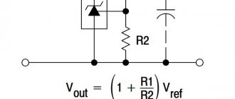
Stabilization is organized by supplying voltage from the output to the PB pin through a divider, so that at the rated output voltage at the PB pin there is 1.65V. Dependence of the output voltage on resistors R1 and R3:
Uout = 1.65(1 +R1/R3)
Figure 4 shows an example of a wiring diagram (shown not to scale).
Author: Karavkin V.
You might be interested in this:
Permanent link to this post: https://meandr.org/archives/32571