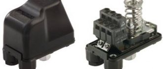
Modern apartments and houses are full of various electrical appliances :
- light sources of various powers and configurations,
- heating appliances,
- electric drives for curtains, blinds and many other devices.
At the same time, the methods we are accustomed to managing them can no longer be used due to technical limitations or due to customer requirements. This article discusses methods for regulating electrical devices using a pulse relay and a contactor .
Load control 220 volts WITHOUT relays! 58
Using optothyristors
Optosimistors MOS301x, MOS302x, MOS303x, MOS304x, MOS306x, MOS308x Optosimistors belong to the class of optocouplers and provide very good galvanic isolation (about 7500 V) between the control circuit and the load. These radioelements consist of an infrared LED connected via an optical channel to a bidirectional silicon triac. The latter can be supplemented with an unlocking circuit that is triggered when the supply voltage passes through zero. These radioelements are especially indispensable when controlling more powerful triacs, for example, when implementing high voltage or high power relays. Such optocouplers were conceived to communicate between logic circuits with low voltage levels and a load powered by a mains voltage of 220 V. The optosimistor can be placed in a small-sized DIP package with six pins; its pinout and internal structure are shown in Fig. 1.
The table shows the classification of optosimistors according to the magnitude of the forward current through the IFT LED, which opens the device, and the maximum forward repeating voltage that the triac can withstand at the output (VDRM). The table also notes the property of the triac to open when the supply voltage passes through zero. To reduce interference, it is preferable to use triacs that open when the supply voltage passes through zero.
As for elements with zero supply voltage detection, their output stage is triggered when the supply voltage exceeds a certain threshold, usually 5 V (maximum 20 V). The MOS301x and MOS302x series are more often used with resistive loads or in cases where the load supply voltage must be turned off. When a triac is in a conducting state, the maximum voltage drop across its terminals is usually 1.8V (maximum 3V) at a current of up to 100mA. The holding current (IH), which maintains the conductivity of the output stage of the optosimistor, is equal to 100 μA, whatever it is (negative or positive) during the half-cycle of the supply voltage. The off-state leakage current of the output stage (ID) varies depending on the optosimistor model. For optosimistors with zero detection, the leakage current can reach 0.5mA if the LED is energized (current flowing IF). The infrared LED has a reverse leakage current of 0.05 µA (maximum 100 µA), and a maximum forward voltage drop of 1.5 V for all optosimistor models. The maximum permissible LED reverse voltage is 3 volts for models MOS301x, MOS302x and MOS303x and 6 volts for models MOS304x. MOSZO6x and MOSZO8x. Maximum permissible characteristics The maximum permissible current through the LED in continuous mode is no more than 60mA. The maximum pulse current in the conducting state of the output stage switch is no more than 1 A. The total power dissipation of the optosimistor should not exceed 250 mW (maximum 120 mW for the LED and 150 mW for the output stage at T - 25˚C).
Application of optosimistors
Figure 2 a-e shows various diagrams of typical applications of optosimistors, differing from each other in the nature of the load and the methods of connecting the load and power. Resistance Rd The calculation of the resistance of this resistor depends on the minimum forward current of the infrared LED, which guarantees the triggering of the triac. Therefore, Rd = (+V - 1.5) / IF. For example, for a transistor control circuit for an optosimistor with a supply voltage of +5 V (Fig. 3) and an open transistor voltage (Uke us) equal to 0.3 V, +V will be 4.7 V, and IF should be in the range between 15 and 50 ma for MOS3041. You should take IF - 20 mA, taking into account the decrease in LED efficiency over the service life (5 mA reserve), fully ensuring the operation of the optocoupler with a gradual weakening of the current. Thus, we have: Rв = (4.7 - 1.5) / 0.02 = 160 Ohm. You should select a standard resistance value, that is, 150 Ohms for MOS3041 and a resistance of 100 Ohms for MOS3020. Resistance R Resistor R does not need to be included when the load is purely resistive. However, if the triac is protected by an RP - CP circuit, most often called a spark-extinguishing circuit, resistor R makes it possible to limit the current through the control electrode of the optosimistor. Indeed, in the case of an inductive load, the current passing through the triac and the voltage applied to the circuit are in antiphase. Since the triac ceases to be a conductor when the current passes through zero, the CP protection circuit capacitor can discharge through the optosimistor. Then resistor R limits this discharge current. The minimum value of its resistance depends on the maximum voltage of the capacitor and the maximum permissible current for the optosimistor, therefore for a supply voltage of 220 V: Rmin = 220 V x 1.41 / 1A - 311 Ohm. On the other hand, too large an R value can lead to malfunction. Therefore, they take R - 330 or 390 Ohms. Resistance RG Resistor RG is needed only when the input resistance of the control electrode is very high, that is, in the case of a sensitive triac. The value of resistor RG can be in the range from 100 to 500 ohms. Resistors RG and R introduce a delay in unlocking the triac, which will be more significant the higher the resistance of these resistors. Chain Ra - Ca To limit the rate of change of voltage dV/dt at the output of the optosimistor, a snubber chain is needed (Fig. 2 d). The choice of the value of the resistor Ra depends on the sensitivity of the triac and the voltage Va, starting from which the triac should operate. Thus, we have: R + Ra = Va / IG. For a triac with control current IG = 25mA and trigger voltage Va = 20V, we obtain: R + Ra = 20 / 0.025 - 800 Ohm or: Ra = 800 - 330 = 470 Ohm. In order for the triac to switch quickly, the following condition must be met: dV / dt = 311 / Ra x Ca. For MOS3020, the maximum dV / dt value is 10 V/µs. Thus: Ca = 311 / (470 x 107) = 66 nF. We choose: Ca = 68 nF. Comment. As for the snubber chain, experimental values are generally preferable to theoretical calculations. Protection It is strongly recommended to protect the triac and optosimistor when operating on an inductive load or when interference frequently affects the network. For a triac, a spark-extinguishing RC circuit is simply necessary. For an optosimistor with zero detection, such as the MOS3041, this is desirable. The resistance of resistor R should be increased from 27 Ohms to 330 Ohms (except for the case when the controlled triac is insensitive). If a model without zero detection is used, then the snubber chain Ra - Ca is required.
Electronics for everyone
| Triac BT139 |
| Connection diagram from datasheet on MOC3041 |
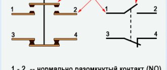
If you look at it on your fingers, then a thyristor is similar to a diode , even the designation is similar. It allows current to flow in one direction and does not allow it to flow in the other. But it has one feature that fundamentally distinguishes it from a diode - control input . If opening current , then the thyristor will not pass current even in the forward direction. But as soon as you give even a brief impulse, it immediately opens and remains open as long as there is direct voltage. If the voltage is removed or the polarity is changed, the thyristor will close .
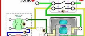
The polarity of the control voltage should preferably match the polarity of the anode voltage. If you connect two thyristors back-to-back in parallel , you get a triac - an excellent thing for switching loads on alternating current.
On the positive half-wave of the sinusoid one passes, on the negative half-wave the other. Moreover, they pass only if there is a control signal. If the control signal is removed, then in the next period both thyristors will shut down and the circuit will break. Beauty and nothing more. So it should be used to control household loads.
But there is one subtlety here - we are switching a high-voltage power circuit, 220 volts. And our controller is low-voltage , it operates at five volts. Therefore, in order to avoid excesses, it is necessary to make a potential decoupling . That is, make sure that there is no direct electrical connection between the high-voltage and low-voltage parts. For example, make optical separation . There is a special assembly for this - triac optodriver MOC3041 . Wonderful thing! Look at the connection diagram - just a few additional parts and you have the power and control parts separated from each other. The main thing is that the voltage for which the capacitor is designed is one and a half to two times higher than the voltage in the outlet. You don’t have to worry about power interference when you turn the triac on and off. In the optodriver itself, the signal is supplied by an LED, which means you can safely light it from the microcontroller pin without any additional tricks.
In general, it is possible without decoupling and it will also work, but it is considered good form to always make a potential decoupling between the power and control parts. This includes the reliability and safety of the entire system. Industrial solutions are simply filled with optocouplers or all sorts of isolating amplifiers.
BT139 as a triac - with a good radiator, this thing can easily carry a current of 16A through itself
Connecting the load to Arduino
Many beginners, after a few simple experiments with programmable Arduino microcontrollers, try to implement their own ideas, but are faced with a fairly common problem - connecting the load.
The fact is that at the Arduino outputs you can only get a voltage of 5 V (this is the logical one level). In this case, the current strength will be no more than 40 mA. Such parameters may not be sufficient for many external circuits and components. For example, 40 mA will not make most electric motors work, even those powered by 5 V.
Therefore, below we will consider options for connecting various types of loads.
The basic principle is to start/stop the external unit using the “one-zero” logical levels at the Arduino output. And it is best to provide protection for the microcontroller from voltage surges from the connected circuit.
Connecting weak loads
The simplest example is an LED. Most of these diodes have a current limit of 20 mA (0.02A). Therefore, it is best to connect them to Arduino through a current-limiting resistor. We looked at how to calculate it in a separate article; just in case, let’s recall the formula:
R=U/I
Here R is the resistance of the section of the circuit that includes both the limiting resistor and the diode itself (their resistances are added together). But since the diode’s own resistance is negligible, it can simply be ignored in this problem. Then we get:
Rolim = 5 V / 0.02 A = 250 Ohm.
That is, when a resistor with a value of over 250 Ohms is connected to the power circuit, we will get a current drop below 0.02 A (which is what is needed for an LED).
Similarly, you can calculate the current-limiting resistor for other elements.
A typical inclusion of low-power elements using the same LED as an example can be seen below.
Rice. 1. Typical inclusion of low-power elements using the example of an LED
Some models of Arduino boards can activate the built-in current limiting system, then the resistor may not even be needed.
Connecting high-power DC loads
Here it is necessary to stipulate separately that the external circuit must be powered from a different current/voltage source that corresponds to the nature of consumption.
Arduino can be connected to the control circuit through an intermediary, for example, through a transistor or similar circuit/element. Let's start with simple bipolar transistors.
Via bipolar transistor
The classic connection diagram will look like this.
Rice. 2. Classic switching circuit via a bipolar transistor
The value of the resistor connected to the base is given as an example. In fact, its value must be calculated in accordance with the performance characteristics of the transistor (the input voltage level depends on the gain in saturation mode and the supply voltage in the controlled circuit).
Almost any npn is suitable for the role of a transistor.
This circuit is easy to implement and affordable, but is not suitable for driving circuits with very powerful loads.
The alternative is below.
Via field effect transistor
Indeed, power circuits can be connected to Arduino via field devices.
A typical connection diagram looks like this.
Rice. 3. Classic connection circuit via a field-effect transistor
It is not worth using field-effect transistors with a low load, since, firstly, they are slow to switch, and secondly, they will get quite hot.
When connected to the gate, the same limiting resistor is used, which must be correctly calculated based on the power parameters and the characteristics of the field device itself.
And the second (10K) is used to protect the microcontroller itself and eliminate interference in the operation of the transistor (excludes the Z-state).
In the case of connecting motors or other reactive loads without protection, it is best to provide for reverse breakdown and install a diode. For example, like this. Despite the fact that diodes are often already built into modern field-effect transistors, in reality they do not always cope with the task.
Rice. 4. Inductive load
To increase the “controllability” of the circuit, it is best to choose mosfets marked “Logic Level” (they are designed to work with digital logic levels).
Through Darlington transistors
What is called an “out-of-the-box solution”. In radio stores you can find ready-made chips such as ULN2003, which are a set of independent composite Darlington transistors. The control scheme is implemented very simply.
Rice. 5. Control circuit
Here, each Arduino output controls a separate composite transistor (the output is strictly opposite). If necessary, the transistors can be connected in parallel (each “pulls” a load of 500 mA).
Via opto-relay
This is an almost ideal solution, devoid of many disadvantages associated with other methods.
Solid state relays provide complete galvanic isolation of the control circuit and the main circuit, they do not have any mechanical parts, they allow you to work with high currents, etc.
The connection diagram for the load with the opto-relay will look like this.
Rice. 6. Load connection diagram with opto-relay
The resistor in front of the relay is responsible for limiting the current. It is calculated as in the previous examples.
An opto-relay is not suitable only for cases of controlling “fast” circuits.
Other methods
Above we have outlined only the main methods used. In fact, there are many other methods for connecting powerful loads to Arduino and other microcontrollers:
1.Through semistors (triacs)
Rice. 7. Connecting powerful loads to Arduino and other microcontrollers via semistors
2.Through classic relays (another intermediary is required to control the relay itself)
Rice. 8. Connecting powerful loads to Arduino and other microcontrollers via classic relays
3.Switching with simultaneous stabilization
Rice. 9. Switching with simultaneous stabilization
4.Short circuit protected driver
Rice. 10. Short circuit proof driver
Author: RadioRadar