Three-phase voltage control relay EL-11, EL-12 and EL-13
EL-13 is used as protection for reversible electric drives with a power of no more than 75 (kW).
Now let’s take a closer look at each type of relay separately.
Technical characteristics of EL-11, EL-12 and EL-13
The technical specifications are shown in the table below (clicking on the picture will enlarge it).
This is a plate with data on the switching capacity of these relays.
And here are their overall dimensions.
Installation of phase control relays EL-11, EL-12 and EL-13
EL-11, EL-12 and EL-13 are attached in two ways. The first method of fastening is carried out using two M4 mounting screws.
The second mounting method is more convenient in my opinion - DIN rail mounting.
By the way, the passport for this relay says that it can have an arbitrary spatial position.
In general, at least install it “upside down”.
Connection and diagram of relay EL-11, EL-12 and EL-13
Connection of three-phase voltage control relays of types EL-11, EL-12 and EL-13 is carried out using wires under clamps. Under each terminal it is permissible to connect either one wire with a cross-section of 2.5 sq. mm, or two wires with a cross-section of up to 1.5 sq. mm.
I remind you that I have already written an article on the topic of how to determine the cross-section of a wire by its diameter. You can read it.
To connect everything correctly, you need to know the diagram. In principle, the manufacturers took care of the hint and depicted the connection diagrams on the relay body itself.
When connecting the relay, it is necessary to observe the correct order of phase alternation - A, B and C.
By the way, when checking this relay, I discovered that on the bench I had the reverse order of phase rotation of the three-phase voltage source. Instead of A, B, C, the terminals actually showed C, B, A.
One of these days I will mark the phases in the form of stickers.
So, for a more visual representation of the operation of this relay, I put together the following diagram.
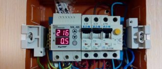
This is what the diagram looks like on the stand.
A three-phase voltage of ~ 110 (V) with correct phase rotation is supplied to the terminals (terminals) A, B, C of the EL-11 relay.
To observe the work of the weekend n.z. (1-2) and n.o. (3-4) relay contacts, I connected SKL LED lamps of red and green colors to them.
On N.Z. (normally closed) contact connected the green lamp, and on the no. (normally open) - red.
Operation of relays EL-11, EL-12 and EL-13
Let's consider several cases of operation of a three-phase voltage control relay.
1. No voltage at relay terminals A, B, C
If there is no three-phase supply voltage at relay terminals A, B, C, the red “network” LED does not light up. Contact (1-2) is closed, (3-4) is open. This is clearly visible from the lamps - the green lamp is on.
2. There is voltage at relay terminals A, B, C
When three-phase supply voltage is applied to relay terminals A, B, C, the red LED lights up. Contact (1-2) opens, (3-4) closes. Again, this is clearly visible from the lamp - the red lamp is on.
3. There is voltage at relay terminals A, B, C, but its parameters are outside the permissible limits
Let's consider the case when voltage is present at the terminals of the phase control relay A, B, C, but its parameters exceed the permissible values specified in the technical specifications. At this moment, the red LED on the front panel of the phase control relay goes out, and contact (1-2) closes and (3-4) opens after a period of time set using the regulator.
For relays EL-11, EL-12 and EL-13, the time delay can be adjusted in the range from 0.1 - 10 (sec).
After the network parameters are restored, the red LED on the front panel of the phase control relay lights up again, contact (1-2) opens, (3-4) closes, i.e. the scheme is restored.
As they say, “it’s better to see once than to hear a hundred times,” in general, watch the video about the principle of operation of this relay:
Addition: at the request of readers, I am posting functional diagrams of the relay.
We looked at phase control relays of types EL-11, EL-12 and EL-13. Now let's move on to their modernized “brothers” such as EL-11MT and EL-12MT.
Technical characteristics of EL-11MT and EL-12MT
Specifications:
And here are their overall dimensions.
Installation and connection of EL-11MT and EL-12MT
EL-11MT and EL-12MT are mounted either using two mounting screws or on a DIN rail.
Connection and diagram of relay EL-11MT and EL-12MT
Connection of three-phase voltage control relays of type EL-11MT and EL-12MT is carried out in the same way.
The only difference is the marking of the clamps. Instead of A, B, C, these relays use the markings L1, L2, L3. The same situation applies to contacts. Instead of n.z. contact (1-2) is used (11-12), and instead of n.o. (3-4) - (21-24).
In principle, the manufacturers again took care of a hint for electricians and drew a diagram for connecting the relay directly on its body.
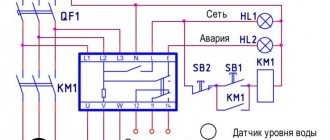
As an example, we depicted a motor protection circuit using a three-phase voltage control relay.
Now I’ll tell you how this scheme works.
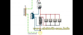
The electric motor is powered from a three-phase voltage network through fuses. After the fuses, a phase control relay EL-12MT and power contacts of the magnetic starter (contactor) KM are installed. The KM contactor is controlled as follows.
The power supply for the control circuits in this example is taken from two phases L1 and L2 (you can also take another line voltage). The KM contactor coil must be selected for line voltage, i.e. if the line voltage of the network is 380 (V), then the KM coil should be at 380 (V).
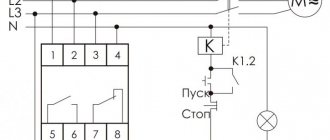
When you press the SB1 button, the KM contactor is turned on via the circuit: phase L1 - pressed button SB1 - normally closed contact of the SB2 button (stop) - closed contact (24-21) phase control relay EL-12MT - KM contactor coil - phase L2. There is no need to hold down the SB1 button, because when the KM contactor is triggered, the SB1 button is bypassed by its normally open contact KM.
Accordingly, contact EL-12MT (24-21) will be closed if the parameters of the three-phase supply network satisfy all the conditions stated at the beginning of this article.
For example, the engine is running normally. Suddenly, a phase of the three-phase supply voltage disappeared. After 2 (sec.) the relay will open contact (24-21), the KM contactor coil will de-energize and open its power KM contacts. The engine will be disconnected from the network.
When connecting relays EL-11MT and EL-12MT, it is necessary to observe the correct phase rotation order.
Three-phase voltage control relays of type EL-11MT and EL-12MT have slight differences from their predecessors.
1. Trip setpoint regulators for overvoltage and undervoltage
On the front panel of the relay there are 2 regulators for regulating the relay operation setting when the voltage of the three-phase supply network is exceeded and decreased.
You can see their limits in the technical specifications, which I wrote about just above.
2. Regulators for setting the time delay for overvoltage and undervoltage
Using these regulators, you can set a specific time delay for the relay to operate when the supply voltage is over and under. You will find all regulation limits for them in the technical specifications.
3. There are 3 red LEDs on the front panel of the relay
There are 3 red LEDs on the front panel. If one of the phases is broken or the phase sequence of the three-phase supply voltage is violated, the first LED lights up. By the way, I almost forgot to say that when there is a break or change in the phase sequence, the relay is triggered with a set (non-adjustable) time delay of 2 (sec).
When the voltage exceeds the setting, the second LED lights up. And vice versa, when the voltage drops below the set point, the third LED lights up. See table.
PS I think this is where we can stop at getting to know and studying EL-11, EL-12, EL-13, EL-11MT and EL-12MT. If you have any questions about these relays or need help connecting them, please write in the comments. And also, if you found the article useful, then share it with friends and colleagues on social networks. I will be very grateful to you.
Device and operation.
When a supply voltage is supplied with parameters within acceptable limits (phases A, B, C), the LED lights up green. In this case, contacts 1 and 2 open, and contacts 3 and 4 close. In case of unacceptable controlled parameters (phase failure, etc.), contacts 1 and 2 are closed, and contacts 3 and 4 are opened. The LED glows red in this situation.
When the network parameters return to normal, the relay returns to its original state.
Attention! When connected to a network with parameters outside the permissible limits, short-term (0.2...0.5 s) operation of the relay is possible.