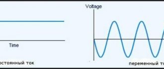
One of the most popular topologies of pulse voltage converters is a push-pull converter or push-pull (literally translated - push-pull).
Unlike a single-ended flyback converter, energy is not stored in the push-pool core, because in this case it is a transformer core, not an inductor core, it serves as a conductor for the alternating magnetic flux created in turn by the two halves of the primary winding .
However, despite the fact that this is a pulse transformer with a fixed transformation ratio, the stabilization voltage of the push-pull output can still be changed by varying the width of the operating pulses (using pulse width modulation).
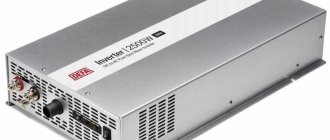
Due to their high efficiency (efficiency up to 95%) and the presence of galvanic isolation of the primary and secondary circuits, push-pull pulse converters are widely used in stabilizers and inverters with a power of 200 to 500 W (power supplies, automotive inverters, UPS, etc.)
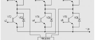
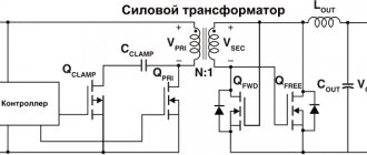
The figure below shows the general circuit of a typical push-pull converter. Both the primary and secondary windings have taps from the middle, so that in each of the two working half-cycles, when only one of the transistors is active, its half of the primary winding and the corresponding half of the secondary winding would be used, where the voltage would drop on only one of the two diodes.
The use of a full-wave rectifier with Schottky diodes at the output of a push-pull converter makes it possible to reduce active losses and increase efficiency, because it is economically much more expedient to wind two halves of the secondary winding than to incur losses (financial and active) with a diode bridge of four diodes.
The switches in the primary circuit of a push-pull converter (MOSFET or IGBT) must be designed for twice the supply voltage in order to withstand not only the source EMF, but also the additional effect of the EMF induced during each other's operation.
The features of the device and mode of operation of a push-pull circuit distinguish it favorably from half-bridge, forward and flyback circuits. Unlike the half-bridge, there is no need to decouple the key control circuit from the input voltage. A push-pull converter operates like two single-ended forward converters in one device.
In addition, unlike a forward converter, a spirit-cycle converter does not need a limiting winding, since one of the output diodes continues to conduct current even when the transistors are closed. Finally, unlike a flyback converter, in a push-pull converter the switches and magnetic circuit are used more sparingly, and the effective pulse duration is longer.
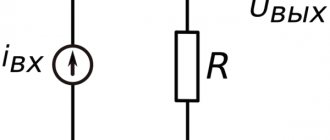
Push-pull current-controlled circuits are becoming increasingly popular in integrated power supplies for electronic devices. With this approach, the problem of increased voltage on the keys is completely eliminated. A shunt resistor is connected to the common source circuit of the switches, from which the feedback voltage is removed for current protection. Each cycle of operation of the switches is limited in duration by the moment the current reaches a given value. Under load, the output voltage is typically limited by PWM.
When designing a push-pull converter, special attention is paid to the selection of switches so that the open channel resistance and gate capacitance are as small as possible. To control the gates of field-effect transistors in a push-pull converter, gate driver microcircuits are most often used, which easily cope with their task even at frequencies of hundreds of kilohertz, typical of switching power supplies of any topology.
Source
How a class AB amplifier works (Push Pull) 02/19/2021 19:52
Class AB is the type of amplifier that, until recently, was used in Hi-Fi equipment many times more often than any other. Now the threatening shadow of class D amplifiers is already hanging over it, occupying an increasingly large share of the Hi-Fi market, but for now class AB models are still in the majority and they are not going to give up so easily. In the AB class, both tube and transistor circuits can work, but if we talk about the absolute majority, the AB class is more likely associated with the era of transistor Hi-Fi.
Implementation
The entire implementation was divided into two functions and constants:
- Two dedicated constants of type TIM_OCInitTypeDef and TIM_OCInitTypeDef2.
- Initialization with stop parameters. This is done so that after initialization the power supply does not start working. The launch is initiated by setting the function to the desired duty cycle value.
- Duty cycle adjustment function. It is important that the duty cycle value is lower than 0.45.
Everything is implemented using SPL libraries. Of course, I have plans to rewrite it later under CMSIS, but for now I decided to draft it under SPL the old fashioned way.
Initialization with comments:
void PWM_Out() { GPIO_InitTypeDef port; TIM_TimeBaseInitTypeDef TIM_TimeBaseStructure; //Port init for working with PWM RCC_APB2PeriphClockCmd(RCC_APB2Periph_GPIOA, ENABLE); port.GPIO_Mode = GPIO_Mode_AF_PP; port.GPIO_Pin = (GPIO_Pin_6 | GPIO_Pin_7); port.GPIO_Speed = GPIO_Speed_50MHz; GPIO_Init(GPIOA, &port); RCC_APB2PeriphClockCmd(RCC_APB2Periph_GPIOB, ENABLE); port.GPIO_Mode = GPIO_Mode_AF_PP; port.GPIO_Pin = (GPIO_Pin_0|GPIO_Pin_1); port.GPIO_Speed = GPIO_Speed_50MHz; GPIO_Init(GPIOB, &port); // Global TIM Init RCC_APB1PeriphClockCmd(RCC_APB1Periph_TIM3, ENABLE); TIM_TimeBaseStructure.TIM_Prescaler = 0; TIM_TimeBaseStructure.TIM_CounterMode = TIM_CounterMode_CenterAligned1; //this is the main string. It configures TIM3 for synchronization signal center TIM_TimeBaseStructure.TIM_Period = 1000; // this if durty cycle. It must be less then 0.45 TIM_TimeBaseStructure.TIM_ClockDivision = 0; TIM_TimeBaseStructure.TIM_RepetitionCounter = 0; TIM_TimeBaseInit(TIM3, &TIM_TimeBaseStructure); //Init LINE 1 TIM_OCInitStructure.TIM_OCMode = TIM_OCMode_PWM1; TIM_OCInitStructure.TIM_OutputState = TIM_OutputState_Enable; TIM_OCInitStructure.TIM_OutputNState = TIM_OutputNState_Enable; TIM_OCInitStructure.TIM_OCPolarity = TIM_OCPolarity_High; TIM_OCInitStructure.TIM_OCNPolarity = TIM_OCNPolarity_High; TIM_OCInitStructure.TIM_OCIdleState = TIM_OCIdleState_Set; TIM_OCInitStructure.TIM_OCNIdleState = TIM_OCNIdleState_Reset; //——start value of PWM————— TIM_OCInitStructure.TIM_Pulse= 0; TIM_OC4Init(TIM3, &TIM_OCInitStructure); //Init LINE 1 TIM_OCInitStructure2.TIM_OCMode = TIM_OCMode_PWM1; TIM_OCInitStructure2.TIM_OutputState = TIM_OutputState_Enable; TIM_OCInitStructure2.TIM_OutputNState = TIM_OutputNState_Enable; TIM_OCInitStructure2.TIM_OCPolarity = TIM_OCPolarity_Low; TIM_OCInitStructure2.TIM_OCNPolarity = TIM_OCNPolarity_Low; TIM_OCInitStructure2.TIM_OCIdleState = TIM_OCIdleState_Set; TIM_OCInitStructure2.TIM_OCNIdleState = TIM_OCNIdleState_Reset; TIM_OCInitStructure2.TIM_Pulse= 1000; TIM_OC3Init(TIM3, &TIM_OCInitStructure2); TIM_OC2Init(TIM3, &TIM_OCInitStructure2); TIM_OC1Init(TIM3, &TIM_OCInitStructure2); /* TIM3 counter enable */ TIM_Cmd(TIM3, ENABLE); /* TIM3 Main Output Enable */ TIM_CtrlPWMOutputs(TIM3, ENABLE); }
And a simple adjustment function:
void set_pwm(int pwm) //till 1000 { TIM_Cmd(TIM3, DISABLE); TIM_OCInitStructure.TIM_Pulse = pwm; TIM_OCInitStructure2.TIM_Pulse = 1000 - pwm; TIM_OC3Init(TIM3, &TIM_OCInitStructure2); TIM_OC4Init(TIM3, &TIM_OCInitStructure); TIM_Cmd(TIM3, ENABLE); }
Of course, you can add protection against exceeding 0.45 of the maximum value, but if we consider it in the general case, then this code is quite sufficient. Of course, the finished power supply must provide for this to one degree or another.
Principle of operation
From the very designation of class AB, it is easy to conclude that this mode is a hybrid of class A and class B. We have already figured out how class A amplifiers work, but we did not have time to familiarize ourselves with class B, so we will start with it. And to begin with, let us remember the logic that guided the creator of the class A amplifier. In order to be able to reproduce both positive and negative half-waves using one active element, he applied a shift of the midpoint (quiescent current) to the middle of the working area of the lamp.
The creators of Class B amplifiers reasoned differently: “If one tube or one zero-bias transistor can reproduce only one half-wave of the signal, why not add another active element to the circuit, placing it in a mirror, to reproduce the other half-wave?”
This is quite logical, because in this situation both transistors operate with zero bias. As long as there is a positive half-wave at the input of the amplifier, one transistor works, and when the time comes to reproduce the negative half-wave, the first transistor is completely closed and the second one switches on instead. In the English version, this operating principle is called push-pull or, in Russian, “pull-push,” which in general describes what is happening very well.
When comparing Class B to Class A, the most obvious advantage is that in Class B, each wavelength covers the full operating range of the transistor (or tube), while in Class A, both half-waves are reproduced by a single active element. This means that a class B amplifier will be twice as powerful as a class A amplifier assembled using the same transistors.
The second, slightly less obvious, but very important advantage of class B is zero bias currents. When the input signal is zero, the current flowing through the transistors is also zero, which means that there is no wasted energy consumption, and the energy efficiency of the circuit is several times higher than in class A.
However, the main drawback of a class B amplifier follows from this same fact. The moment the transistor is turned on after a completely closed state is accompanied by a slight delay, therefore, when the sound signal passes the zero point, when one transistor has already closed, the second transistor does not have time to instantly pick up the baton, and in At this very transition point, small time delays occur.
In practice, this is expressed in the amplifier’s particular dislike for quiet music, as well as in poor transmission of microdynamics. And although history knows successful implementations of class B, for example, the legendary Quad 405, the problems of this operating mode have not gone away. The same 405 not only pleased with its energetic and muscular sound, but also had a clear tendency to paint a sound picture with large strokes, on a large scale, without wasting time on trifles.
In order to preserve all the advantages of class B and solve the problem of transient processes, the engineers resorted to a trick. They turned on both transistors with a bias, as is done in class A, but the bias value was chosen to be significantly smaller: so as to cover only those moments when the transistor is close to closing, thereby removing transient processes from the working area.
This allowed the class AB amplifier to quietly overcome the zero point, and also provided another extremely useful effect. When the signal amplitude is small, falling within the limits of the quiescent current bias, such an amplifier operates in class A and only when the amplitude goes beyond the bias value selected by the manufacturer does it switch to AB mode.
Iron
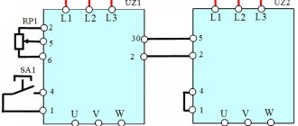
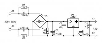
It just so happened that power boards have to be installed with enviable consistency, so with a little thinking, using components that were in bulk from old projects, a simple debugging board was assembled to check the calculations and prepare for the “big project”. The circuit is shown in Fig. 1, the board layout in Fig. 2, and the resulting appearance in Fig. 3.
Fig.1. Circuit description of the debug board
Fig.2. PCB layout
Fig.3. Three-dimensional model of the development board
The board was manufactured using the LUT method. There is nothing complicated or unusual in it, except, perhaps, for the operating frequencies: the signal rise time is less than 0.3 μs at an operating frequency of 24 kHz. For a switching power supply this is a tiny value, but it was enough for the author. Radiators for field-effect transistors IRFZ44N were not required, since the diodes in the circuit would overheat much faster.
I honestly admit that this board burned out under a load of only 80 W. So if you want to repeat every detail with your developments, then be careful. But in fact, the maximum current in this device of 10 amperes required the presence of a small radiator on transistors, as well as a reduction in frequency (load on the diodes).
pros
It makes sense to consider the advantages and disadvantages of the AB class against the backdrop of the two initial technologies. Class AB clearly and significantly outperforms class A in terms of energy efficiency. Its real efficiency reaches 70–80%, unless of course the manufacturer is too keen on raising the quiescent current. From a sound standpoint, Class AB is superior to Class A when the signal reaches high amplitude or high power is required. At the same time, at low volume levels, class AB is not inferior to ordinary class A, at least in theory. Compared to class B, class AB behaves much better at low volumes and is able to handle the quietest and most delicate moments in music, but at the same time retains almost the same power and strength at large dynamic bursts.
Having more power and better energy efficiency, class AB amplifiers are much less capricious when choosing acoustics. They do not require high sensitivity and are more easily compatible with complex crossovers used in multi-way speakers. It would be fair to say that the vast majority of passive speaker systems on the market today are designed to work with the average class AB transistor amplifier.
Minuses
The objective disadvantages of class AB can only be seen against the background of even more technically advanced classes G, H or D, which we will talk about a little later. The list of complaints can only include subjective reviews from class A connoisseurs, which, in general, boil down to the fact that class AB does not sound as clean, detailed and refined. To assess the validity of these claims, let's look at the circuitry of class AB amplifiers in more detail, from the point of view of sound quality.
Peculiarities
One of the practical problems of class B and AB amplifiers is the selection of pairs of transistors operating in the same amplification channel. Being positioned mirror-like in the circuit, the two transistors must be completely identical to each other. Otherwise, the signals of the positive and negative half-waves will not be reproduced symmetrically, and this will significantly increase the overall level of distortion.
In real life, absolute identity is an abstract concept; it makes more sense to talk about the degree of similarity or, in technical language, about the limits of permissible deviations of transistors from given characteristics. The more similar two transistors are to each other, the lower the level of distortion, and the more their joint work approaches what we have in class A, when both half-waves are reproduced by one transistor.
Understanding that even with the most stringent selection of parameters, differences between two transistors in a pair will still occur (albeit in extremely small values), we are forced to admit that, other things being equal, one of the same transistor operating in class A will sound slightly cleaner and slightly better than a pair in class AB.
A completely different situation emerges when it comes to working with a large signal amplitude and a load requiring high power. Having high efficiency, class AB requires a less powerful and bulky power supply than a class A amplifier, and here fans of single-ended amplifiers are forced to admit the absolute and unconditional superiority of class AB.
Moreover, developers have the opportunity to experiment much more freely with power supplies, controlling the character and dynamics of the sound by selecting the operating characteristics of the transformer and capacitors. For example, you can install a transformer with multiple power reserves so that during signal peaks it does not leave the optimal operating mode, or use improved capacitors that can instantly deliver high current.
Another subtlety: when operating in class A, transistors generate a large amount of heat, which can negatively affect the quality of their work, especially when the load increases. In class AB, transistors heat up to a lesser extent, as a result of which they quickly return to operating mode and are less susceptible to the risk of overheating, which reduces sound quality when the amplifier operates at high volumes.
Controller
All this was connected to our own debugging board based on STM32F103C8T6. Of course, you can use Chinese analogues, but since I work a lot on these chips, I needed a board to perfect the circuitry for connecting this chip + decent wiring of the analog part was required, which the Chinese brothers usually lack. The appearance of the board is shown in Fig. 4.
Fig.4. Development board based on STM32F103 of our own design
The power section was connected to PB0 and PB1, which are the outputs of the 3rd timer. This is a general purpose timer. The most common timer. It was chosen simply because of its convenient location on the board. What is described below can be easily done on any other timer, up to TIM1 (Advanced-control timer).
Practice
Defending the honor of class AB amplifiers in comparative listening was destined to the powerful two-block amplifier Atoll Signature series, consisting of an AM200 power amplifier and a PR300 preamplifier. The power amplifier we are interested in is built in full accordance with the theoretical calculations outlined above.
Realizing the potential inherent in class AB circuitry, the developers have provided 120 W of output power per channel, which is enough for most speaker systems except the most low-sensitive and simply monstrous models. Speaking about the features of its amplifier, the manufacturer focuses on the use of selected pairs of transistors, followed by manual adjustment of the circuit to minimize the overall level of distortion.
In order to better separate the channels and eliminate crosstalk, the amplifier is built according to a full dual mono circuit, so each amplification channel has its own power supply. The total power of the power supply is 670 VA, which covers the needs of a 120 W amplifier with a large margin. Solid additional power at signal peaks will be provided by capacitors with a capacity of 62,000 μF.
Introduction
It just so happened that an interesting topic at the university required me to assemble an interesting switching power supply. Up to this point, the author has already assembled single-ended converters many times: forward and flyback, based on the STM32F031 and STM32F103 microcontrollers and his own printed circuit boards. But then the question arose with push-pull converters, which require fundamentally different control, which initially puzzled us. The solution to a number of problems that the author encountered is given in this article.
Sound
The impressive power and excellent energy efficiency of the amplifier gave the sound the expected feeling of lightness and ease when working with any acoustics and at almost any volume level. If you turn the volume knob up, you can hear a little compression and the bass seemed to take a backseat, but these were clear signs that the woofers were nearing their limits, while the amp was just starting to warm up and was very far from being overload.
At the same time, the Atoll AM200 Signature performed best at low and medium volume levels. The midrange was expressive, detail was excellent, and the stage was clearly defined, with well-perceived depth and width. In direct comparison with Class A amplifiers, the latter gave a slightly freer and more limitless stage and worked out fine details in quiet chamber music a little more subtly.
The character characteristic of the AB class was most clearly manifested in the Atoll AM200 Signature on dynamic rock music. It produced very focused, fast and clear bass, handling sudden volume changes and large strokes well. On jazz and classical music, which require a combination of dynamics and power with the ability to reproduce subtle shades and nuances, the amplifier behaved a little less confidently. It seemed that he was slightly simplifying the sound, enlarging the musical images and drawing attention away from subtle shades to the main melodic line.
However, all this can only be noticed in direct comparison with much more expensive representatives of other classes. The overall impression was that the Atoll AM200 Signature was rather omnivorous and versatile. Being an example of a competent implementation of the AB class, when the developers made a lot of effort to minimize weak points and maximize the potential of this circuit design, it is quite competitive against the background of the best representatives of other classes.
Programming
First, I had to overclock the controller to 48 MHz. This was done with the following piece of code:
void Rcc_INIT_new() { //PLL RCC->CFGR &= ~RCC_CFGR_PLLSRC; RCC->CR &= ~RCC_CR_PLLON; RCC->CFGR &= ~RCC_CFGR_SW;; RCC->CFGR |= RCC_CFGR_SW_PLL; RCC->CFGR &= ~RCC_CFGR_PLLMULL; RCC->CFGR |= RCC_CFGR_PLLMULL12; RCC->CR |= RCC_CR_PLLON; while((RCC->CR & RCC_CR_PLLRDY)==0) {} }
Of course, you can describe what each line above means, but domestic sites are simply littered with this, let’s devote time to more unique things. Let us note, for those who are too lazy to go through forums and “training sites”, that the main adjustment is made by setting RCC_CFGR_PLLMULL(X).
Then the next, and actually the main problem arose, rather poorly described on the domestic Internet: the creation of pulses of the form shown in Fig. 5.
Fig.5. Required pulse shape for push-pull converter.
All descriptions of working with timers have a significant drawback: they begin (end) the edge of the signal synchronously with the zero of the timer operation. In this type of converters (push-pull), this is completely unacceptable. As a result:
- I didn’t want to make any fuss to control the power part (it means adding good mathematics to the controller to process the parameters)
- Public examples of using timers in PWM mode do not allow making the desired pulse shapes, unless, of course, you reconfigure the timer each time.
As a result, we opened the PWM manual and found the following wonderful thing: synchronization of PWM pulses to the center. This is exactly what you need, as it allows you to make impulses as follows + the adjustment is very convenient (see Fig. 6). If configured correctly, you will actually have to keep two PWM channel settings, since one channel should be direct and the other inverse. This will of course require memory, but not much.
Fig.6. The shape of the pulses when synchronized at the center of the pulse. The shaded areas are those that are added as the pulse time increases.
As is easy to see, an important rule remains: half the period between the beginnings of pulses in the lines. A similar principle works with any push-pull converters: half-bridge and bridge.
conclusions
High power, high efficiency with moderate heat dissipation, the ability to cope with complex loads and good dynamics - this is what an AB class amplifier is. This makes it, first of all, an ideal solution for mass production of amplifiers, as confirmed by the very history of the development of the Hi-Fi industry.
However, it is extremely erroneous to be guided by the stereotypical opinion that a mass universal product and an elite product must necessarily be molded from different cloth. With proper attention to detail and a deep understanding of operating principles, this circuit design can be implemented at the highest level of quality. So today, a high-end amplifier operating in class AB is as commonplace as a high-end amplifier operating in any other circuit design.
https://stereo.ru/