Single-phase voltage control relays, part 4 - Meander UZM-51M (2019)
Continuation of the series of reviews about single-phase voltage control relays, started here: Part 0 - UZM-51M Part 1 - PH-260t Part 2 - UZM-50Ts Part 3 - UZM-51M (2018) “Now I love you, now I praise you I" (Korney Chukovsky) No, Meander hasn’t bribed me yet, it’s just that the device turned out to be quite normal. This relay was sent by a colleague to be tested with passion, which is what I’ll actually do. As it turned out, in this voltage control relay the manufacturer has eliminated many critical shortcomings of previous versions. Currently, it is this version of the UZM-51M that is being produced and sold in some places. Attention!
When purchasing, pay attention that the LEDs are at the bottom, the terminals have curtains and the busbars are bare copper. Manufacturer Passport
Everything is sold in the same unified box with a window.
The package includes the device itself and a passport in Russian. The body of the device has been changed again, now the LEDs have crawled down. Unfortunately, the date on the case is not indicated (why would that be?), there is a sticker on the box -02.19- i.e. February 2022 The body is glossy gray, still does not support combustion, the inscriptions are painted
The terminals are clearly different, more about them below
It can be disassembled just as easily as the previous modification - with self-tapping screws. One under the latch, the second under the seal.
Immediately striking is the absence of insulating cardboard, a copper zero bus of a larger cross-section hard-soldered onto the board, and reinforced power connection terminals with M6 screws. Protective curtains have finally appeared on the terminals, preventing the wire from being connected past the terminal. This is a really useful device for inexperienced electricians and ordinary consumers. The design of the device itself is quite technological, it’s a pleasure to assemble and disassemble, I liked it
The printed circuit board was also changed
The relay was installed new at 80A, with a shunt and powerful busbars.
A raccoon hid under the varistor
The varistors themselves could be additionally heat-shrinked.
Storage capacitor.
Controller PIC12F683
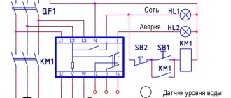
Electrical circuit diagram
The power relay was supplied with a new MP26 with reinforced busbars and a built-in 0.3 mOhm current-measuring shunt, which is not used in any way in this device. The zero bus is apparently not made of high-purity electrical copper, so its surface is quite heavily oxidized. It practically does not affect the work, but it does not look very aesthetically pleasing. Meander
, coat your tires to protect them from oxidation.
The actual cross-section of this tire is 8x1.4mm=11mm^2, which is more than enough. The power relay buses are clearly made of copper of a higher class and have a clean, shiny surface. + Resistor R1 was installed in a normal output version of sufficient power + Transistors VT3 and VT4 were supplied with normal, proven BSS123 + R20 was removed, now the yellow output voltage control LED is powered through R13 and R16. The solution is quite acceptable. — For some reason, they reduced the brightness of the green and red LEDs (HL1 - R21 and HL2 - R24). Agree that it is a little strange to supply a current of only 0.035 mA to the LED through a 100 kOhm resistor. Most likely, the resistor values were mixed up at production. It would be better to leave the brightness as it was because now the LEDs are really hard to see when installing the shield externally. I changed these resistors to 30kOhm and 10kOhm as they were in previous versions, now the brightness is normal. Square wave
, return the brightness back to how it was - The 0.1 µF shunt capacitor was not traditionally installed at the DA1 input, I added it myself. All changes circled
There are no more changes.
The UZM-51M withstood a short-term voltage of 480V normally. Long-term supply of 440V did not reveal any problems. The measuring stand has undergone some changes, now the increased voltage is supplied in a sharp jump and it is possible to more accurately track the response time of the protection. Voltage divider at the oscilloscope input 1:15 (full scale 600V), sweep 5ms/div, relay setting 175/265, supplied control voltage 220V/400V
As a result, the software part was also improved, now the shutdown time has become noticeably faster - from 15ms to 35ms, depending on the moment the increased voltage is applied. This speed is quite sufficient for reliable protection of any equipment. It is clearly seen that only the positive half-wave of the mains voltage is analyzed, which triggers the protection. This is why there is such a large variation in the relay response time. The relay always turns off at the decline of the half-wave, which is the correct solution. The speed of response to low mains voltage is not so critical, so there was no point in checking it with an oscilloscope.
Conclusion: I personally liked this device and I can recommend it for purchase. All detected minor defects are not critical and do not reduce the level of reliability and safety of the device. As usual, it didn’t turn out perfect, we’re waiting for the next versions...
To be continued, RBUZ is next...
Purpose of UZM-51MD
The abbreviated name UZM stands for multifunctional protective device, and the symbol “D” in the marking means the possibility of protection against sparking when an electric arc occurs.
The device performs a standard protective function during voltage surges and surges in single-phase electrical networks. The presence of a varistor allows you to cope with surge voltages that arise under the influence of powerful equipment located nearby. Thus, the entire operation of the device is to protect electrical appliances and equipment, preventing ignition that turns into a fire.
The main properties of UZM are the following:
- Protects home and other networks from negative phenomena associated with sparking and electric arcs.
- Can be used in networks with any configuration, with various connection schemes, with or without grounding.
- Performs its own tasks and cannot serve as a replacement for conventional protective devices - automatic machines, RCDs and others.
- Does not respond to short-term voltage dips lasting no more than 0.5 seconds. In such cases, the load is not disconnected and remains in operation.
- Protection against overvoltage and voltage sags in two levels with corresponding time delays.
- The presence of varistor protection allows you to effectively combat pulsed voltage surges.
- Ability to configure the turn-on delay for the required period of time.
Principle of operation
The UZM-51MD protective device operates according to the following algorithm. A 5-second time interval is maintained between the moment the voltage is applied and the transition to the ready mode. During this period, all indicators are turned off. If after checking the voltage is determined to be acceptable, the upper normal-failure indicator will flash green. From the time this LED turns on, a time delay begins, set by default to 10 seconds. After this, the load will be connected to the supply voltage. Switching on can be accelerated using the on-off button, which provides manual control.
In the event of an emergency shutdown, subsequent switching is performed automatically after normal voltage parameters are restored. There is also a delay of 10 s or 6 minutes. In the event of an accident, the load will not be able to be connected manually, since the relay will not allow this.
After establishing normal operating mode, the UZM monitors the voltage and parameters of the network with the connected load. With the advent of high-voltage pulse voltage, a varistor comes into operation, shunting it to levels that are not dangerous for the equipment.
If the voltage deviates from the operating limits, a delay begins to count, after which the load is turned off. For the upper limit it is 0.2 seconds, for the lower limit it is 10 seconds. If during these periods of time the voltage returns to the specified values, the time count will be reset and the load will not be disconnected.
When a spark or arc is detected in the network that exceeds safe operating limits in duration, the load will be switched off in emergency mode. Both the upper and lower indicators will light red. After 30 seconds the device will try to reconnect the load. If, after switching on for 20 minutes, signs of sparking are again detected, the load will be turned off again, but for 4 minutes. For the third time, the device completely disconnects the load until the fault is eliminated. After this, the load can only be turned on in manual mode.
Characteristics
Knowledge of the parameters and characteristics will allow you to use the UZM-51MD with maximum efficiency.
When choosing a device, you should pay attention to the following indicators, and then carefully study the instructions, where they are displayed in more detail:
- With a current interference of 100A, the device is capable of limiting the voltage to no higher than 1.2 kV.
- The maximum energy absorption capacity of a single pulse of 10/1000 μs is 200 J.
- Surge protection must operate within 25 ns or less.
- Load cut-off thresholds at high voltage, manually set - from 240 to 290 volts.
- Accelerated load shedding is performed at a critical upper voltage threshold - 300 V, plus or minus 15 volts.
- The lower shutdown limits, set manually, are from 210 to 100 volts.
- Accelerated shutdown, performed when the lower voltage limit drops to a critical state - 80 V, plus or minus 10 volts.
The device itself operates at the following parameters: rated supply voltage 230 volts, with a frequency of 50 Hz. The maximum value of the supply voltage is no more than 440 V. Consumption to maintain operability is: electricity - 1.5 Wh, power - 1.5 VA.
The UZM-51MD Meander device has contacts with good switching abilities. The rated load current is 63 A, provided that copper conductors with a cross-sectional area of at least 16 mm2 are connected. The rated load power at a voltage of 250V is 14.5 A. The maximum load current that can be withstood for 30 minutes without consequences is 80 A. Under the same conditions, the maximum load power is 20 kW. The maximum permissible short circuit current is 4500 A.
The operating temperatures at which the protective device can operate are in the following ranges: in the UHL2 version - from -25 to +55 degrees, in the UZM-51MD UHL4 version - from -40 to +55 degrees. The protection of the housing and terminals of the voltage relay has a degree corresponding to IP40 and IP0. The dimensions of the UZM 51MD are considered standard and are 83x35x67 mm, the weight does not exceed 160 grams. The device is designed for round-the-clock operation, the total service life declared by the manufacturer is 10 years.
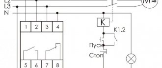
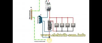
Connection diagram UZM-51MD
As already noted, a typical connection diagram is located on the side of the device. However, in practice, different situations arise in connection with the use of the device in certain places. In some cases, it is installed at the entrance after the input circuit breakers and the electricity meter. Another option involves installing UZM-51MD Meander indoors on separate lines that require special control. The presence of a fire protection RCD and other traditional means of protection should be taken into account.
In three-phase networks, these devices are used only in the absence of a three-phase load. That is, they are installed individually for each phase. In the event of an emergency shutdown of one of them, the others will continue to operate and provide power to the load. This is their main advantage over three-phase devices UZM-3-63, when triggered, all three phases are switched off. In all cases, in the absence of experience, it is recommended to discuss installation and connection issues with a qualified electrical engineer.