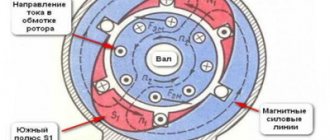
Rice. 1 Motor connection diagram for a single-phase asynchronous motor with a starting capacitor.
Let's take as a basis an already connected single-phase asynchronous motor with a clockwise rotation direction (Fig. 1).
- points A, B conventionally indicate the beginning and end of the starting winding; for clarity, brown and green wires are connected to these points, respectively.
- Points C and B conventionally indicate the beginning and end of the working winding; for clarity, red and blue wires are connected to these points, respectively.
- arrows indicate the direction of rotation of the rotor of an asynchronous motor
Task.
Change the direction of rotation of the single-phase asynchronous motor in the other direction - counterclockwise. To do this, it is enough to reconnect one of the windings of a single-phase asynchronous motor - either working or starting.
Option #1
We change the direction of rotation of a single-phase asynchronous motor by reconnecting the working winding.
Fig.2 With this connection of the working winding, relative to Fig. 1, single phase induction motor will rotate in the opposite direction.
Option No. 2
We change the direction of rotation of a single-phase asynchronous motor by reconnecting the starting winding.
Fig.3 With this connection of the starting winding, relative to Fig. 1, single phase induction motor will rotate in the opposite direction.
Important note.
This method of changing the direction of rotation of a single-phase asynchronous motor is possible only if the motor has separate taps of the starting and operating windings.
Fig.4 With this connection of the motor windings, reverse is impossible.
In Fig. Figure 4 shows a fairly common version of a single-phase asynchronous motor, in which the ends of windings B and C, the green and red wires, respectively, are connected inside the housing. Such a motor has three terminals, instead of four as in Fig. 4 brown, purple, blue wire.
UPD 09/03/2014 Finally, I was able to test in practice a not very correct, but still used method of changing the direction of rotation of an asynchronous motor. For a single-phase asynchronous motor, which has only three terminals, it is possible to make the rotor rotate in the opposite direction by simply swapping the run and start windings. The principle of such inclusion is shown in Fig. 5
Rice. Non-standard reverse of an asynchronous motor
The manufacture of homemade machines and mechanisms requires a torque source capable of developing high mechanical power on the drive shaft when powered from a 220-volt network.
An electric motor from a concrete mixer, washing machine, other equipment, or simply purchased on sale is suitable for these purposes.
In the article I tell you everything about a single-phase asynchronous motor, the connection diagram of which depends on the internal design and can be made with a starting winding or capacitor starting.
Subscribe to the newsletter
In order for mechanisms in production or at home, be it wood or metalworking machines, a cantilever pump, a conveyor belt, a crane beam, a sharpening machine, an electric lawn mower, a feed chopper or another device to work without breakdowns, it is necessary, first of all, for the electric motor shaft to rotate in the right direction.
In order to avoid mistakes and prevent rotation of the mechanism shaft in the opposite direction, in accordance with paragraph 2.5.3 of the “Rules for the technical operation of consumer electrical installations,” arrows in the direction of rotation of the electric motor .
Motor shaft rotation direction
The direction of rotation of the electric motor is determined from the single end of the shaft. If the engine has two shaft ends, then rotation is determined from the side of the shaft, which has a larger diameter. According to GOST 26772-85, the right direction corresponds to clockwise shaft movement. For the most common three-phase motors with a squirrel-cage rotor, the shaft will rotate to the right if the sequence of phases through which voltage is supplied to the ends of the stator windings corresponds to the alphabetical sequence of their markings - U1, V1, W1.
Right hand rotation
For single-phase motors with a squirrel-cage rotor, the shaft will rotate clockwise when the phase is supplied to the end of the working winding.
Changing the direction of shaft rotation in three-phase electric motors
The operation of some mechanisms requires left-hand rotation of the shaft. Knowing how to change the direction of rotation of an electric motor , this can be done without any modification or alteration of the drive motor itself. To change the direction of movement you need:
- de-energize the electric motor;
- remove the terminal box cover;
- rearrange the cores of the power cable in accordance with the diagram shown in Fig. 3: reconnect the black insulated wire (L3) to pin V1 in the terminal box, and reconnect the brown wire (L2) to pin W1.
Left-hand rotation
If the operation of the engine requires constant switching of the engine from right-hand rotation to left-hand rotation, its connection is carried out according to a special circuit,
Reversing a single-phase electric motor
You can start the rotation of a single-phase asynchronous electric motor by reconnecting the phase to the beginning of the working winding.
Knowing how to change the direction of rotation of an electric motor, you can connect a single-phase electric motor with the ability to switch from right-hand rotation to left-hand rotation using a three-pin switch.
Asynchronous electric motors
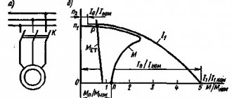
In previous sections, we discussed why AC motors are also called induction motors, or squirrel wheel motors. Next, we will explain why they are also called asynchronous electric motors. In this case, the relationship between the number of poles and the number of revolutions made by the rotor of the electric motor is taken into account.
The rotation frequency of the magnetic field is generally considered to be the synchronous rotation frequency (Ns). The synchronous speed can be calculated as follows: line frequency (F) multiplied by 120 and divided by the number of poles (P).
If, for example, the mains frequency is 50 Hz, then the synchronous speed for a 2-pole electric motor is 3000 rpm.
The synchronous speed decreases as the number of poles increases.
The table below shows the synchronous speed for different numbers of poles. Synchronous speed for different number of poles
| Number of poles | Synchronous speed 50 Hz | Synchronous speed 60 Hz |
| 2 | 3000 | 3600 |
| 4 | 1500 | 1800 |
| 6 | 1000 | 1200 |
| 8 | 750 | 900 |
| 12 | 500 | 600 |
Formulation of the problem
Let's assume that an asynchronous single-phase motor, already connected using a starting-charging capacity, initially has a shaft rotation directed clockwise, as in the picture below.
Let's clarify the important points:
- Point A marks the beginning of the starting winding, and point B marks its end. A brown wire is connected to the starting terminal A, and a green wire is connected to the ending terminal.
- Point C marks the beginning of the working winding, and point D marks its end. A red wire is connected to the initial contact, and a blue wire is connected to the final contact.
- The direction of rotation of the rotor is indicated by arrows.
We set ourselves the task of reversing a single-phase motor without opening its housing so that the rotor begins to rotate in the other direction (in this example, against the movement of the clock hand). It can be solved in three ways. Let's take a closer look at them.
Option 1: reconnecting the working winding
To change the direction of rotation of the motor, you can only swap the beginning and end of the working (permanently on) winding, as shown in the figure. You might think that to do this you would have to open the case, take out the winding and turn it over. There is no need to do this, because it is enough to work with the contacts from the outside:
- There should be four wires coming out of the housing. 2 of them correspond to the beginnings of the working and starting windings, and 2 to their ends. Determine which pair belongs only to the working winding.
- You will see that two lines are connected to this pair: phase and zero. With the motor turned off, reverse the phase by changing the phase from the initial winding contact to the final one, and zero - from the final to the initial one. Or vice versa.
As a result, we get a diagram where points C and D change places with each other. Now the rotor of the asynchronous motor will rotate in the other direction.
Consequences of incorrect tire installation
The directional tread pattern is designed to effectively remove moisture (wet snow, dirt, etc.) from the point of contact of the tire with the road. Due to this, the risk of aquaplaning is reduced and vehicle controllability is improved.
If the installation is carried out incorrectly, the opposite situation occurs. When driving on a wet surface, the effect of aquaplaning appears and the contact of the tire's working spot with the asphalt worsens. As a result, the vehicle's stability and controllability are reduced, which can lead to a serious accident.
Option 2: reconnecting the starting winding
The second way to organize the reverse of a 220 Volt asynchronous motor is to swap the beginning and end of the starting winding. This is done by analogy with the first option:
- Of the four wires coming out of the motor box, find out which of them correspond to the starter winding taps.
- Initially, end B of the starting winding was connected to the beginning C of the working winding, and beginning A was connected to the starting-charging capacitor. You can reverse a single-phase motor by connecting the capacitance to terminal B, and the beginning of C to the beginning of A.
After the actions described above, we get a diagram as in the figure above: points A and B have swapped places, which means the rotor began to turn in the opposite direction.
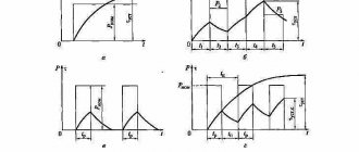
Starting the motor with a star-delta circuit
When directly starting powerful three-phase electric motors using a reverse control circuit, voltage drops occur in the network. This is due to the large inrush currents flowing at this moment. To reduce the current value, use a gradual start of the motor according to the star-delta circuit.
READ Swap gas 3110 from 402 to 406 how to connect the starter relay
The bottom line is that the beginning and end of each stator winding are led out into a terminal box. The circuit is controlled by three contactors. They gradually turn on the windings in a star, and then, when the engine accelerates, they bring the system to operating condition when connected in a delta.
Option 3: changing the starting winding to the working winding, and vice versa
It is possible to organize the reverse of a single-phase 220V motor using the methods described above only if taps from both windings with all beginnings and ends come out of the housing: A, B, C and D. But there are often motors in which the manufacturer intentionally left them outside only 3 contacts. In this way, he protected the device from various “homemade products”. But still there is a way out.
The figure above shows a diagram of such a “problematic” motor. It only has three wires coming out of the housing. They are marked with brown, blue and purple colors. The green and red lines corresponding to the end B of the starting winding and the beginning C of the working winding are interconnected internally. We will not be able to access them without disassembling the engine. Therefore, it is not possible to change the rotor rotation using one of the first two options.
In this case, do this:
- Remove the capacitor from the initial terminal A;
- Connect it to the final terminal D;
- From wires A and D, as well as the phase, taps are made (you can reverse it using a key).
Look at the picture above. Now, if you connect the phase to tap D, the rotor rotates in one direction. If the phase wire is transferred to branch A, then the direction of rotation can be changed in the opposite direction. Reversing can be done by manually disconnecting and connecting the wires. Using a key will help make the job easier.
Important! The last version of the reversible connection diagram for an asynchronous single-phase motor is incorrect. It can only be used if the following conditions are met:
- The length of the starting and working windings is the same;
- Their cross-sectional area corresponds to each other;
- These wires are made of the same material.
All these quantities affect resistance. It must be constant at the windings. If suddenly the length or thickness of the wires differ from each other, then after you organize the reverse, it turns out that the resistance of the working winding will become the same as it was before for the starting winding, and vice versa. This may also cause the engine to fail to start.
Attention! Even if the length, thickness and material of the windings are the same, operation with a changed direction of rotation of the rotor should not be prolonged. This can lead to overheating and engine failure. The efficiency also leaves much to be desired.
How to change polarity on an electric motor
Content
- Reconnecting the working winding
- Reconnecting the starting winding
- We change the starting winding to a working one or the working winding to a starting one
If you have already connected an asynchronous electric motor according to a circuit that provides for one-way rotation, but there is a need for reverse, you are faced with the question: how to change the polarity on the electric motor? There are several ways to change the direction of rotation of the motor.
Reconnecting the working winding
To do this, you can open the case, remove and turn over the winding, then return the covers to their place. But there is a more ergonomic option in which you do not have to disassemble the unit - just reconnect the contacts that go out (this only works if 4 contacts are out). So, you are required to:
- Turn off the engine.
- Determine which pair of terminals corresponds to the beginning and end of the working winding (the second pair belongs to the starting winding and is not needed at the moment).
- Transfer the phase from the initial end of the winding to the final one, and zero - from the final end to the initial one (or vice versa).
As a result of these actions, the rotor will rotate in the opposite direction, which is what you required.
Reconnecting the starting winding
Your actions are similar to those described in the previous version, only the beginning and end of the starting winding change places. This can also be done without opening the case. First, find out which pair of wires corresponds to the beginning and end of the starting winding. Then connect the beginning of the working winding to the beginning of the starting winding (which was previously connected to the start-charging capacitor), and connect the capacitance to the end of the starting winding.
Thus, the beginning and end of the starting winding are swapped, which changes the direction of rotation of the motor.
We change the starting winding to a working one or the working winding to a starting one
In many motor models, only 3 terminals go outside. This is done in order to protect the unit from damage caused by interference with its operation. But even in this case, you can make the engine rotate in the other direction, subject to the following conditions:
- The length and cross-sectional area of the working and starting windings must be the same.
- The wires are made of the same material.
These data influence the resistance, which must remain constant. When changing polarity, if the length or cross-sectional area of the wires do not match, the resistance of the starting winding will become the same as that of the working one (or vice versa). This will prevent the engine from starting.
Keep in mind that the efficiency of the electric motor will decrease, and its operation in operating mode should be short-lived, otherwise overheating of the unit with subsequent failure is inevitable.
To reverse without disassembling the device, you need to:
- Remove the capacitor from the initial terminal of the starting winding.
- Connect it to the final terminal of the working winding.
- Let out layers from both of these terminals and phases.
With this scheme, to rotate the motor in one direction (for example, clockwise), a phase should be connected to the tap of the end of the working winding. To rotate the rotor in the opposite direction, you need to transfer the phase wire to the tap of the beginning of the starting winding. You can connect and disconnect wires manually, but it is better to use a key.
If a long operating period of the motor is planned, this method should not be used. Open the motor housing and reconnect in the manner described in the first or second paragraphs. In this case, the efficiency of the unit will not decrease.
All these manipulations can be avoided if initially, when connecting the electric motor, the possibility of reversing is provided and a push-button switching station is installed.
Why is engine reverse needed?
Many mechanical actions in household and industrial devices are carried out using an asynchronous engine. In connection with this, there is often a need to change the direction of movement, based on the tasks being performed. Sometimes the reverse function for a mechanism is permanent, and sometimes it is temporary.
- The first type includes all lifting mechanisms, cranes, electric drives of shut-off and control devices and actuators operating in the “open/close” mode.
- Another type of reverse includes mechanisms in which this function is used very rarely, usually in emergency situations: conveyors, escalators, pumping units.
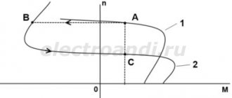
The reverse function in an electric motor is sometimes used for braking, since when it is disconnected from the electrical network, the rotor, having significant inertia, continues to operate. Such a short-term start of reverse causes the engine to slow down. This method is also called counter-inclusion.
How to implement a reverse circuit?
To change the direction of rotation of the rotor, you need to swap 2 of the 3 phases of its winding. Then the electromagnetic field of the stator changes its direction of movement, while the rotor, in the initial period of time, moving by inertia, will begin to slow down until it finally stops. And only then will it spin in a different direction.
Replacing the polarity of the electric starting winding can be done with a control toggle switch according to the diagram. It can be selected with 2 or 3 fixed positions and 6 outputs. You need to select such a device based on the current load and permitted voltage.
It is preferable to pass current to the toggle switch from the auxiliary winding, which operates for a short time. The above will make it possible to significantly increase the working resource of the contact group.
Reversing an asynchronous motor with capacitor starting is best done according to the following scheme:
- During a difficult start, an additional capacitor is connected in parallel to the main capacitor, using the middle contact with a self-resetting NVD.
- In this example, the reverse toggle switch is switched only when the rotor is locked, and not when it is rotating.
- A random change in the direction of operation of a motor under voltage is associated with huge current surges, which depletes its motor resource. For this reason, the location of the reverse toggle switch on the equipment must be selected in such a way as to make it impossible to accidentally turn it on during operation. It is better to install it in some recessed place in the structure.
If the motor does not operate properly after assembling the circuit, you will need to double check that the wires are going to the correct switch terminals. And also make sure that the wiring is not loose or damaged.
It is recommended to use a magnifying glass to ensure that the connections are made correctly and that even the thinnest strand of wire does not accidentally touch another wire or terminal.
How to change the direction of rotation of a single-phase asynchronous motor
Rice. 1 Motor connection diagram for a single-phase asynchronous motor with a starting capacitor.
Let's take as a basis an already connected single-phase asynchronous motor with a clockwise rotation direction (Fig. 1).
- points A, B conventionally indicate the beginning and end of the starting winding; for clarity, brown and green wires are connected to these points, respectively.
- Points C and B conventionally indicate the beginning and end of the working winding; for clarity, red and blue wires are connected to these points, respectively.
- arrows indicate the direction of rotation of the rotor of an asynchronous motor
Task.
Change the direction of rotation of the single-phase asynchronous motor in the other direction - counterclockwise.
To do this, it is enough to reconnect one of the windings of a single-phase asynchronous motor - either working or starting. Option No. 1
We change the direction of rotation of a single-phase asynchronous motor by reconnecting the working winding.
Fig.2 With this connection of the working winding, relative to Fig.
1, single phase induction motor will rotate in the opposite direction. Option No. 2
We change the direction of rotation of a single-phase asynchronous motor by reconnecting the starting winding.
Fig.3 With this connection of the starting winding, relative to Fig.
1, single phase induction motor will rotate in the opposite direction. Important note.
This method of changing the direction of rotation of a single-phase asynchronous motor is possible only if the motor has separate taps of the starting and operating windings.
Fig.4 With this connection of the motor windings, reverse is impossible.
In Fig. Figure 4 shows a fairly common version of a single-phase asynchronous motor, in which the ends of windings B and C, the green and red wires, respectively, are connected inside the housing. Such a motor has three terminals, instead of four as in Fig. 4 brown, purple, blue wire.
UPD 09/03/2014 Finally, I was able to test in practice a not very correct, but still used method of changing the direction of rotation of an asynchronous motor. For a single-phase asynchronous motor, which has only three terminals, it is possible to make the rotor rotate in the opposite direction by simply swapping the run and start windings. The principle of such inclusion is shown in Fig. 5
Rice. Non-standard reverse of an asynchronous motor
Where you should definitely start connecting the engine: 2 important time-tested points
Before turning on any electric motor for the first time, it is necessary to clarify its structure: the design of the stator and rotor, the condition of the bearings.
From my own and other people’s experience, I can assure you that it is easier to loosen a few nuts, inspect the internal structure, identify defects at the initial stage and eliminate them, than to deal with complex repairs that could have been prevented after starting a short operation.
Important Warning
Novice electricians quite often create engine malfunctions themselves, violating the technology for disassembling it, working with an ordinary hammer: they break the edges of the shaft.
To preserve the structure of parts without damaging them, it is necessary to use a special electric motor bearing puller.
In the most extreme case, when it is not available, blows with a hammer are applied through thick plates of soft metal (copper, aluminum) or dense dry wood (apple tree, pear tree, oak).
How bearing condition affects engine performance
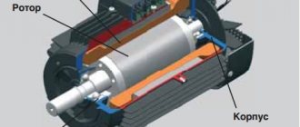
Any asynchronous electric motor (IM) has a rotor with squirrel-cage windings. A current is induced in them, creating a magnetic flux that interacts with the rotating magnetic field of the stator, which is its source of movement.
The rotor inside the housing is mounted on bearings. Their condition greatly affects the quality of rotation. They are designed to ensure easy sliding of the shaft without backlash or runout. Any violations are unacceptable.
The fact is that the stator winding can be considered as an ordinary electromagnet. If the rotor's bearings are broken, then under the influence of the magnetic field it will begin to be attracted, approaching the stator winding.
The gap between the rotating and stationary parts is very small. Therefore, touching or beating the rotor can touch, scratch, or deform the stator windings, irreversibly damaging them. The repair will require a complete rewinding of the stator, and this is a very difficult job.
Be sure to disassemble the electric motor before connecting it, and carefully inspect its entire internal structure.
What should be taken into account in the design of stator windings and how to prepare them
The home mechanic most often comes across electric motors that have already been used somewhere, and, perhaps, have undergone reconstruction or rewinding. Nobody usually declares this, the information on nameplates and tags is not changed, it is left the same. Therefore, I recommend visually inspecting their insides.
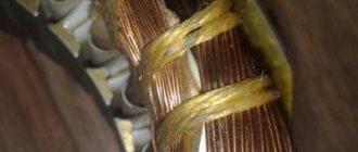
Stator coils for asynchronous motors for power supply from single-phase and three-phase networks differ in the number of windings and design.
A three-phase electric motor has three absolutely identical windings, spaced apart in the direction of rotation of the rotor by 120 angular degrees. They are made of one wire with the same number of turns.
They all have equal active and inductive resistance and occupy the same number of slots inside the stator.
This allows you to initially assess their condition with a conventional digital multimeter in ohmmeter mode with the voltage turned off.
A single-phase induction motor has two different windings on the stator, separated by 90 angular degrees. One of them is designed for long-term passage of current in the nominal operating mode and is therefore called the main, main or working.
To reduce heating, it is made with a thicker wire that has lower electrical resistance.
A second winding of greater resistance and smaller diameter is mounted perpendicular to it, which makes it possible to distinguish it visually. It is designed for short-term flow of starting currents and turns off immediately when the rotor reaches the rated speed.
The starting or auxiliary winding occupies approximately 1/3 of the stator slots, and the rest is allocated to the working turns.
However, this rule has exceptions: in practice, there are single-phase electric motors with two identical windings.
To connect the stator to the power supply, the ends of the windings are brought out with wires. Taking into account the fact that one winding has two ends, a three-phase electric motor can, as a rule, have six terminals, and a single-phase motor can have four.
But there are exceptions to this simple rule related to internal switching of pins to simplify installation on special equipment:
- for three-phase motors the following can be output from the stator:
- three cores for internal delta circuit assembly;
- or four - for a star;
- a single-phase electric motor can have:
- three outputs with internal combination of one end of the starting and working windings;
- or six ends for a design with a starting winding and a built-in contact for disconnecting it from the centrifugal regulator.
Technical condition of winding insulation
Where and under what conditions the stator was stored is not always known. If it was unprotected from precipitation or inside wet rooms, then its insulation requires drying.
At home, the disassembled stator can be placed in a dry room to dry. It is possible to speed up the process by blowing a fan or heating with conventional incandescent lamps.
Make sure that the heated glass of the lamp does not touch the winding wire; ensure an air gap. The end of the drying process is associated with the restoration of the insulation properties. This process must be controlled by measurements with a megohmmeter.
How to Change the Direction of Rotation of a 220V Motor
For a reversible single-phase asynchronous motor
Before choosing a wiring diagram for a single-phase induction motor, it is important to find out whether it needs to be reversed. the direction of rotation for this job , then purposefully organize the opposite using a pusher. If one-way rotation is enough for you, then the most common non-switching scheme is suitable. But what if, after connecting to it, you decide you still need to change direction?
Formulation of the problem
Imagine that for an asynchronous single-phase motor, which is already associated with starting power, the shaft rotation initially occurs clockwise, as shown in the figure below.
Let's clarify the main points:
- Point A indicates the beginning of the initial winding, and point B indicates its end. Source A is connected to the coffee wire and Green is connected to the terminal.
- Point C indicates the beginning of the winding and point D indicates the end. The red wire is connected to the output pin and the blue wire is connected to the output pin.
- The direction of rotation of the rotor is indicated by arrows.
We set ourselves the task of spinning a single-phase motor without opening its housing to allow the rotor to spin in a different direction (in this example, counterclockwise). This can be solved in three ways. Let's take a closer look at them.
Option 1: Connect a snare
So changing the direction of rotation of the motor allows you to swap only the beginning and end of the working (unchanged) winding, as shown in the figure. You may think that to do this you will have to open the case, remove the winding and turn it. You don't need this, because to work with contacts externally:
- Four wires should come out of the housing. 2 of them correspond to the beginning of the working and starting windings, and 2 to their ends. Determine which pair relates only to the working winding.
- You will see that two strips are connected to this pair: phase and zero. When the motor is turned off, rotate the phase shift method from the initial winding contact to the end and from zero to the end. Or vice versa.
Design and connection of single-phase electric motors 220V
Single-phase 220V electric motors are widely used in a variety of household and industrial devices: refrigerators, washing machines, pumps, drills, sharpening and similar processing machines. Their technical characteristics are somewhat inferior to those of three-phase motors. There are two most common types of single-phase electric motors for power frequency AC power:
- asynchronous;
- collector
The former are simpler in design, but have a number of disadvantages, the main of which are difficulties in changing the direction and speed of rotation of the rotor.
Next, single-phase asynchronous electric motors and commutator AC motors are considered.
Single-phase asynchronous electric motors
Device and principle of operation
The power of such a single-phase 220V motor can, depending on the design, range from 5 W to 10 kW. Its rotor is usually a short-circuited winding (“squirrel cage”) - copper or aluminum rods closed at the ends.
Such a single-phase motor usually has two windings offset by 90° relative to each other. The working (main) one occupies most of the stator slots, and the starting (auxiliary) one occupies the remaining part. And it is called single-phase because it has only one working winding.
Alternating current flowing through the main winding creates a periodically changing magnetic field. It can be considered to consist of two circular ones with the same amplitude, rotating towards each other.
According to the law of electromagnetic induction, in closed turns of the rotor, a changing magnetic flux creates an induced current that interacts with the field that generates it. If the rotor is stationary, the moments of the forces acting on it are the same, as a result of which the rotor remains stationary.
If the rotor begins to rotate, then the equality of the moments of these forces will be violated, since the sliding of its turns relative to the rotating magnetic fields will become different. As a consequence, the Ampere force acting on the rotor turns from the direct magnetic field will be significantly greater than from the reverse one.
An induced current in the rotor turns can only arise when they cross the magnetic field lines. And to do this, they must rotate at a speed slightly lower than the field rotation frequency (with one pair of poles - 3000 rpm). Hence the name that such electric motors received, asynchronous.
Subscribe to the newsletter
In order for mechanisms in production or at home, be it wood or metalworking machines, a cantilever pump, a conveyor belt, a crane beam, a sharpening machine, an electric lawn mower, a feed chopper or another device to work without breakdowns, it is necessary, first of all, for the electric motor shaft to rotate in the right direction.
In order to avoid mistakes and prevent rotation of the mechanism shaft in the opposite direction, in accordance with paragraph 2.5.3 of the “Rules for the technical operation of consumer electrical installations,” arrows in the direction of rotation of the electric motor .
Motor shaft rotation direction
The direction of rotation of the electric motor is determined from the single end of the shaft. If the engine has two shaft ends, then rotation is determined from the side of the shaft, which has a larger diameter. According to GOST 26772-85, the right direction corresponds to clockwise shaft movement. For the most common three-phase motors with a squirrel-cage rotor, the shaft will rotate to the right if the sequence of phases through which voltage is supplied to the ends of the stator windings corresponds to the alphabetical sequence of their markings - U1, V1, W1.
Right hand rotation
For single-phase motors with a squirrel-cage rotor, the shaft will rotate clockwise when the phase is supplied to the end of the working winding.
Changing the direction of shaft rotation in three-phase electric motors
The operation of some mechanisms requires left-hand rotation of the shaft. Knowing how to change the direction of rotation of an electric motor , this can be done without any modification or alteration of the drive motor itself. To change the direction of movement you need:
- de-energize the electric motor;
- remove the terminal box cover;
- rearrange the cores of the power cable in accordance with the diagram shown in Fig. 3: reconnect the black insulated wire (L3) to pin V1 in the terminal box, and reconnect the brown wire (L2) to pin W1.
Left-hand rotation
If the operation of the engine requires constant switching of the engine from right-hand rotation to left-hand rotation, its connection is carried out according to a special circuit,
Reversing a single-phase electric motor
You can start the rotation of a single-phase asynchronous electric motor by reconnecting the phase to the beginning of the working winding.
Knowing how to change the direction of rotation of an electric motor, you can connect a single-phase electric motor with the ability to switch from right-hand rotation to left-hand rotation using a three-pin switch.
DIY reversible connection of a single-phase asynchronous motor
Before choosing a connection diagram for a single-phase asynchronous motor, it is important to find out whether to reverse it. If for real work you will often need to change the direction of rotation of the rotor, then it is advisable to organize reversal with the introduction of a push-button station. If one-sided rotation is enough for you, then the most common scheme without the ability to switch will do. But what should you do if, after connecting via it, you decide that the direction still needs to be changed?
Tags
The direction of rotation of the electric motor is the tolerance of the rotation of the shaft. The direction of rotation of the shaft is the direction of rotation of the electric motor. The direction of rotation of the shaft is the direction of rotation that rotation is determined by the rotor rotation of the shaft. Right-hand rotation of the rotation of the electric motor. the electric motor shaft rotated. the rotation of the electric motor. the electric motor shaft of the electric motor connecting the electric motor through a single-phase electric motor. Direction of rotation arrows of the direction of rotation Direction of rotation Determining the direction of rotation the right direction corresponds to Changing the direction of rotation
winding the body must do another one read parts acceleration
Formulation of the problem
Let's imagine that an asynchronous single-phase motor, already connected with the introduction of a starting-charging capacity, initially has a shaft rotation oriented clockwise, as in the picture below.
Let's clarify the fundamental points:
- Point A marks the beginning of the starting winding, and point B marks its end. A coffee colored wire is connected to the initial terminal A, and a greenish colored wire is connected to the final terminal.
- Point C marks the beginning of the working winding, and point D marks its end. A reddish wire is connected to the initial contact, and a blue wire is connected to the final one.
- The direction of rotation of the rotor is indicated by arrows.
Option 1: reconnecting the working winding
To change the direction of rotation of the motor, you can only swap the beginning and end of the working (constantly turned on) winding, as shown in the figure. You might think that to do this you will have to open the case, take out the winding and twist it. There is no need to do this, since it is enough to work with the contacts from the outside:
- There should be four wires coming out of the housing. 2 of them correspond to the beginnings of the working and starting windings, and 2 to their ends. Determine which pair belongs only to the working winding.
- You will see that two strips are connected to this pair: phase and zero. With the motor turned off, reverse the phase by switching the phase from the initial winding contact to the final one, and zero - from the final to the initial one. Or the opposite.
As a result, we get a diagram where points C and D change places with each other. Now the rotor of the asynchronous motor will spin in the other direction.
HOW TO CHANGE THE DIRECTION OF SHAFT ROTATION IN A SINGLE-PHASE MOTOR
The motor was taken from a household meat grinder. Direction
We were not happy with the movement, we had to change it. All the information.
How to change the direction of rotation of a three-phase asynchronous motor?
Let's figure out how easy it is to change the direction of rotation
three-phase
motor
to the opposite.
Option 2: reconnecting the starting winding
The second way to organize the reverse of a 220 Volt asynchronous motor is to swap the beginning and end of the starting winding. This is done by analogy with the first option:
- Of the four wires coming out of the motor box, find out which of them correspond to the starter winding taps.
- Initially, end B of the starting winding was connected to the beginning C of the working winding, and beginning A was connected to the starting-charging capacitor. You can reverse a single-phase motor by connecting the capacitance to terminal B, and the beginning of C to the beginning of A.
After the actions described above, we get a diagram as in the figure above: points A and B have swapped places, which means the rotor began to turn in the opposite direction.