The CNC servo motor is an electric motor with position feedback. It receives a control signal, by which it changes the position of the rotor by a given amount, monitors this change and controls the power parameters. The presence of feedback is the main difference between servomotors and stepper motors, which use a step counting system to determine movements.
- electric motor;
- rotor position sensor (Hall sensors or encoders are most often used in CNC machine drives);
- control signal converter;
- power supply (inverter or frequency converter).
The operating principle of a servomotor with the simplest control circuit is based on comparing the specified movement with the readings of a feedback sensor. Voltage is supplied to the windings through a relay. CNC motion drives use more complex control circuits based on logic controllers. They have a number of advantages that are important for the operation of the machine:
- the ability to select power in accordance with the tasks;
- automatic compensation of backlashes, gaps associated with wear, seasonal and operating temperature deformations;
- instant detection of failure - jamming, failure of electronic components;
- high travel speeds not available for stepper motors.
Expert opinion
Viktor Pavlovich Strebizh, lighting and electrical expert
Any questions ask me, I will help!
- do not overload the drum with things; if you don’t have enough space, ask for models with a maximum load of laundry of 7-8.5 kg or 9-10 kg. If there is something you don’t understand, write to me!
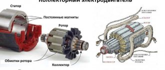
Brush and brushless servo motor designs
We propose to consider the main differences in the design of a brushed and brushless servomotor in order to understand their advantages and disadvantages. Both are electric motors consisting of a rotor (rotating part) and a stator (stationary part). The source of energy for them is electricity supplied from the machine transformer.
Brush electric motor
The commutator-brush assembly is responsible for switching the polarity of the windings. It consists of two elements:
The collector is a conductive ring divided into segments by insulators. Most often made of copper wire. The rotors of most brushed motors have several pairs of coils wound, each of them connected to “its own” segments on the ring. Brushes are conductors to which mains power is supplied.
The brushes are fixedly mounted on the stator and pressed by springs to the commutator. Switching (switching of windings) is performed when the rotor is turned: the brushes sequentially come into contact with the commutator segments.
What kind of lighting do you prefer?
Built-in Chandelier
The main advantage of a brushed motor is ease of control. There is no need to create complex electronic systems for them. The motor has a relatively low cost and with regular maintenance it operates reliably.
Brushless electric motor
Speed control is implemented on the basis of an electronic speed controller. Unlike brushed motors, where a conventional resistor is used to limit the speed, converting excess power into heat, there is no heating.
A servo drive based on a brushless motor has its disadvantages:
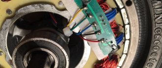
Most brushless motors have a three-phase power supply and three position sensors (one per phase).
Motor for quadcopter: how to choose, what is the difference and where to order
Good day, dear reader. Today we’ll talk about what will take your aircraft to new heights... or at least some. We will talk about electric motors. I will tell you about how to choose an engine for the quadcopter of your dreams, and many other nuances related to this topic. Go!
Brushed vs brushless
The first thing you will encounter when choosing will be these two terms. These are two different engine implementations. The main difference is the location of the winding.
Spontaneous educational program: The stator is a stationary (static) part of the engine.
Rotor is the rotating part.
Collector
Has a brush-collector unit. The commutator is a set of contacts (windings) located on the rotor, and the brush is a sliding contact located on the stator.
It is the presence of this brush that reduces the resource of the commutator motor, because it creates friction. The motor begins to rotate when DC current is supplied to it, and the direction of rotation depends on its polarity.
Smoothly accelerate and decelerate.
Advantages
- Small weight and size
- Low cost
- Easy to repair
Flaws
- Low efficiency
- Low rotation speed
- Overheat
- Rapid wear
Brushless (brushless type)
It consists of a rotor with permanent magnets and a stator with windings. Changing the direction of rotation is carried out by changing the polarity (you need to change two of the three wires). Acceleration and deceleration occur very quickly (with a jerk). They have different numbers of poles. The more of them, the slower, but with greater effort, the rotor rotates.
Advantages
- High rotation speed
- Wear resistance
- Protection from external influences
Flaws
There is a nuance here. The design of a brushless motor may vary.
- Inrunner - Standard. A rotor with permanent magnets rotates in a stator with windings.
- Outrunner – Non-standard. Here the rotor is a housing that rotates around a stator with windings.
Power (consumption)
Measured in watts. The more power, the faster the battery will run out. It's simple here
Weight
The more weight, the more powerful and slower (usually). It is important to remember that the weight of the engine itself must be taken into account when calculating the weight it must lift.
Energy efficiency (efficiency)
A complex concept that also depends on the battery, controller, propeller, and even wires. I won’t go into detail here; the higher, the better. An engine with an efficiency of 70% spends 70% of the energy consumed on flight, and 30% on heating the environment and approaching the thermal death of the universe. For brushless, the norm is 90%, and for brushed, 70%.
Heating temperature in operation
As you already understand, it directly depends on the efficiency. The more it heats up, the more energy it wastes.
Balancing and vibration level
Essentially, it's the quality of the workmanship. There is such a thing as permission. These are the limits within which deviation from the ideal is not considered a problem. The higher the manufacturing accuracy, the more coaxial the system will be, and the less vibration there will be. Sometimes it's better not to take the cheapest one.
Vibration in the engine accelerates its wear, wear of other parts, loosens the screws and makes noise. An unpleasant phenomenon.
Traction
Thrust is also known as lifting force. This is the weight that the engine (including itself) can lift. But this does not mean that a two-kilogram quadcopter requires four motors. You need a reserve of traction, you need to take into account interference, and the banal imperfection of the engines.
The formula will be something like this.
Thrust of one motor = (copter weight * 2) / number of engines As a result, for a quadcopter weighing 1 kg you need 4 engines with a thrust of 500 grams.
KV
This is a rather complex parameter - revolutions per volt without load. That is, if we have a 1000 kv motor, then when we connect it to a current source with a voltage of 12 volts, it will produce 12,000 revolutions per minute (KV*U). However, this is all extremely theoretical.
In practice, there is the load that the propeller creates and the air resistance it creates. It follows from this that the speed will be lower, or there will be none at all, since the torque depends on the torque. The higher the CV parameter, the less force the electric motor develops.
To understand the process (rough example).
Since the electric motor works due to the change in the polarity of electromagnets with a certain frequency, kv, in fact, characterizes the frequency with which the polarity of the magnets to which the permanent magnet is attracted changes. For simplicity, we assume that the permanent magnet is on the rotor. If everything goes according to plan, then the rotor travels from one variable magnet to another, after which the polarity changes, and it moves on.
If you change the polarity too often, or increase the load, then the rotor simply will not have time to accelerate and overcome the required path, and it will begin to be pulled back, or it will not move at all. It's similar to a car wheel slipping on ice. The higher the rotation speed and weight of the car, the more it will slip and develop less force.
As a result, no one knows how much is needed, because the parameter cannot be easily determined. You can simply rely on the following numbers. A lightweight racing copter with small propellers has a KV of 2100-2500, and for heavy, multi-kilogram aircraft you need to take something in the region of 200-900 KV.
How to choose the right one
There are several basic parameters from which you will have to choose. About them below. First of all, I advise you to go to the Ecalc calculator website and familiarize yourself with the calculator. It will allow you to both select the approximate configuration of the copter and calculate the flight characteristics of the finished assembly. The calculation of motors should start with this.
Total weight and required traction
This is a planning point, and perhaps the most important characteristics. You need to clearly understand how much the quadcopter will weigh. The total weight includes everything, including propellers, wires and payload. Based on the formula for calculating thrust, to achieve good flight characteristics, your copter's engines must lift its weight multiplied by two.
Frame and propeller size
The size and configuration of the frame determines how many motors you have to install and how large a diagonal propeller you can use. Now I will not go into details of the configuration and talk about how to choose the right frame. Let me just remind you that this is a critical unit, and everything will be supported on it, including heavy, vibrating engines.
Remember three simple rules.
- It is important not to miss the size here. Propellers should not overlap. Confusion with sizes also causes problems. Welcome to the world of inches
- Frame rigidity and weight are very important. If possible, take it with a safety margin. Composite materials show you off very well (a carbon frame is the ultimate dream)
- Threads in plastic either cannot be considered threads at all, or are disposable. Look for either metal inserts, or think about how else to secure the bolts
The size of the blades determines how the drone behaves in the air. A large diagonal will give greater lift and stability, at the expense of maneuverability, and vice versa. Here you need to start from your goal. You also need to take into account that the propeller creates a load on the engine. Typically the recommended size will be listed in the specification.
Nutrition
The recommended battery can also be found in the specifications. A regular bank has a nominal voltage of 3.7V. With a series connection, the voltage is summed up, and with a parallel connection, the capacitance is summed up (aka flight time).
This means that if you see a recommended 2-3S Li-po battery (7.4-11.1V), then you will need two or three lithium-polymer batteries connected in series and the corresponding power board. In this range everything will work (of course, the less, the weaker).
You can only add identical blocks in parallel, but as much as you like.
Motor markings for quadcopters
There is really no standard. Everyone puts whatever they want on their products. Fortunately, there are generally accepted standards that most people follow.
The first letter reflects the quality of workmanship.
- The “V” series is specially designed for demanding multicopters, made from the best materials with the highest assembly precision. Typically, these are racing electric motors that rotate much faster than conventional ones.
- “X” series for mid-range aircraft and multicopter models. Good efficiency, quality and assembly at a tolerable price
- “A” series - A budget solution that will be slightly worse than the previous ones, but will still work well. Don't be afraid of her
The first four digits are the parameters of the magnetic circuit. The first two are the diameter, the second two are the thickness of the set. You don't really need them very much. Do not bother. You need to know them mainly in order to understand the next parameter.
Spontaneous educational program: The magnetic core is the part of the motor or transformer on which the winding is wound. It is made up of plates.
Number of turns
The thickness of the wire depends on the number of turns, with equal parameters of the magnetic circuit. 13 or 15 turns (for example) can be wound on the same magnetic circuit.
The more turns, the smaller the cross-sectional diameter of the wire and the higher the internal resistance. Hence, with an equal supply voltage, with a larger number of turns, the current and speed will be lower. This is confirmed by the KV parameter.
For a brushless motor with 15 turns, it will be lower than for the same motor with 13 turns.
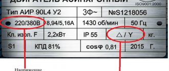
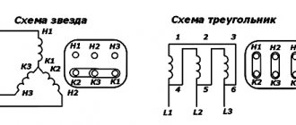
The last letter is the type of three-phase connection - star or triangle (Y/* or T/Δ, respectively). Again, I won’t load it with electronics, and in the case of quadcopters, the connection is not so important.
- A motor connected through a star will accelerate more softly and smoothly, but will not be able to develop the maximum declared power
- Connecting via a delta will give a sharper increase in speed and full declared power, but will require a much higher starting current
Let’s take the following marking A2212/15T for analysis.
22 – magnetic core with a diameter of 22mm12 – set thickness 12mm15 – 15 turnsA – Consumer goods for budget devices
T – (sometimes replaced by Δ) delta (triangle) winding
Source: https://DronGeek.ru/novichkam/vybiraem-dvigatel
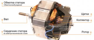
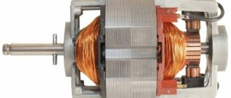
Commutator motor design
In order to understand how a commutator motor works, you need to understand its design. Regardless of the type of power unit, it consists of the following main elements:
- Anchor. It consists of a metal shaft on which windings are installed. The shaft is mounted on plain or rolling bearings in the motor housing. The armature is a moving part of the motor that transmits torque to the necessary equipment;
- Switch (collector). Necessary for determining the position of the anchor. Located on the rotor. Made in the form of copper contacts of trapezoidal cross-section;
- Brushes. Made from graphite. Brushes are used to apply voltage to the rotor windings;
- Brush holders. Made from metal or plastic. The brush holders are installed on the motor housing using non-conductive gaskets. This design eliminates the supply of voltage to the motor housing;
IMPORTANT: Brushes or holders are equipped with springs. They are necessary to press the brush against the commutator during operation of the power plant.
- Bearings. Small motors use plastic or metal bushings. The motor is equipped with two bearings. They are necessary for normal rotation of the armature shaft;
- Stator core. Made from a large number of metal plates;
- Windings Necessary to create a magnetic field.
Expert opinion
Viktor Pavlovich Strebizh, lighting and electrical expert
Any questions ask me, I will help!
The operating principle of a servomotor with the simplest control circuit is based on comparing the specified movement with the readings of a feedback sensor. If there is something you don’t understand, write to me!
Three-phase brushless DC motor
Most databases are implemented in three-phase design. To control such a drive, the controller has a DC-to-three-phase pulse converter (see Fig. 7).
Figure 7. OBD voltage diagrams
To explain how such a valve motor works, together with Figure 7, you should consider Figure 4, which shows in turn all the stages of the drive’s operation. Let's write them down:
- A positive impulse is applied to coils “A”, while a negative impulse is applied to “B”, as a result the armature moves. Sensors will record its movement and send a signal for the next switching.
- Coil “A” is turned off, and a positive pulse goes to “C” (“B” remains unchanged), then a signal is sent to the next set of pulses.
- “C” is positive, “A” is negative.
- A pair of “B” and “A” works, which receive positive and negative impulses.
- A positive pulse is re-applied to “B”, and a negative pulse to “C”.
- Coils “A” are turned on (+ is supplied) and the negative pulse on “C” is repeated. Then the cycle repeats.
In the apparent simplicity of control there are a lot of difficulties. It is necessary not only to monitor the position of the armature in order to produce the next series of pulses, but also to control the rotation speed by adjusting the current in the coils. In addition, you should select the most optimal parameters for acceleration and braking. It is also worth remembering that the controller must be equipped with a unit that allows you to control its operation. The appearance of such a multifunctional device can be seen in Figure 8.
Rice. 8. Multi-function brushless motor control controller
Operating principle of a commutator motor
A 220 Volt AC brushed motor and a DC motor convert electrical energy into physical force. The creation of physical force is carried out by unwinding the armature mounted on two bearings in the motor housing.
The rotor and stator of the power unit have windings. They are made of wire. To avoid short-circuiting of the winding turns with each other, the wire is made in an insulating sheath. Voltage is supplied to the stator winding using a wire.
The commutator motor armature is movable. A collector is used to transmit voltage to the armature winding.
It is made in the form of copper contacts. Voltage is transmitted to them through graphite brushes. This design allows voltage to be transferred to the armature winding regardless of its rotation speed.
When electric current passes through the windings, a magnetic field is created. The armature winding has a magnetic field of opposite polarity to the field of the stator winding. Under the influence of electromagnetic fields of different polarities, the motor armature begins to rotate.
ATTENTION: The brushed motor can be used as a DC generator.
Tags
Brushless motor Motor DC motor Brushless DC motor Stepper motor Electric motor
The site runs the DISQUS commenting service, which allows you to leave comments on multiple sites with just one Disqus.com account.
If you are commenting as a guest (without registering on disqus.com), pre-moderation time will be required before your comment can be published.
Which washing machine to choose
The moment of purchase has arrived. Now have a blast, because after defining the “dream engine” the entire horizon of criteria opens up. Each model has a so-called technical specifications passport (a sticker on the body and instructions). Basic information is provided there. In the article Washing machines: deciphering functions and programs, we talk in more detail about the interesting features of washing modes. We recommend reading it.
You know, an automatic washing machine simplifies household chores, regardless of which motor makes it “dance.” However, it’s great that now you choose your assistant with an understanding of her inner world and knowledge of what to expect during the period of use. We wish you only the right purchases and informed decisions!
Expert opinion
Viktor Pavlovich Strebizh, lighting and electrical expert
Any questions ask me, I will help!
The collector has a cylindrical shape and is made of copper plates, sometimes called lamellas, which are isolated from each other by mica or textolite spacers. If there is something you don’t understand, write to me!
Definition
A brushless DC motor is called a DC electric motor, the current in the windings of which is switched by a special commutator device - it is called a “driver” or “inverter” and these windings are always located on the stator. The switch consists of 6 transistors, they supply current to one or another winding, depending on the position of the rotor.
In the domestic literature, such motors are called “valve” (because semiconductor switches are called “valves”), and there is a division of such electric machines into two types according to the shape of the back-EMF. In foreign literature, this distinction is preserved; one of them is called similarly to the Russian “BLDC” (brushless direct current drive or motor), which in literal translation sounds like a “brushless direct current motor”; a trapezoidal EMF arises in their windings. Valve electric motors with sinusoidal EMF are called PMSM (Permanent magnet synchronous machine), which translates as “synchronous electric motor excited by permanent magnets.”
Bottom line
Drones are a rather complex and precise mechanism that requires a careful approach to the selection of components. I hope that after reading this article you understand a little more about the driving force of your aircraft.
And as always, a banal but very important parting word - think before you act. Even spending a lot of money on the best equipment does not guarantee that it will work well. Start from what you need. Read, learn, analyze.
If you have any questions, ask in the comments on the site. We will try to answer them. And most importantly, without which your copter will definitely not fly. Subscribe to our groups on social networks and share posts with friends (buttons for this can be found below). Good luck, pilot, see you again!
(
14 ratings, average: 3.86 out of 5)