In any technology, LEDs are used to display operating modes. The reasons are obvious - low cost, ultra-low power consumption, high reliability. Since the indicator circuits are very simple, there is no need to purchase factory-made products.
From the abundance of circuits for making a voltage indicator on LEDs with your own hands, you can choose the most optimal option. The indicator can be assembled in a couple of minutes from the most common radioelements.
All such circuits are divided into voltage indicators and current indicators according to their intended purpose.
What is a logic probe used for?
This device is successfully used when it is necessary to perform a preliminary check of the operability of the elements of a simple electrical circuit, as well as for the initial diagnosis of simple devices - that is, in cases where high measurement accuracy is not required. Using a logic probe you can:
- Determine the presence of a voltage of 12 - 400 V in the electrical circuit.
- Determine the poles in a DC circuit.
- Check the condition of transistors, diodes and other electrical elements.
- Determine the phase conductor in the AC electrical circuit.
- Ring the electrical circuit to check its integrity.
The simplest and most reliable devices with which the above manipulations are performed are an indicator screwdriver and a sonic screwdriver.
The ideal indicator for a trader
The question arises, if the EMA is already working at its limit and shows the most relevant price changes, then why do traders not use the EMA all the time? The fact is that for EMA it does not matter at all how long the trend being studied is. Any more or less significant price surge radically changes the direction of the forecast, which can be very misleading and lead to losses.
It turns out that traders do not need to have indicators with low lag - we need some balance between short reaction time and filtering out false emissions. The most famous of these developments is the adaptive moving average - AMA. There are also quite a lot of variations.
Electrician's probe: principle of operation and manufacture
A simple identifier with two LEDs and a neon light bulb, which has received the name “arcashka” among electricians, despite its simple device, allows you to effectively determine the presence of a phase, resistance in an electrical circuit, and also detect a short circuit (short circuit) in the circuit. The universal electrician's tester is mainly used for:
- Diagnostics for broken coils and relays.
- Continuity checks of motors and chokes.
- Checking rectifier diodes.
- Definitions of terminals on transformers with multiple windings.
This is not a complete list of tasks that can be solved using a probe. But the above is enough to understand how useful this device is in the work of an electrician.
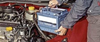
A regular battery with a voltage of 9 V is used as a power source for this device. When the tester probes are closed, the current consumption does not exceed 110 mA. If the probes are open, then the device does not consume electricity, so it does not need either a diagnostic mode switch or a power switch.
The probe is capable of performing its full functions until the voltage at the power supply drops below 4 V. After this, it can be used as a voltage indicator in circuits.
Read also: Letter designation of the fuse on the diagram
During the continuity of electrical circuits, the resistance of which is 0 - 150 Ohms, two light-emitting diodes light up - yellow and red. If the resistance value is 151 Ohm - 50 kOhm, then only the yellow diode lights up. When a network voltage of 220 V to 380 V is applied to the probes of the device, the neon lamp begins to glow, and at the same time a slight flickering of the LED elements is observed.
The diagram of this voltage indicator is available on the Internet, as well as in specialized literature. When making such a probe with your own hands, its elements are installed inside the housing, which is made of insulating material.
Often, for these purposes, the housing from the charger of any mobile phone or tablet computer is used. A probe pin should be removed from the front part of the case, and a high-quality insulated cable, the end of which is equipped with a probe or an alligator clip, should be removed from the end part.
Assembling a simple voltage tester with an LED indicator is shown in the following video:
Measuring instrument circuits
This section is devoted to the measuring and auxiliary equipment that is necessary for an amateur radio laboratory or workshop: various generators, ESR meters, auxiliary equipment necessary for a telemaster, homemade devices, and so on...
Homemade measuring instruments
Attachment to a multimeter for measuring ESR of capacitorsESR meter from a Chinese pointer instrumentSimple transistor tester (testing h21e)simple generator on OUAudio frequency generatorsActive probe for an oscilloscopeDouble-beam oscilloscope from a single-beamSimple ESR meter with a 1.5V power supplyRCL meterA device for checking battery parametersA device for measuring inductanceA device for testing capacitorsWhen boron for testing electrolytic capacitors Logic probe with a seven-segment indicator Device for determining turn-to-turn short circuits Device for testing field-effect transistors Indicator of bad contacts Capacitance meter for capacitors on an operational amplifier How to measure electromagnetic radiation with a multimeter Electric field indicator Frequency meter on an ATtiny2313 microcontroller Product length meter Substance identity meter Resonant frequency meter Oscilloscope from a TV Homemade counter GeigerRelay as a generatorSinusoidal signal generator on logic chipsLED oscilloscopeCapacitance meter and inductanceLC meter based on simple logicAmateur radio instruments for measuring inductanceGeiger counter made from a neon lampIndicator of high-frequency radiationMethodology for checking inductor or inductance for saturationPortable device for measuring resistance and capacitanceFM wave meterDetector for the presence of an audio signalTransistor probe with LED indicationLogic probe probeHigh-frequency generator (up to 15 mHz)Pulse generator triangular and rectangular shape Simple transistor audio frequency generator Device for testing transistors and diodes without desoldering LED transistor tester Universal measuring device Non-linear distortion meter Frequency meter - capacitance meter AC millivoltmeter Spark flaw detector Device for measuring soil humidity, temperature and illumination Wideband noise generator Function generator on XR2206LA borator audio frequency generatorA device for determining the parameters of a zener diodeThe simplest generator for TV repairThe simplest Ohm -meter Device for testing oxide capacitors without soldering Capacitance meter for capacitors Modification of the Ts435 avometer Probe generator for checking the radio receiving path Universal probe Light and sound probe Functional generator with electronic frequency tuning AF generator on the K174UN7 chip Tone pulse generator Capacitance meter - attachment for the DT-830B (M-830V) multimeter From battery capacity meterGenerator-probe for checking IF and AF paths Frequency meter from a radio receiver Device for testing remote controls Device for testing the functionality of quartz resonators Functional generator Logic probe without a power supply Operational amplifier tester Microvoltmeter for testing audio devices Digital voltmeter with LED indicator Periodic pulse generator LF generator based on K174UN7 Voltage indicator with automatic switching of measurement limits Phase meter G 50 Hz frequency generatorLogic probe with digital display
Schemes of industrial devices
Ts4317МTs4326 device Ts4342 device Ts4353Mastech М266F (C) circuitMastech MS2001Mastech m932Mastech MY6013 multimeterMastech MY61 multimeter circuitMastech MY62 multimeterMastech MY63 multimeterMastech MY64 multimeterMastech MY65mastech multimeter MY68Multimeter Mastech M300Multimeter Mastech M320Multimeter Mastech M3900Multimeter M830Multimeter MASTECH M-832Multimeter MASTECH M-838Multimeter MASTECH M-890Multimeter MASTECH MAS-830, 830L multimeter MASTECH MAS-838 multimeter MASTECH M 93 (93A) Multimeter DT9208A circuit and characteristics multimeter MASTECH M 9502 multimeter MASTECH MS 8220 circuit diagram multimeter MASTECH MS 8221 circuit diagram multimeter MASTECH MS 8222 circuit diagram Multimeters APPA107, APPA20 7 circuitOscilloscope OML-2MOscilloscope LO-70Teletest Laspi TT-03Generator GZ-118Oscilloscope VM556AOoscilloscope S1 -64Oscilloscope S1-49Oscilloscope S1-71Oscilloscope S1-73Oscilloscope S1-96Oscilloscope S1-103Oscilloscope S1-131Avometer (tester) Ts20. Scheme, improvements
How to make an electrician's tester with your own hands?
Some thrifty hobbyists can find many useful things in their “arsenal,” including an earphone (capsule) for the TK-67-NT telephone.
Another similar device, equipped with a metal membrane, inside which there is a pair of series-connected coils, is also suitable.
Based on such a part, a simple sound probe can be assembled.
First of all, you need to disassemble the telephone capsule and disconnect the coils from each other. This is necessary in order to free their conclusions. The elements are placed in the earphone under the sound membrane, near the coils. After assembling the electrical circuit, we will receive a completely working identifier with sound indication, which can be used, for example, to check the tracks of printed circuits for mutual bridging.
The base of such a probe is an electric generator with an inductive opposite relationship, the main parts of which are a telephone and a low-power transistor (preferably germanium). If you do not have such a transistor, then you can use another one with NPN conductivity, but in this case the polarity of the power supply should be changed. If you cannot turn on the generator, the terminals of one (any) coil must be swapped with each other.
You can increase the sound volume by choosing the frequency of the electric generator so that it is as close as possible to the resonant frequency of the earphone. To do this, the membrane and the core must be placed at an appropriate distance, changing the interval between them until the desired result is obtained. Now you know how to make a voltage indicator based on a telephone earphone.
The manufacture and use of a simple voltage probe is clearly shown in the video:
Known circuit diagrams
It is better to consolidate reading skills on well-described diagrams, which have already become classic. They contain a small number of integral elements.
Radio receiver “Ishim-003”
The device has been produced since 1984. It is a receiver of frequency and amplitude modulated radio waves in the short, medium and long ranges. Widespread among radio amateurs.
Schematic diagram of Ishim-003.
It is made according to a superheterodyne circuit with two channels (FM and AM) and a frequency converter.
The frequency-modulated channel is made of an RF amplifier, a converter, an amplifier and a frequency detector. An amplitude modulated channel consists of a UHF, an IF, an IF and an amplitude detector.
At low frequencies, amplification is produced by the general ULF. The design includes an electronic counting scale, a setting indicator and a power supply.
Vega-108 stereo
The device appeared in 1979 and is a stereophonic electric record player with an output power of 2*10 W and a sound frequency of 63-18000 Hz. The device not only works as an amplifier for external signals, but can also record to a tape recorder.
The schematic diagram of the electrophone consists of blocks:
- switching;
- regulators;
- nutrition;
- preamp;
- power amplifier module;
- speaker system.
The main part of the elemental base of the player were transistors: KT815V, KT814V, KT315G. The device's power supply includes a step-down transformer with 5 secondary windings, 2 diode bridges and a voltage stabilizer made on a KT315V transistor.
Vega-108 stereo circuit diagram.
The G-602 device is used as a pickup head. The preamplifier consists of 2 channels using transistors KT3102D, KT361E, KT315B. A switch is made of switches and electronic circuitry.
Almag-01
The Almag-01 medical device is intended for the treatment of skin diseases, gastrointestinal tract, and ENT organs. It affects the body with a pulsed electromagnetic field.
The device diagram includes:
- power cord;
- inductor coils (emitters);
- cable for connecting the emitter strip to the control unit;
- uninterruptible power supply;
- pulse current generator;
- Control block.
Scheme Almag-01.
Multimeter DT-832
A universal device for measuring various electrical quantities (voltage, resistance, current, etc.). The basis of the measuring device is the ICL1706 ADC microcontroller or its analogues.
The device includes:
- analog part;
- integrator;
- comparator;
- liquid crystal display;
- digital part with control logic.
The device is convenient to use both at home and at work.
What is an indicator screwdriver used for?
The main purpose of the indicator screwdriver is to check the presence or absence of an active phase in the electrical network.
Due to this, the process of setting up equipment, repairing electrical circuits and their installation are greatly facilitated.
Using the tool, you can determine the location of the break in the phase and neutral wires yourself, without resorting to the services of an electrician.
An indicator screwdriver ensures safety when working with electricity by detecting the presence of current in the circuit.
Read also: How to draw a three-dimensional hexagon
It is often indispensable during electrical installation, especially if work is carried out with old wiring, where the phase and neutral wires cannot be distinguished visually (aluminum wires in Khrushchev-era buildings, for example).
This tool will also be needed if you need to replace or install sockets and switches in an existing electrical network.
Interestingly, the indicator can determine the position of the switch (on or off), which allows you to install it on the correct side.
Using modern models with a display in everyday life, you can perform the simplest dialing functions of the electrical network, allowing you to find out the current voltage and its other parameters.
Still, for full-fledged work you need a normal tester.
Tester. Operating rules
When and how to use an indicator screwdriver correctly, what are the requirements for the user’s personal safety?
Before checking hidden electrical wiring, the room should be de-energized. Exposed electrical wires should only be checked with a tester; do not touch them with your hands or conductors. Do not use the device in damp rooms, check the serviceability of electrical circuits with wet hands, the current passing through the body will be felt.
There should be no cracks, crevices or other damage on the tool body. If there is even minor damage, the device must be replaced. Repairing a damaged tester is not profitable; buying a new one will cost less.
Types of indicator screwdrivers
Voltage indicators, made in the form of an ordinary screwdriver, have a general operating principle, but may differ in design, functionality and design.
They are contact and non-contact.
The indicator in various models can be either a sound signal, a small LED, or even a digital screen.
Model with neon lamp
A test screwdriver with a neon lamp is the simplest tester.
The disadvantage of this contact type tool is the fairly high voltage indication threshold - from 60V.
Used to determine the phase in an AC circuit.
Not suitable for searching for broken wires.
An indicator screwdriver of the UNO type is popular in everyday life - a single-pole voltage indicator, the operating range of which is limited to the upper mark of 500V.
Used when connecting electricity meters, fuses, switches, etc.
The principle of operation of a screwdriver with a neon light bulb is that it glows when the tip comes into contact with a current-carrying conductor.
Electricity passes through the resistance resistor and is closed to the person by the second contact located at the end.
Simply put, the lamp will light up if you touch the phase wire with the tip and touch the end contact with your finger, thereby closing the circuit.
With display
Simple indicator screwdrivers equipped with displays do not use batteries, and the presence of voltage in the phase is indicated by an icon appearing on the LCD screen.
Works by reading the electrostatic field.
Typically, these tools are compact in size and the body is made of plastic.
Universal
Inside the universal indicator screwdrivers there is a microcircuit that will expand the capabilities of the tool.
There is a slider on the case - a switch through which the operating mode is selected:
The presence of voltage is indicated by a built-in light.
The presence of voltage is indicated by a light bulb. The mode is characterized by low sensitivity
• Non-contact testing with high sensitivity
The presence of current is indicated by both a light indication and an audible signal.
This mode will allow you to find current-carrying wires even under a layer of plaster.
These multifunctional indicator screwdrivers are very easy to use and, most importantly, effective.
It should be remembered that the presence of additional elements in the device increases the cost of the tool.
In addition, batteries are used for power supply, which have to be changed frequently.
With LED
The principle of operation of an indicator with an LED does not differ from options with neon lamps.
But the good thing about this tool is that it works perfectly with electrical networks with voltages less than 60V.
The LED indicator screwdriver includes a self-contained power supply and a bipolar transistor, which makes this tool multifunctional with all its simplicity.
Allows you to determine the presence of a phase using both contact and non-contact methods, and check the integrity of wires and fuses.
Electronic indicator instruments
A modern version of the voltage indicator is an electronic screwdriver with a display, sound and light indicator.
In fact, this is a full-fledged multifunctional voltage indicator, the “little brother” of the multimeter.
The presence of electric current in the circuit is indicated by a phase indicator light and an audible buzzer.
The voltage value is displayed on the LCD screen.
This device is capable of working with DC and AC networks, which allows it to be used to test the networks of vehicles powered by batteries.
As a rule, this option is not common among professional electricians due to the high cost.
Battery operated
By using an autonomous power source, battery-powered indicators allow you to determine the presence of current in a phase using a non-contact method, check the integrity of electrical wiring, and find wires hidden under plaster.
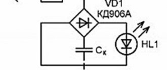
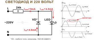
DC Voltage Check
Often there is a need to ring the low-voltage circuit of household appliances, or check the integrity of a connection, for example, a wire from headphones.
As a current limiter, you can use a low-power incandescent lamp or a 50-100 Ohm resistor. Depending on the polarity of the connection, the corresponding diode lights up. This option is suitable for circuits up to 12V. For higher voltages, you will need to increase the limiting resistor.