§79. Characteristics of asynchronous motors
Characteristics of asynchronous motors.
To properly operate an asynchronous motor, you need to know its characteristics: mechanical and operational.
Mechanical characteristics.
The dependence of the rotor speed on the load (rotating torque on the shaft) is called the mechanical characteristic of an asynchronous motor (Fig. 262, a). At rated load, the rotation speed for various motors is usually 98–92.5% of the rotation speed n1 (slip sn = 2–7.5%). The greater the load, i.e. the torque that the engine must develop, the lower the rotor speed.
As the curve in Fig. 262a, the rotation speed of an asynchronous motor decreases only slightly with increasing load in the range from zero to its highest value. Therefore, such an engine is said to have a rigid mechanical characteristic.
The engine develops the greatest torque Mmax at a certain slip skp of 10–20%. The ratio Mmax/Mnom determines the overload capacity of the motor, and the ratio Mn/Mnom determines its starting properties.
Rice. 262. Mechanical characteristics of an asynchronous motor: a - natural; b - when the starting rheostat is turned on
The engine can operate stably only if self-regulation is ensured, i.e., automatic equilibrium is established between the load torque Mvn applied to the shaft and the torque M developed by the engine. This condition corresponds to the upper part of the characteristic until Mmax is reached (to point B).
If the load torque Mvn exceeds the torque Mmax, then the engine loses stability and stops, while a current 5-7 times greater than the rated current will pass through the windings of the machine for a long time, and they can burn out.
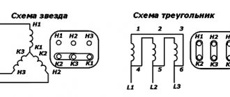
When the starting rheostat is connected to the rotor winding circuit, we obtain a family of mechanical characteristics (Fig. 262, b). Characteristic 1 when the engine is running without a starting rheostat is called natural. Characteristics 2, 3 and 4, obtained by connecting a rheostat with resistances R1п (curve 2), R2п (curve 3) and R3п (curve 4) to the motor rotor winding, are called rheostatic mechanical characteristics.
When the starting rheostat is turned on, the mechanical characteristic becomes softer (more steeply falling), since the active resistance of the rotor circuit R2 increases and skp increases. This reduces the starting current. The starting torque Mn also depends on R2. You can select the rheostat resistance so that the starting torque Mn is equal to the largest Mmax.
In an engine with increased starting torque, the natural mechanical characteristic approaches in its form the characteristic of an engine with the starting rheostat turned on. The torque of a double squirrel cage motor is equal to the sum of the two torques created by the working and starting cages.
Therefore, characteristic 1 (Fig. 263) can be obtained by summing characteristics 2 and 3 created by these cells. The starting torque Mn of such a motor is significantly greater than the torque M'n of a conventional squirrel-cage motor. The mechanical performance of the deep slot motor is the same as that of the double squirrel cage motor.
Rice. 263. Mechanical characteristics of an asynchronous motor with increased starting torque (with a double squirrel cage)
Performance characteristics.
The operating characteristics of an asynchronous motor are the dependences of the rotation speed n (or slip s), torque on the shaft M2, stator current I1, efficiency η and cosφ1, on the useful power P2 = Pmx at rated values of voltage U1 and frequency f1 (Fig. 264).
Rice. 264. Performance characteristics of an asynchronous motor
They are built only for the zone of practical stable operation of the engine, i.e. from a slip equal to zero to a slip exceeding the nominal by 10-20%. The rotational speed n changes little with increasing power output P2, just as in the mechanical characteristic; the torque on the shaft M2 is proportional to the power P2, it is less than the electromagnetic moment M by the value of the braking torque Mtr created by friction forces.
The stator current I1 increases with increasing power output, but at P2 = 0 there is some no-load current I0. The efficiency varies in approximately the same way as in a transformer, maintaining a fairly large value over a relatively wide load range.
The highest efficiency value for medium and high power asynchronous motors is 0.75-0.95 (high power machines have a correspondingly higher efficiency). The power factor cosφ1 of asynchronous motors of medium and high power at full load is 0.7–0.9.
Consequently, they load power plants and networks with significant reactive currents (from 70 to 40% of the rated current), which is a significant disadvantage of these motors.
At loads of 25–50% of the nominal load, which are often encountered during the operation of various mechanisms, the power factor decreases to values that are unsatisfactory from an energy point of view (0.5–0.75).
When the load is removed from the engine, the power factor decreases to values of 0.25-0.3, so asynchronous motors should not be allowed to operate at idle and at significant underloads.
Operation at low voltage and failure of one of the phases.
Reducing the network voltage does not have a significant effect on the rotor speed of an asynchronous motor. However, in this case, the maximum torque that an asynchronous motor can develop is greatly reduced (when the voltage decreases by 30%, it decreases by approximately 2 times). Therefore, if the voltage drops significantly, the motor may stop, and if the voltage is low, it may not start working.
On e. p.s. alternating current, when the voltage in the contact network decreases, the voltage in the three-phase network, from which the asynchronous motors driving the rotation of auxiliary machines (fans, compressors, pumps), also decreases accordingly.
In order to ensure normal operation of asynchronous motors at reduced voltage (they must operate normally when the voltage is reduced to 0.75 Unom), the power of all auxiliary machine motors is at . p.s. is taken approximately 1.5-1.6 times greater than is necessary to drive them at rated voltage.
Such a power reserve is also necessary due to some asymmetry of the phase voltages, since at the e.g. p.s. asynchronous motors are powered not from a three-phase generator, but from a phase splitter.
If the voltages are unbalanced, the phase currents of the motor will be unequal and the phase shift between them will not be equal to 120°. As a result, more current will flow through one of the phases, causing increased heating of the windings of this phase. This forces the engine to limit its load compared to operating it at symmetrical voltage.
In addition, with voltage asymmetry, not a circular, but an elliptical rotating magnetic field arises and the shape of the mechanical characteristics of the engine changes somewhat. At the same time, its maximum and starting moments are reduced.
Voltage asymmetry is characterized by an asymmetry coefficient, which is equal to the average relative (in percent) deviation of voltages in individual phases from the average (symmetrical) voltage. A three-phase voltage system is considered to be practically symmetrical if this coefficient is less than 5%.
If one of the phases breaks, the engine continues to operate, but increased currents will flow through the undamaged phases, causing increased heating of the windings; such a regime should not be allowed. Starting a motor with a broken phase is impossible, since this does not create a rotating magnetic field, as a result of which the motor rotor will not rotate.
The use of asynchronous motors to drive auxiliary machines. p.s. provides significant advantages over DC motors. When the voltage in the contact network decreases, the rotation speed of asynchronous motors, and therefore the supply of compressors, fans, and pumps, practically does not change. In DC motors, the rotation speed is proportional to the supply voltage, so the supply of these machines is significantly reduced.
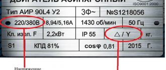
Rated values of operating power and current of electric motors
Component classes: 1.6.1.1.1. Modular circuit breakers (VAM, MSV), 1.6.5.1. Modular contactors, 1.6.1.2.1. Automatic motors (motor protection circuit breakers, MPCB), 1.6.1.3.1. Molded Case Circuit Breakers (MCCB), 1.6.5.2. Contactors, 1.6.5.3. Starters, 1.6.5.4. Overload relays and accessories, 1.12. Electric motors and drive technology
The current values given below are for standard three-phase, four-pole, short-circuit induction motors (1500 rpm at 50 Hz, 1800 rpm at 60 Hz). These values are provided as a guide and may vary depending on the motor manufacturer and number of poles.
| Motor power | Motor rated current: standard values shown in blue (according to IEC 60947-4-1 annex G) | |||||||||
| 220V | 230V | 240V | 380V | 400V | 415V | 440V | 500V | 660V | 690V | |
| 0.06 kW | 0,37 | 0,35 | 0,34 | 0,21 | 0,2 | 0,19 | 0,18 | 0,16 | 0,13 | 0,12 |
| 0.09 kW | 0,54 | 0,52 | 0,5 | 0,32 | 0,3 | 0,29 | 0,26 | 0,24 | 0,18 | 0,17 |
| 0.12 kW | 0,73 | 0,7 | 0,67 | 0,46 | 0,44 | 0,42 | 0,39 | 0,32 | 0,24 | 0,23 |
| 0.18 kW | 1 | 1 | 1 | 0,63 | 0,6 | 0,58 | 0,53 | 0,48 | 0,37 | 0,35 |
| 0.25 kW | 1,6 | 1,5 | 1,4 | 0,9 | 0,85 | 0,82 | 0,74 | 0,68 | 0,51 | 0,49 |
| 0.37 kW | 2 | 1,9 | 1,8 | 1,2 | 1,1 | 1,1 | 1 | 0,88 | 0,67 | 0,64 |
| 0.55 kW | 2,7 | 2,6 | 2,5 | 1,6 | 1,5 | 1,4 | 1,3 | 1,2 | 0,91 | 0,87 |
| 0.75 kW | 3,5 | 3,3 | 3,2 | 2 | 1,9 | 1,8 | 1,7 | 1,5 | 1,15 | 1,1 |
| 1.1 kW | 4,9 | 4,7 | 4,5 | 2,8 | 2,7 | 2,6 | 2,4 | 2,2 | 1,7 | 1,6 |
| 1.5 kW | 6,6 | 6,3 | 6 | 3,8 | 3,6 | 3,5 | 3,2 | 2,9 | 2,2 | 2,1 |
| 2.2 kW | 8,9 | 8,5 | 8,1 | 5,2 | 4,9 | 4,7 | 4,3 | 3,9 | 2,9 | 2,8 |
| 3 kW | 11,8 | 11,3 | 10,8 | 6,8 | 6,5 | 6,3 | 5,7 | 5,2 | 4 | 3,8 |
| 4 kW | 15,7 | 15 | 14,4 | 8,9 | 8,5 | 8,2 | 7,4 | 6,8 | 5,1 | 4,9 |
| 5.5 kW | 20,9 | 20 | 19,2 | 12,1 | 11,5 | 11,1 | 10,1 | 9,2 | 7 | 6,7 |
| 7.5 kW | 28,2 | 27 | 25,9 | 16,3 | 15,5 | 14,9 | 13,6 | 12,4 | 9,3 | 8,9 |
| 11 kW | 39,7 | 38 | 36,4 | 23,2 | 22 | 21,2 | 19,3 | 17,6 | 13,4 | 12,8 |
| 15 kW | 53,3 | 51 | 48,9 | 30,5 | 29 | 28 | 25,4 | 23 | 17,8 | 17 |
| 18.5 kW | 63,8 | 61 | 58,5 | 36,8 | 35 | 33,7 | 30,7 | 28 | 22 | 21 |
| 22 kW | 75,3 | 72 | 69 | 43,2 | 41 | 39,5 | 35,9 | 33 | 25,1 | 24 |
| 30 kW | 100 | 96 | 92 | 57,9 | 55 | 53 | 48,2 | 44 | 33,5 | 32 |
| 37 kW | 120 | 115 | 110 | 69 | 66 | 64 | 58 | 53 | 40,8 | 39 |
| 45 kW | 146 | 140 | 134 | 84 | 80 | 77 | 70 | 64 | 49,1 | 47 |
| 55 kW | 177 | 169 | 162 | 102 | 97 | 93 | 85 | 78 | 59,6 | 57 |
| 75 kW | 240 | 230 | 220 | 139 | 132 | 127 | 116 | 106 | 81 | 77 |
| 90 kW | 291 | 278 | 266 | 168 | 160 | 154 | 140 | 128 | 97 | 93 |
| 110 kW | 355 | 340 | 326 | 205 | 195 | 188 | 171 | 156 | 118 | 113 |
| 132 kW | 418 | 400 | 383 | 242 | 230 | 222 | 202 | 184 | 140 | 134 |
| 160 kW | 509 | 487 | 467 | 295 | 280 | 270 | 245 | 224 | 169 | 162 |
| 200 kW | 637 | 609 | 584 | 368 | 350 | 337 | 307 | 280 | 212 | 203 |
| 250 kW | 782 | 748 | 717 | 453 | 430 | 414 | 377 | 344 | 261 | 250 |
| 315 kW | 983 | 940 | 901 | 568 | 540 | 520 | 473 | 432 | 327 | 313 |
| 355 kW | 1109 | 1061 | 1017 | 642 | 610 | 588 | 535 | 488 | 370 | 354 |
| 400 kW | 1255 | 1200 | 1150 | 726 | 690 | 665 | 605 | 552 | 418 | 400 |
| 500 kW | 1545 | 1478 | 1416 | 895 | 850 | 819 | 745 | 680 | 515 | 493 |
| 560 kW | 1727 | 1652 | 1583 | 1000 | 950 | 916 | 832 | 760 | 576 | 551 |
| 630 kW | 1928 | 1844 | 1767 | 1116 | 1060 | 1022 | 929 | 848 | 643 | 615 |
| 710 kW | 2164 | 2070 | 1984 | 1253 | 1190 | 1147 | 1043 | 952 | 721 | 690 |
| 800 kW | 2446 | 2340 | 2243 | 1417 | 1346 | 1297 | 1179 | 1076 | 815 | 780 |
| 900 kW | 2760 | 2640 | 2530 | 1598 | 1518 | 1463 | 1330 | 1214 | 920 | 880 |
| 1000 kW | 3042 | 2910 | 2789 | 1761 | 1673 | 1613 | 1466 | 1339 | 1014 | 970 |
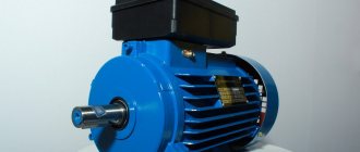
Types of electric motors
The most common is the three-phase asynchronous electric motor. DC and synchronous electric motors are rarely used.
Most electrified machines require a drive with a power of 0.1 to 10 kW, a much smaller part requires a drive with a power of several tens of kW. As a rule, squirrel-cage three-phase electric motors are used to drive working machines. Compared to a phase motor, such an electric motor has a simpler design, lower cost, greater operational reliability and ease of maintenance, slightly higher performance indicators (power factor and efficiency), and requires simple equipment for automatic control. The disadvantage of squirrel-cage electric motors is the relatively high starting current. When the power of the transformer substation and the electric motor are commensurate, its start-up is accompanied by a noticeable decrease in the network voltage, which complicates both the start-up of the motor itself and the operation of neighboring pantographs.
Along with three-phase asynchronous squirrel-cage electric motors of the basic design, separate modifications of these motors are also used: with increased slip, multi-speed, with a wound rotor, with a massive rotor, etc. Electric motors with a wound rotor are also used in cases where the power of the supply network is insufficient for starting motor with a squirrel-cage rotor.
The mechanical characteristics of asynchronous electric motors with a squirrel-cage rotor largely depend on the shape and size of the rotor slots, as well as on the method of making the rotor winding. According to these signs
Rice. 1. Torque curves M = f(S) of asynchronous electric motors
There are electric motors with a normal rotor (normal squirrel cage), with a deep groove and with two cages on the rotor. The rotor design of general-purpose squirrel-cage asynchronous electric motors with a power of over 500 W predetermines the phenomenon of current displacement in the winding, which is equivalent to an increase in its active resistance. Therefore, and also due to the saturation of the magnetic paths of dissipation fluxes, such electric motors (primarily the rotor windings) have variable parameters and the analytical expressions of their mechanical characteristics become more complicated. An increase in the active resistance of the rotor during the starting period causes an increase in the initial starting torque with a slight decrease in the strength of the initial starting current (Fig. 1).