Symbols of communication means
| Antenna for receiving, transmitting, transceiving radio equipment (image in the drawings). Next to the symbol it is allowed to indicate the wave range, for example: UHF, VHF, KB, etc. |
| Stationary radio station, radio transmitter (general designation). It is allowed to indicate the type of station next to the symbol. |
| Portable radio station (general designation). It is allowed to indicate the type of station next to the symbol. |
| Radio station transportable for a trunked mobile communication network. Next to the symbol it is allowed to indicate the system standard: SmarTrunk II, MRT 1327, LTR, etc. |
| Portable radio station (general designation). It is allowed to indicate the type of station next to the symbol. |
| Portable radio station for a trunked mobile communication network. Next to the symbol it is allowed to indicate the system standard: SmarTrunk II, MRT 1327, LTR, etc. |
| Portable radiotelephone of the cellular mobile network. Next to the symbol it is allowed to indicate the system standard: NMT-450, GSM-900, DAMPS, etc. |
| Wearable (portable) radiotelephone of a low-orbit satellite communication system. Next to the symbol it is allowed to indicate the type of device and the CCC standard: Iridium, Globalstar, etc. |
| Cordless radiotelephone. Next to the symbol it is allowed to indicate the system standard: DECT, CT-2, etc. |
| Radio receiver (general designation). It is allowed to indicate the type next to the symbol. |
| Radio receiver of the personal radio call network (pager). Next to the symbol it is allowed to indicate the type and standard of the PRV network. |
| Radio receiver of the global satellite radio navigation system (GPS). |
| Stationary radio repeater (general designation). It is allowed to indicate the repeater type next to the symbol. |
| Repeater of a base station of a trunked mobile communication network (general designation). |
| Satellite communications ground station (general designation). |
| Stationary tropospheric communication station. |
| Stationary radio relay station (two half-sets). It is allowed to indicate the type of station next to the symbol. |
| Stationary radio relay station (one half-set). It is allowed to indicate the type of station next to the symbol. |
| Radio network (image on the radio communication diagram) |
| Radio network (image on a map or area plan). |
| Radio direction (image on the radio communication diagram). |
| Radio relay line (image on a map or area plan) |
| Firefighter communication and lighting vehicle. |
| Firefighter staff car. |
| A telephone without a dialer. It is allowed to specify the type |
| A telephone with a dialer for communication via a PBX (PATS, PBX, etc.). It is allowed to specify the type. |
| Field telephone set with inductor (MB systems). It is allowed to specify the type. |
| Fax machine (image in the diagrams). |
| Single-channel sound recording device (tape recorder, voice recorder) (shown in the diagrams). |
| Multi-channel sound recording device (tape recorder) (shown in the diagrams). |
| Telephone switch, hub. The type is indicated below the symbol. |
| Low frequency amplifier, intermediate (the type of amplifier is indicated under the symbol). |
| Intermediate low frequency amplifier. The type is indicated below the symbol. |
| Microphone. |
| Speakerphone terminal device. Speaker. |
| Automatic telephone exchange (GATS - city, RATS - district, SATS - rural). |
| An automatic telephone exchange (ATS) equipped with a special communication center (USC). |
| Communication node (general designation). Inside the symbol, the type of node is indicated (TsUS, TsPPS, PSO, PSCh, etc.). |
Wired communication lines (images on plans and maps):
| Direct telephone connection. |
| Telephone communication via special communication lines |
| Telephone communication over the city telephone network |
| Connecting lines for public address devices. |
| Telegraph lines. |
| Phototelegraph (fax) communication lines. |
| Signal communication lines (remote control). |
| Permanent overhead cable communication line (under the sign is the chain number, core material, core diameter, chain No. 2, steel, 4 mm). |
| Field cable line. |
| Cable line laid in the sewer (above the sign, brand, number, core diameter). |
APPENDIX 2
to the Manual
conclusions
For standard design of equipment installation plans and structural diagrams of video surveillance systems, it is necessary to use conventional graphic symbols (CGI) and alphanumeric designations of all used devices. In addition, it is necessary to show communication lines and cable routing methods in a standard way.
The main regulatory documents in the field of registration of UGO are R 071-2017, RD 25.953-90. It is also often necessary to use GOST 21.210-2014, TIA-606-B and GOST 2.710-81.
Existing standards may contradict each other and contain outdated and currently unused devices. Therefore, projects should still create a separate sheet with a table of symbols to avoid discrepancies when using the documentation.
Comment Videomax
Where can I get a ready-made UGO database for AutoCAD?
Especially for you, we have prepared a tool palette file for dynamic blocks for AutoCAD software (Autodesk company).
The UGO SOT palette includes a list of the following blocks:
- Security television system (STS) equipment
- Security television system equipment, produced by Videomax LLC
You can download the archive with the file here.
Instructions for installing the palette are inside the archive.
Note
For any questions related to this material, you can leave a comment, and we promise that the author of the article will answer you personally, or you can make a request through the specialists of the Videomax Designer Support Department.
The Videomax company provides free consultations on the design of video surveillance systems. We will find the optimal solution to the customer’s problem, recommend software options, integration and system construction, develop algorithms for system operation and automation, and calculate station equipment with a performance guarantee. You can send requests by email or contact us by toll-free number.
If the project is already ready, you can send it for audit by filling out a special form in your personal account. Authorization required.
Equipment protection degree
Sockets, like any electrical equipment, have varying levels of protection against contact of live parts with solid particles and water. This ensures safe human use in a variety of conditions.
To mark the degree of protection, a combination of two letters (IP) and two numbers is used. IP - International Protection, which translates from English as “international protection”. And the numbers characterize its level.
For example, the degree of protection IP20 according to GOST 14254-2015 can be deciphered as follows:
- first digit 2 – current-carrying parts of the product are inaccessible to objects 12.5 mm thick or fingers;
- the second digit is 0 – water may get inside the device.
The degree of protection IP23 means that fingers cannot get inside, and the angle of safe drops falling onto the body is 60 degrees.
Main types of sockets
An electrical outlet (plug socket) is a device that allows you to quickly connect and disconnect various devices from the network.
Its main elements are:
- contacts – provide connection between the electrical network and the plug;
- block - ceramic housing for contacts and fastenings of the installation box (socket box);
- body - performs a decorative and protective role.
In the general sense of the word, the product can perform other functions. For example, connecting and disconnecting telephone communications, radio, Internet and even water supply in plumbing fixtures. Consequently, there are many structural and functional varieties of this type of connection.
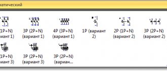
The main types of sockets used in everyday life vary:
- depending on the installation method, there are overhead and built-in;
- by the number of nests - single or a block of two, three or more;
- by the number of connections - with and without a grounding contact;
- by purpose - antenna, for telephone and Internet, for household appliances, for powerful equipment.
The device is a surface-mounted device that is simple and universal to install. It does not require making deep holes in the wall, which is convenient for temporary placement or in industrial premises. The housing together with the block is attached to the desired surface and connected to open electrical wiring.
Since the installation is not carried out in the installation box, ordinary dowel nails are suitable for reliable fastening to the plane.
The built-in installation option has a more aesthetic appearance, since the main part of the product is immersed in the wall, and only the protective casing remains outside. Thus, nothing interferes with the perception of the interior of the room.
The wiring in this case is also rather hidden. For this type of fastening, a cylindrical hole is cut in the wall into which the installation box is mounted. It securely and securely fixes the socket in the wall.
According to the rules, it is recommended to install a device with a grounding contact at a distance of at least 500 mm from the gas pipeline
The version with two sockets is designed to connect two plugs to the network at once. With hidden installation, the block is placed in one socket box.
To increase their number (more than two), you will have to make an additional hole in the wall and combine the body with one frame if hidden installation is planned. If the model is overhead, then modular pads are added.
The European standard provides for the installation of an electric point at a height of 30 cm from the floor. This allows you to quickly find it in the dark by touch and comfortably use it for a person of average height
The modern type of socket is with a grounding contact. Used in networks with a grounding wire, which are safer than “phase-neutral” networks.
Additional terminals are attached to this wire. They first come into contact with the plug being connected, which prevents dangerous voltage and current from damaging faulty household electrical appliances. It also protects the equipment from network interference and electromagnetic interference from other devices.
The antenna has no voltage. It is used to connect the TV to the antenna cable. The only external difference is the appearance of the inlet hole in the housing.
It makes sense to place the socket block behind the TV if the location of its installation has been determined in advance, so as not to further clutter the space with cables
A computer socket is used to connect to the Internet and local networks. You can also connect a telephone cable to it.
The Internet and telephone cable connectors are the same in shape - RJ45 and RJ11/12, respectively. The first uses 8 contacts, and the second 4 or 6. But to connect to the Internet through a telephone jack, you will have to use a modem that uses a Dial-up connection.
Manufacturers of Internet cables do not recommend unwinding twisted pair cables larger than 13 mm when connecting to avoid problems connecting to the Internet.
Such devices can be made in a compact case or have the appearance of a regular 220 V. To connect a telephone with an old-style connector, you will have to install a socket with the appropriate input.