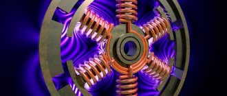
Among electrical machines designed to perform mechanical work, three-phase units are considered one of the most productive. The rotor rotates through the simultaneous influence of magnetic flux from the phase windings. Which ensures the simultaneous force of three moments at once, proportionally interacting with each other. How you can connect a three-phase motor, depending on their design features and the parameters of the electrical network, we will consider further.
general information
Connecting three-phase motors involves a relatively complex operation that requires an understanding of the processes occurring in the electrical installation. For this purpose it is necessary to consider both the constituent elements and their purpose.
Structurally, three-phase electric motors consist of:
- Stator with magnetic core;
- Rotor with shaft;
- Winding.
Depending on the type of engine, there are models with a squirrel cage or wound rotor. In some, the rotor rotates only due to the electromagnetic field induced from the stator windings, in others, the rotation of the shaft receives force from the rotor field when current flows in its windings. To turn on three-phase motors, you need to understand how the phases of the windings are connected to each other.
Differences between "star" and "triangle"
Based on the theory and practical knowledge of the basics of electrical engineering, the “star” connection method allows the electric motor to operate smoother and softer. But at the same time, this method does not allow the engine to reach the full power presented in the technical specifications.
By connecting the phase windings in a delta pattern, the motor is able to quickly reach maximum operating power. This allows you to use the full efficiency of the electric motor, according to the technical data sheet. But this connection scheme has its own drawback: large inrush currents. To reduce the value of currents, a starting rheostat is used, allowing for a smoother start of the engine.
Motor winding connection diagrams
In three-phase asynchronous electric motors, two connection options are used - star and delta. In three-phase asynchronous electrical machines, depending on the model, it is possible to implement the following scheme:
- Star;
- Triangle;
- Star and triangle.
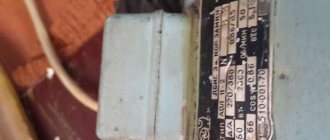
The simplest way to determine the capabilities of a particular asynchronous electric motor is to look at the nameplate (a metal plate with technical parameters). They also indicate the operating voltage rating for the corresponding connection. Here the designation can be indicated only for a star, only for a triangle, or both options at the same time; an example of such marking is shown in the figure below:
Example of designation on a nameplate
If the nameplate is missing or the information on it has been erased, then the connection diagram can be found by opening the winding start distribution block (BRNO). If you see 6 pins with terminal connections, you can determine the type of connection of the windings. It is much worse when the boron has only three terminals, and the connection is made inside the housing. In this case, you need to disassemble the three-phase electric motor to see the connection method.
Star
The star connection diagram for a three-phase motor provides that the beginning of each winding is combined into one point, and phases from the supply line are connected to their ends. This type provides a much smoother start and relatively gentle operation. However, the power with which the rotor rotates is one and a half times lower than when connected by a triangle. Schematically, this connection looks like this:
Star connection diagram
As you can see in the figure, the ends of the terminals of the three-phase motor windings A2, B2, C2 are connected into one electrical unit. And phase wires are connected to terminals A1, B1, C1, usually 220 or 380 volts.
If we consider this circuit using the example of Born, it will look like this:
Star connection of windings
Triangle
To connect an electric motor with a triangle, you need to bring the end of one winding to the beginning of the other. And thus close the windings into a kind of ring, at the connection points of which the leads of the supply line are connected. The triangle connection scheme provides maximum torque and force on the shaft, which is especially important for heavy loads. However, the current in the windings at rated load will also increase proportionally, not to mention overload conditions.
Therefore, turning on a three-phase motor with a delta requires a voltage reduction. For example, if the same electrical machine can be connected with both a triangle and a star winding connection, then the star will have a supply voltage of 380, and the triangle 220 volts or 220 and 127 volts, respectively. Schematically connecting the windings with a triangle will look like this:
Triangle connection diagram
As you can see, the connection is made from A2 to B1, from B2 to C1, from C2 to A1, in some models of electrical machines the markings of the terminals may differ, but on the cover of the burner their affiliation to a particular winding and possible options for connecting to each other will be displayed.
Triangle connection of windings
Conclusion
When working with electric current, follow safety precautions. Do not launch anything if you are not completely sure that the connection has been made correctly. Be sure to consult with an experienced electrician who will tell you whether the wiring can withstand the required load from the unit.
Recommended Posts
Electric motor connection diagram
How to make an electrical panel in the garage
Furniture LED lights for kitchen cabinets
Fan connection
Air conditioner installation rules
Plaster recessed luminaires
Connection options
Three-phase motors have excellent characteristics, a fairly wide range of models and are used in a wide variety of devices. Therefore, they are used both in industrial devices with three-phase power supply, and in household single-phase electrical installations. Next, we will analyze both options for connecting electrical machines.
To a single-phase network
The design feature of a three-phase unit, in contrast to single-phase asynchronous motors, is the need for a phase shift in the windings, otherwise the shaft will not rotate. To change the situation, one phase is divided for all three windings, two of which include additional inductance and starting capacitance. Which provide a shift in current and voltage relative to the voltage in the network. Inductance allows you to shift the voltage to the negative region up to -90°, but a single-phase capacitor, on the contrary, to the positive region up to +90°.
Graphically, the voltage-current lag function will look like this:
Change in current and voltage across capacitance and inductance
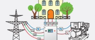
However, in practice, the bias is provided only by capacitive elements, which are included in the power supply circuit of one of the windings, and the other two are run between the phase and neutral wires. The connection diagram for a three-phase motor in a single-phase circuit is shown in the figure below:
Connection diagram to a single-phase network
As you can see in the figure, a tap is made from the phase wire containing a single-phase capacitor magazine of two elements, one for starting C2, the second for constant operation of C1. When the start button is pressed, contacts SA1 and SA2 close simultaneously, but after sufficient torque has been created and rotation has begun, SA1 is discarded and removes C1 from the circuit, leaving C2. Power, with this engine switching scheme, is reduced to 30 - 50%.
Capacitor starting is calculated using the formula:
Serb = (2800*I)/U - to turn on a three-phase motor with a star
Crab = (4800*I)/U - to turn on a three-phase motor with a triangle
The starting capacitor is used only in loaded starting, so it can not be used in light starting. Then, instead of the launcher capacity, the worker will be used.
To a three-phase network
In a three-phase network, despite the presence of the required type of supply voltage, a magnetic starter is always used to drive the motor into rotation. Starting without a starter or contactor is quite dangerous, so they are an integral element.
Connection diagram to a three-phase network
The figure above shows a typical diagram for connecting a motor to a three-phase network, which works on the following principle:
- Voltage is supplied to the engine from the mains through switch 1.
- further, when the start button 6 is turned on, the contactor coil 4 is powered, which attracts the power contacts of the starter 3;
- after which the engine begins to rotate, and the start button 6 is bridged through the repeater 5;
- to stop the three-phase motor, use the Stop button - 7, which is in the normally closed position;
- Motor overload protection monitors the current load in the network and, if a threat arises, opens contacts 2.
This diagram can be simplified due to the design features of the starters used. Since some of them are manufactured without repeaters, they may have the function of reversing a three-phase motor or be produced without protection. You can get more detailed information about magnetic starters from the corresponding article on the website:
Selection of capacitor
There are no universal capacitors that would fit all units indiscriminately. Their characteristic is the capacity they are able to hold. Therefore, each one will have to be selected individually. The main requirement for it will be operation at a network voltage of 220 volts; more often they are designed for 300 volts. To determine which element is required, you need to use the formula. If the connection is made by a star, then it is necessary to divide the current by a voltage of 220 volts and multiply by 2800. The current indicator is taken from the figure indicated in the engine characteristics. For a triangle connection, the formula remains the same, but the last coefficient changes to 4800.
For example, if it is written on the unit that the rated current that can flow through its windings is 6 amperes, then the capacity of the working capacitor will be 76 µF. This is when connected by a star; for a delta connection the result will be 130 µF. But it was said above that if the unit experiences a load at start-up or has a power of more than 1.5 kW, then another capacitor will be needed - a starting capacitor. Its capacity is usually 2 or 3 times the working one. That is, for a star connection you will need a second capacitor with a capacity of 150–175 μF. You will have to select it experimentally. There may not be capacitors of the required capacity on sale, then you can assemble a unit to obtain the required figure. To do this, the available capacitors are connected in parallel so that their capacitance adds up.
Note! There is some limitation on the power of three-phase units that can be powered from a single-phase network. It is 3 kW. If this value is exceeded, the wiring may fail.
Why is it better to select starting capacitors empirically, starting with the smallest? The fact is that if its value is insufficient, a higher current will be supplied, which can damage the windings. If its value is greater than the required one, then the unit will not have enough impulse to start. You can more clearly imagine the connection using a video.