Schematic electrical diagrams, connecting devices and pinouts of connectors
There are 2 types of single-phase asynchronous motors - bifilar (with a starting winding) and capacitor. Their difference is that in bifilar single-phase motors the starting winding operates only until the motor accelerates. Afterwards it is turned off by a special device - a centrifugal switch or a start-up relay (in refrigerators). This is necessary because after overclocking it reduces efficiency.
In capacitor single-phase motors, the capacitor winding runs all the time. Two windings - the main and auxiliary, they are shifted relative to each other by 90°. Thanks to this, you can change the direction of rotation. The capacitor on such engines is usually attached to the housing and is easy to identify by this feature.
Connection diagram for a single-phase motor via a capacitor
When connecting a single-phase capacitor motor, there are several options for connection diagrams. Without capacitors, the electric motor hums, but does not start.
- 1 circuit - with a capacitor in the power supply circuit of the starting winding - starts well, but during operation the power it produces is far from rated, but much lower.
- 3, the connection circuit with a capacitor in the connection circuit of the working winding gives the opposite effect: not very good performance at start-up, but good performance. Accordingly, the first circuit is used in devices with heavy starting, and with a working capacitor - if good performance characteristics are needed.
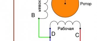
- Diagram 2 - connecting a single-phase motor - install both capacitors. It turns out something between the options described above. This scheme is used most often. She's in the second picture. When organizing this circuit, you also need a PNVS type button, which will connect the capacitor only during the start time, until the motor “accelerates”. Then two windings will remain connected, with the auxiliary winding through a capacitor.
AIRE80S4 electric motor 1.5 kW 1410 rpm (single-phase 220) Elmash Russia
It is carried out from a network with a voltage of 220/230 Volts, alternating current with a frequency of 50 Hz. It is optimal to position the motors in such a way that they are protected from significant temperature changes, since these can have a negative impact on the correct operation of the capacitor. If temperature fluctuations occur, periodic checking of the capacitor is necessary.
The stator windings are made of high-quality copper, coated with varnish in compliance with all necessary technological processes, the main purpose of which is to increase the service life of the stator insulating coating. Single-phase electric motor AIRE80S4 asynchronous capacitor motor, power 1.5 kW, belongs to high-speed motors, rotation speed reaches 1500 rpm . They are equipped with a squirrel cage type rotor.
Connection diagram for a single-phase motor (capacitor)
There are 6 pins located on the terminal block of such a motor; these pins are connected in the following order: U1 and U2 are the main winding, Z1 and Z2 are the auxiliary winding. The dotted area is the working capacitor.
To connect the motor in the reverse direction, you need to apply an alternating voltage ~220 (V) to the same terminals W2 and V1, and place the jumpers as shown in the picture below, i.e. between terminals U1-V1 and W2-U2.
To connect the motor in the forward direction, you need to apply an alternating voltage ~220 (V) to terminals W2 and V1, and place jumpers as shown in the picture below, i.e. between terminals U1-W2 and V1-U2.
If you have a need to purchase this type of equipment, buying a single-phase electric motor AIRE80S4 “ELMASH” with a voltage of 220 Volts will not be a problem. To do this, call 8 (800) 700-30-67 toll-free throughout Russia or place an online order on our website www.agregat.me or write by email. The order will be accepted and processed immediately.
agregat.me
Connection diagram for a three-phase motor via a capacitor
Here, the voltage of 220 volts is distributed into 2 series-connected windings, where each is designed for this voltage. Therefore, the power is lost almost twice, but such an engine can be used in many low-power devices.
The maximum power of a 380 V motor in a 220 V network can be achieved using a delta connection. In addition to minimal power losses, the engine speed also remains unchanged. Here, each winding is used for its own operating voltage, hence the power.
It is important to remember: three-phase electric motors have higher efficiency than single-phase 220 V motors . Therefore, if there is a 380 V input, be sure to connect to it - this will ensure more stable and economical operation of the devices. To start the motor, you will not need various starters and windings, because a rotating magnetic field appears in the stator immediately after connecting to a 380 V network.
Download
If the topic interests you more deeply, I recommend that you read the literature listed on the page.
Here is one of the books listed there: • Lomonosov, V.Yu.; Polivanov, K.M.; Mikhailov, O.P. Electrical engineering. / Lomonosov, V.Yu.; Polivanov, K.M.; Mikhailov, O.P. Electrical engineering. One of the best books on the basics of electrical engineering. The presentation begins with the very basics: it explains what voltage, current and resistance are, provides instructions for calculating the simplest electrical circuits, and talks about the relationship and interdependence of electrical and magnetic phenomena. Explains what alternating current is and how an alternating current generator works. It describes what a capacitor is and what an inductor is, what their role is in alternating current circuits. It is explained what three-phase current is, how three-phase current generators are designed and how its transmission is organized. A separate chapter is devoted to semiconductor devices: it talks about semiconductor diodes, transistors and thyristors; on the use of semiconductor devices for rectifying alternating current and as semiconductor switches. The achievements of microelectronics are briefly described. The last third of the book is entirely devoted to electrical machines, units and equipment: chapter 10 deals with direct current machines (generators and motors); Chapter 11 is devoted to transformers; AC machines (single-phase and three-phase, synchronous and asynchronous) are described in detail in Chapter 12; switches, electromagnets and relays are described in Chapter 13; Chapter 14 deals with electrical diagramming. The last, chapter 15, is devoted to measurements in electrical engineering. This book is a great way to learn the basics of electrical engineering, to understand the fundamental principles of the operation of electrical machines and units., zip, 13.87 MB, downloaded: 2653 times./
Schemes for the article in the SPlan program
• 2-speed motor / Schemes for the article https://www.samelectric.ru/promyshlennoe-2/podklyuchenie-dvuhskorostnogo-asinhronnogo-dvigatelya.html, zip, 14.44 kB, downloaded: 2202 times./
Online calculation of motor capacitor capacity
Enter data for calculating capacitors - motor power and efficiency
There is a special formula that can be used to calculate the required capacity accurately, but you can easily get by with an online calculator or recommendations that are derived from many experiments:
The working capacitor is taken at the rate of 0.8 μF per 1 kW of engine power; The launcher is selected 2-3 times more.
Capacitors must be non-polar, that is, not electrolytic. The operating voltage of these capacitors must be at least 1.5 times higher than the network voltage, that is, for a 220 V network we take capacitors with an operating voltage of 350 V and higher. To make starting easier, look for a special capacitor in the starting circuit. They have the words Start or Starting in their markings.
Starting capacitors for motors
These capacitors can be selected using the method from smallest to largest. Having thus selected the average capacity, you can gradually add and monitor the operating mode of the engine so that it does not overheat and has enough power on the shaft. Also, the starting capacitor is selected by adding until it starts smoothly without delays.
During normal operation of three-phase asynchronous electric motors with capacitor start, connected to a single-phase network, it is assumed that the capacitance of the capacitor will change (decrease) with increasing shaft speed. At the moment of starting asynchronous motors (especially with a load on the shaft) in a 220 V network, an increased capacity of the phase-shifting capacitor is required.
AIRE 80 C2
e-mail:
Home About the company Prices Delivery GOST Contacts Brands AIRAIREMTFMTN4MTNMTKAIMT10ARMAR5AMNDAN5AI4MTM Special offer! Call from the manager Model Power, kW Rotation speed, rpm.
| AIRE 80 C2 | 2.2 kW | 2820 rpm | Order |
| l1 | l10 | l31 | d1 | b1 | b10 | h2 | h5 | h20 | h |
| 50 | 100 | 50 | 22 | 6 | 125 | 6 | 24.5 | 8 | 80 |
| power, kWt | Rotation speed, rpm | Voltage, V | Efficiency | Kf. power | Iп/Iн | Weight |
| 2.2 | 3000 | 220 | 76% | 0.9 | 4 | 16 |
AIRE 80 C2 is an asynchronous single-phase electric motor with an attached working capacitor. A mandatory part of industrial and household machines and devices that do not require adjustment of the movement frequency: machine tools, compressors, pumps, conveyors. Designed for long-term operation of S1, it can easily withstand voltage surges and frequent stops and starts. The sulamin alloy housing with protection degree IP 54 prevents moisture and dust from entering the motor; lacquered copper winding with heat resistance degree F ensures resistance to prolonged heating up to 150 °C inclusive. Unit power - 2.2 kW, rotation speed - 2820 rpm.
PromTehMash LLC | 2003 - 2022 | All rights reserved 8 (812) 414-78-878
electrodvigateli.ru
Reversing the direction of movement of the engine
If, after connecting, the motor works, but the shaft does not rotate in the direction you want, you can change this direction. This is done by changing the windings of the auxiliary winding. This operation can be performed by a two-position switch, the central contact of which is connected to the output from the capacitor, and to the two outer terminals from “phase” and “zero”.
A single-phase motor operates using alternating electric current and is connected to single-phase networks. The network must have a voltage of 220 Volts and a frequency of 50 Hertz.
Electric motors of this type are used mainly in low-power devices:
- Household appliances.
Low power fans- Pumps.
- Machines
for processing raw materials, etc.
Models are available with power from 5 W to 10 kW.
The values of efficiency, power and starting torque for single-phase motors are significantly lower than for three-phase devices of the same size. The overload capacity is also higher for 3-phase motors. Thus, the power of a single-phase mechanism does not exceed 70% of the power of a three-phase mechanism of the same size.
device
- In fact, it has 2 phases
, but only one of them does the work, which is why the motor is called single-phase. - Like all electric machines
, a single-phase motor consists of 2 parts: stationary (stator) and moving (rotor). - It is a
stationary component of which has one working winding connected to a single-phase alternating current source.
The strengths of this type of engine include the simplicity of the design, which is a rotor with a squirrel-cage winding. The disadvantages are low starting torque and efficiency.
The main disadvantage of single-phase current
– the impossibility of generating a magnetic field that performs rotation. Therefore, a single-phase electric motor will not start on its own when connected to the network.
In the theory of electrical machines, the following rule applies:
In order for a magnetic field to arise that rotates the rotor, there must be at least 2 windings (phases) on the stator. It is also required to shift one winding by a certain angle relative to the other.
During operation, alternating electric fields flow around the windings:
- In accordance with this
, the so-called starting winding is located on the stationary section of the single-phase motor. It is shifted 90 degrees relative to the working winding. - A current shift
can be obtained by including a phase-shifting link in the circuit. Active resistors, inductors and capacitors can be used for this.
2212 electrical steel is used as the basis
It is incorrect to call single-phase electric motors that are 2- and 3-phase in structure, but are connected to a single-phase power source through matching circuits (capacitor electric motors). Both phases of such devices are working and are turned on all the time.
Read also: Control circuit for two thyristors
Single-phase electric motor AIRE 80 C2 in Ufa
Single-phase AC electric motors are intended for equipping electric drives of mechanisms for various purposes in all industries, drives of the agricultural complex, household appliances (woodworking machines, pumps, compressors, etc.) and household small-scale mechanization equipment (feed choppers, concrete mixers, etc.). Frequency 50Hz, voltage 220V, protection degree IP54, insulation class F.
Mounting options: paws (IM1001), flange (IM3001), combi (IM2001).
Climatic modification - U2, U3, UHL4.
Single-phase asynchronous electric motors are usually produced with low power; unlike three-phase ones, they have a single-phase winding on the stator. The rotor of such a motor has a short-circuited winding. Since single-phase current does not create a rotating magnetic field, hence single-phase motors have no starting or starting torque. To create a starting torque, a second, so-called starting winding is placed on the engine stator, shifted relative to the working winding at an angle of 90°. Both windings are powered from a single-phase current network. To create a phase shift between the currents of both windings, a large active resistance or capacitance is turned on.
Single-phase asynchronous motors have the following disadvantages compared to three-phase ones:
- low starting torque;
- low overload capacity;
- lower efficiency;
- lower power factor.
The overall dimensions of single-phase electric motors AIR correspond to the overall dimensions of electric motors of 5AI engines
ModelWeight, kg (IM 1081)Power, kWInom, Amput—-Mnom Mmax—-MnomRotation frequency, rpm AIRE80 B4 AIRE80 A4 AIRE80 C4 AIRE80 A2 AIRE80 B2 AIRE80 C2 AIRE90 L4 AIRE90 L2 AIRE90 L2 D
| 14,1 | 1,1 | 7,2 | 0,35 | 1,5 | 1500 |
| 12,5 | 0,75 | 5,1 | 0,35 | 1,6 | 1500 |
| 16,1 | 1,5 | 9,7 | 0,40 | 1,6 | 1500 |
| 13,0 | 1,1 | 7,4 | 0,50 | 1,7 | 3000 |
| 15,8 | 1,5 | 10,0 | 0,50 | 1,8 | 3000 |
| 17,8 | 2,2 | 13,9 | 0,55 | 1,8 | 3000 |
| 17,9 | 1,5 | 9,7 | 0,40 | 1,6 | 1500 |
| 17,8 | 2,2 | 13,9 | 0,55 | 1,8 | 3000 |
| 17,7 | 2,2 | 13,9 | 0,55 | 1,8 | 3000 |
Starting scheme:
| Type | R, kW | U, V | Efficiency, % | Сos j | Slip, % | Mn/Mn | Mmax/Mn | Iп/Iн | S, mkf | Uns, V | Weight, kg |
| Synchronous speed 3000 rpm | |||||||||||
| AIRE56A2 | 0,12 | 220/230 | 62,0 | 0,92 | 5,5 | 0,5 | 2,5 | 3,2 | 6,3 | 450 | 3,7 |
| AIRE56V2 | 0,18 | 220/230 | 65,0 | 0,95 | 5,5 | 0,45 | 2,1 | 2,8 | 8,0 | 450 | 4,0 |
| AIRE56S2 | 0,25 | 220/230 | 62,0 | 0,95 | 6,0 | 0,55 | 2,0 | 3,0 | 12,5 | 450 | 4,3 |
| AIRE63V2 | 0,37 | 220 | 68,0 | 0,84 | 5,0 | 0,52 | 2,6 | 4,0 | 20,0 | 450 | 6,3 |
| 230 | 16,0 | 450 | |||||||||
| AIRE71A2 | 0,55 | 115 | 75,0 | 0,9 | 5,0 | 0,50 | 2,0 | 4,3 | 30,0 | 250 | 8,9 |
| 220/230 | 16,0 | 450 | |||||||||
| AIRE71B2 | 0,75 | 115 | 71,0 | 0,84 | 7,0 | 0,55 | 1,9 | 4 | 50,0 | 250 | 9,6 |
| 220/230 | 25,0 | 450 | |||||||||
| AIRE71S2 | 1,10 | 115 | 70,0 | 0,85 | 7,0 | 0,55 | 2,0 | 3,8 | 60,0 | 250 | 10,5 |
| 220/230 | 30,0 | 450 | |||||||||
| AIRE80V2 | 1,50 | 115 | 76,0 | 0,95 | 7,0 | 0,45 | 1,9 | 4,0 | 80,0 | 250 | 15,1 |
| 220/230 | 40,0 | 450 | |||||||||
| AIRE80S2,S1/S6-40% | 1,8/2,2 | 115 | 76,0 | 0,9 | 8,0 | 0,45 | 1,7 | 4,0 | 100,0 | 250 | 15,9 |
| 220/230 | 50,0 | 450 | |||||||||
| Synchronous speed 1500 rpm | |||||||||||
| AIRE56A4 | 0,12 | 220/230 | 50,0 | 0,88 | 7,0 | 0,55 | 1,8 | 2,0 | 8,0 | 450 | 3,8 |
| AIRE56V4 | 0,18 | 220/230 | 55,0 | 0,9 | 7,5 | 0,50 | 1,65 | 2,2 | 12,5 | 450 | 4,4 |
| AIRE63V4 | 0,25 | 220 | 60,0 | 0,8 | 5,0 | 0,52 | 1,9 | 2,6 | 10,0 | 450 | 6,2 |
| 230 | 8,0 | 250 | |||||||||
| AIRE71A4 | 0,37 | 115 | 64,0 | 0,9 | 9,5 | 0,60 | 2,0 | 3,0 | 25,0 | 250 | 8,3 |
| 220/230 | 14,0 | 450 | |||||||||
| AIRE71B4 | 0,55 | 115 | 69,0 | 0,9 | 10,5 | 0,60 | 1,8 | 3,0 | 30,0 | 250 | 9,6 |
| 220/230 | 16,0 | 450 | |||||||||
| AIRE71S4 | 0,75 | 115 | 64,0 | 0,88 | 10,0 | 0,55 | 1,6 | 3,0 | 50,0 | 250 | 10,3 |
| 220/230 | 25,0 | 450 | |||||||||
| AIRE80V4 | 1,10 | 115 | 71,0 | 0,9 | 10,0 | 0,45 | 1,8 | 3,0 | 60,0 | 250 | 14,1 |
| 220/230 | 30,0 | 450 | |||||||||
| AIRE80S4,S1/S6-60% | 1,3/1,5 | 115 | 71,0 | 0,95 | 11,0 | 0,45 | 1,55 | 2,8 | 80,0 | 250 | 15,1 |
| 220/230 | 35,0 | 450 | |||||||||
| AIRE100S4 | 2,20 | 220 | 75,0 | 0,95 | 6,5 | 0,40 | 1,9 | 3,2 | 60,0 | 450 | 24,4 |
| Type | R, kW | U, V | Efficiency, % | Сos j | Slip, % | Mn/Mn | Mmax/Mn | Iп/Iн | S, mkf | Uns, V | Weight, kg |
| Synchronous speed 3000 rpm | |||||||||||
| AIR3E56A2 | 0,12 | 220 | 65,0 | 0,92 | 6,0 | 0,50 | 2,5 | 3,0 | 12,5 | 250 | 3,6 |
| AIR3E56B2 | 0,18 | 68,0 | 0,92 | 0,50 | 2,1 | 3,0 | 20 | 250 | 3,9 | ||
| AIR3E56S2 | 0,25 | 62,0 | 0,92 | 0,60 | 2,2 | 3,0 | 30 | 250 | 4,1 | ||
| AIR3E63B2 | 0,37 | 70,0 | 0,95 | 0,65 | 2,1 | 3,5 | 40 | 250 | 6,3 | ||
| AIR3E80A2 | 1,10 | 68,0 | 0,98 | 0,30 | 1,6 | 3,5 | 80 | 250 | 12,4 | ||
| AIR3E80V2 | 1,50 | 70,0 | 0,98 | 0,32 | 1,6 | 3,2 | 120 | 250 | 15 | ||
| Synchronous speed 1500 rpm | |||||||||||
| AIR3E56A4 | 0,12 | 220 | 57,0 | 0,9 | 7,0 | 0,60 | 1,8 | 2,0 | 16 | 250 | 3,7 |
| AIR3E56B4 | 0,18 | 57,0 | 0,95 | 0,65 | 1,6 | 2,0 | 25 | 250 | 4,4 | ||
| AIR3E63B4 | 0,25 | 62,0 | 0,95 | 6,0 | 0,50 | 2,0 | 2,8 | 35 | 250 | 6,2 | |
| AIR3E80A4 | 0,75 | 67,0 | 0,94 | 5,0 | 0,50 | 2,0 | 3,2 | 80 | 250 | 11,9 | |
| AIR3E80V4 | 1,10 | 72,0 | 0,97 | 0,50 | 1,7 | 3,0 | 100 | 250 | 13,8 | ||
Notes:
- C – nominal capacity of the working capacitor, μF;
- Uns – rated voltage of the working capacitor, V.
Single-phase asynchronous motors of size 80 can be equipped with a control unit to increase the starting torque (Mn/Mn>1). The control unit consists of starting and running capacitors, a starting relay and a current protection relay. The control unit turns on the starting capacitor in engine starting mode and during overloads.
The dimensions and technical characteristics of the engines correspond to the catalog for AIR 80 engines, with the exception of sizes h and MP.
elektrodvigateli-ufa.ru
Operating principle and startup scheme
- An electric current
generates a pulsating magnetic field on the motor stator. This field can be considered as 2 different fields that rotate in different directions and have equal amplitudes and frequencies. - When the rotor is stationary
, these fields lead to the appearance of moments of equal magnitude, but differently directed. - If the engine does not have special starting mechanisms
, then at start the resulting torque will be zero, which means the engine will not rotate. - If the rotor is rotated in one direction
, then the corresponding torque begins to prevail, which means that the motor shaft will continue to rotate in the given direction.
- The launch is carried out by a magnetic field
, which rotates the moving part of the motor. It is created by 2 windings: main and additional. The latter is smaller in size and is a launcher. It is connected to the main electrical network through capacitance or inductance. The connection is made only during start-up. In low power motors, the starting phase is short-circuited. - The engine
is started by holding the start button for a few seconds, as a result of which the rotor accelerates. - When the start button is released
, the electric motor switches from two-phase mode to single-phase mode, and its operation is supported by the corresponding component of the alternating magnetic field. - The starting phase
is designed for short-term operation – usually up to 3 s. A longer time under load can lead to overheating, insulation fire and mechanism failure. Therefore, it is important to release the start button in a timely manner. - In order to increase reliability,
a centrifugal switch and a thermal relay are built into the housing of single-phase motors. - The function of the centrifugal switch
is to cut off the starting phase when the rotor reaches its rated speed. This happens automatically - without user intervention. - The thermal relay
turns off both phases of the winding if they heat up above the permissible level.
Principle of operation
Flowing through the main winding creates a periodically changing magnetic field. It consists of two circles of the same amplitude, the rotation of which occurs towards each other.
2. Starters, for example, are divided by a value from 1 to 7, and the higher this indicator, the greater the current the contact system of these devices can withstand.
- 10A - 1.
- 25A - 2.
- 40A - 3.
- 63A - 4.
- 80A - 5.
- 125A - 6.
- 200A - 7.
3. After the starter size has been determined, you need to pay attention to the control coil. It can be 36B, 380B and 220B. It is advisable to focus on the last option.
5. The “Stop - Start” buttons are connected. They are powered from the input power contacts of the starter. For example, a phase is connected to the “Stop” button of a closed contact, then from it it goes to the start button of an open contact, and from the contact of the “Start” button to one of the contacts of the magnetic starter coil.
6. “Zero” is connected to the second terminal of the starter. To fix the on position of the magnetic starter, it is necessary to bypass the start button of the closed contact to the contact block of the starter, which supplies power from the “Stop” button to the coil.
Single-phase motors are used for various household appliances. They are found in pumps and washing machines. If necessary, you can repair and connect such a unit with your own hands and check its winding. To connect a single-phase electric motor, you need to select a circuit and then follow the process exactly.
What is a single-phase motor? In this case, the current creates a magnetic pulsating field with different amplitudes during operation. This is what makes the resulting torque equal to zero when starting the motor; without a special device it simply will not start rotating. If the rotor is set in motion in one direction or another (that is, its rotation is observed), then one moment begins to prevail over the other, the motor shaft continues to move.
The motor is started due to the appearance of a magnetic rotating field. The number of windings is two, the rotor is squirrel-cage. Basically, single-phase motors are used for low-power devices, for example, for household appliances, for fans, pumps, for drilling water wells.
Connection
To operate the device, 1 phase with a voltage of 220 Volts is required. This means that you can plug it into a household outlet. This is precisely the reason for the popularity of the engine among the population. All household appliances, from a juicer to a grinder, have mechanisms of this type.
connection with starting and running capacitors
There are 2 types of electric motors: with a starting winding and with a working capacitor:
- In the first type of device
, the starting winding operates via a capacitor only during start. Once the machine reaches normal speed, it turns off and operation continues with one winding. - In the second case
, for motors with a working capacitor, the additional winding is permanently connected through the capacitor.
An electric motor can be taken from one device and connected to another. For example, a working single-phase motor from a washing machine or vacuum cleaner can be used to operate a lawn mower, processing machine, etc.
There are 3 schemes for switching on a single-phase motor:
- In scheme 1
, the work of the starting winding is performed by means of a capacitor and only for the starting period. - 2 circuit
also provides for a short-term connection, but it occurs through a resistance and not through a capacitor. - Scheme 3
is the most common. In this scheme, the capacitor is constantly connected to a source of electricity, and not just during startup.
Connecting an electric motor with starting resistance:
- The auxiliary winding
of such devices has increased active resistance. - To start an electrical machine
of this type, a starting resistor can be used. It should be connected in series to the starting winding. Thus, it is possible to obtain a phase shift of 30° between the winding currents, which will be quite enough to start the mechanism. - Alternatively
, a phase shift can be obtained by using a starting phase with a higher resistance value and a lower inductance value. This winding has fewer turns and thinner wire.
Connecting a motor with capacitor start:
- For these electric machines,
the starting circuit contains a capacitor and is turned on only for the start period. - To achieve the maximum
starting torque, a circular magnetic field is required that performs the rotation. For it to occur, the winding currents must be rotated 90° relative to each other. Phase-shifting elements such as a resistor and inductor do not provide the necessary phase shift. Only the inclusion of a capacitor in the circuit allows you to obtain a phase shift of 90°, if you select the capacitance correctly. - calculate
which wires belong to which winding by measuring the resistance. For the working winding, its value is always less (about 12 Ohms) than for the starting winding (usually about 30 Ohms). Accordingly, the cross-section of the working winding wire is larger than that of the starting winding. - The capacitor
is selected according to the current consumed by the motor. For example, if the current is 1.4 A, then a capacitor with a capacity of 6 μF is required.
Geometric dimensions of the 90L-2 asynchronous electric motor.
| G | 20 | |
| D | 24 | |
| F | 8 | |
| D.H. | M8X19 | |
| E | 50 |
| A.C. | 195 | |
| AD | 145 | |
| H | 90 | |
| KK | M20 | |
| L | 330 | |
| Q | 5 | |
| M | 165 | |
| N | 130 | |
| P | 200 | |
| R | ||
| S | 12 | |
| T | 3.5 |
Functionality check
How to check engine performance by visual inspection?
The following are defects that indicate possible problems with the engine; they could be caused by improper operation or overload:
- Broken support
or mounting gaps. - in the middle of the engine
has darkened (indicates overheating). - through cracks
in the housing.
To check the performance of the engine, you should first turn it on for 1 minute, and then let it run for about 15 minutes.
If after this the engine is hot, then:
- Perhaps
the bearings are dirty, jammed, or simply worn out. - The reason
may be that the capacitor capacitance is too high.
Disconnect the capacitor and start the motor manually: if it stops heating, you need to reduce the capacitor capacitance.
Sharpening machine (sharpener) on a Dahlander engine
I recently came across a sharpening machine with a two-speed motor, I am posting its diagram.
Scheme of a sharpening machine on a two-speed Dahlander motor
I am often asked what kind of protection should be given to this engine? Here, in the diagram, is a simple thermal relay (PT1), configured for a higher current (about 11 A).
Here is the engine nameplate:
Parameters of two-speed sharpening machine motor
And here are his pin designations:
Two-speed motor terminals
Why do you think the rectangle PS (speed switch) is shown instead of the connection diagram? That's right, the circuit would then be 2 times larger and more complex.
Model overview
One of the most popular are electric motors of the AIR series.
There are models made on feet 1081, and models of combined design - feet + flange 2081.
Electric motors in the foot + flange design will cost about 5% more than similar ones with feet.
As a rule, manufacturers provide a warranty of 12 months.
For electric motors with a rotation height of 56-80 mm, the frame is made of aluminum. Motors with a rotation height of more than 90 mm are available in cast iron.
Models differ in power, rotation speed, height of the rotation axis, and efficiency.
The more powerful the engine, the higher its cost:
- An engine with a power of 0.18 kW
can be purchased for 3 thousand rubles (electric motor AIRE 56 B2). - A model with a power of 3 kW
will cost about 10 thousand rubles (AIRE 90 LB2).
As for the rotation speed, the most common models are with frequencies of 1500 and 3000 rpm, although there are engines with other frequency values. With equal power, the cost of an engine with a speed of 1500 rpm is slightly higher than that of one with a speed of 3000 rpm.
The height of the rotation axis for motors with 1 phase varies from 56 mm to 90 mm and directly depends on the power: the more powerful the engine, the greater the height of the rotation axis, and therefore the price.
Different models have different efficiencies, typically ranging from 67% to 75%. Greater efficiency corresponds to a higher cost of the model.
You should also pay attention to engines produced by the Italian company AACO, founded in 1982:
- Thus, the AACO series 53 electric motor
is designed specifically for use in gas burners. These motors can also be used in washing installations, warm air generators, and central heating systems. - Electric motors of the 60, 63, 71 series
are designed for use in water supply installations. Also, the company offers universal motors of the 110 and 110 compact series, which are distinguished by a diverse range of applications: burners, fans, pumps, lifting devices and other equipment.
You can buy motors produced by AACO for a price starting from 4,600 rubles.
There are often cases when it is necessary to connect an electric motor to a 220 volt network - this happens when you try to adapt the equipment to your needs, but the circuit does not meet the technical characteristics specified in the passport of such equipment. In this article we will try to analyze the main methods for solving the problem and present several alternative circuits with a description for connecting a single-phase electric motor with 220 volt condensate.
Read also: Conditions for burning a welding arc
Why is this happening? For example, in a garage you need to connect a 220-volt asynchronous electric motor, which is designed for three phases. At the same time, it is necessary to preserve the efficiency (efficiency factor), this is done if an alternative (in the form of an engine) simply does not exist, because in a three-phase circuit a rotating magnetic field is easily formed, which ensures the creation of conditions for the rotation of the rotor in the stator. Without this, the efficiency will be lower compared to a three-phase connection diagram.
When there is only one winding in single-phase motors, we see a picture where the field inside the stator does not rotate, but pulsates, that is, the starting push does not occur until the shaft is untwisted with one’s own hand. In order for rotation to occur independently, we add an auxiliary starting winding. This is the second phase, it is moved 90 degrees and pushes the rotor when turned on. In this case, the motor is still connected to a single-phase network, so the name single-phase is retained. Such single-phase synchronous motors have working and starting windings. The difference is that the starter is active only when the rotor is turned on, working for only three seconds. The second winding is on all the time. In order to determine which is which, you can use a tester. In the figure you can see their relationship with the circuit as a whole.
Connecting a 220-volt electric motor: the motor starts by supplying 220 volts to the working and starting windings, and after reaching the required speed, you must manually turn off the starting winding. In order to shift the phase, ohmic resistance is necessary, which is provided by inductive capacitors. There is resistance both in the form of a separate resistor and in part of the starting winding itself, which is performed using the bifilar technique. It works like this: the inductance of the coil is maintained, but the resistance becomes greater due to the elongated copper wire. Such a diagram can be seen in Figure 1: connecting a 220 volt electric motor.
Figure 1. Connection diagram for a 220 volt electric motor with a capacitor
There are also motors in which both windings are continuously connected to the network; they are called two-phase, because the field inside rotates, and a capacitor is provided to shift the phases. To operate such a circuit, both windings have a wire with a cross-section equal to each other.
AIRE80C2
Electric motor AIRE80S2 220V 2.2 kW*3000 rpm Price Buy
Asynchronous electric motors AIRE80S2 with a rated power of N=2.2 kilowatts (kW) and a rotation speed of n=3000 revolutions per minute (rpm) are used in drives of various electrical structures and units. The main task of an electric motor is to convert electrical energy into mechanical energy, which gives movement and rotation to various mechanisms and parts.
Decoding AIRE80S2 U1, AIR80S2 U2, AIR80S2 U3:
A - AsynchronousI - Interelectro (motor developer)P - option for linking power to installation dimensions according to RS3031-71E - single-phase (220V)80 - distance from the bottom of the paws to the center of the shaft in millimetersC - third option for core length2 - number of connected poles of the electric motorU1 - climatic version : moderate outdoor climateU2 - climatic version: moderate outdoor climate under a canopyU3 - climatic version: moderate indoor climate
AIRE 80S2 electric motors are produced in the main mounting version - on feet with bearing shields (IM1081 or IM1001). It is possible to manufacture in a combined version - on feet and with a flange (IM2081 or IM2001).
Decoding of installation versions of AIR electric motors in accordance with GOST 2479
Feet Combi Flange
IM - mounting design First digit - design: 1 - motor on feet with bearing shields 2 - motor on feet with bearing shields and a flange on one bearing shield 3 - motor without legs, with a flange on one bearing shield Second and third digits - installation method Fourth digit - design shaft:1 - with one cylindrical shaft end2 - with two cylindrical shaft ends
Standard version of electric motors AIRE80S2:
Climatic modification U2 (moderate climate, outdoors under a canopy) Rated voltage 220 V at a frequency of 50 Hz Protection degree IP55 (protection from dust and water jets from all sides)
Overall dimensions of AIRE80S2 electric motors
| Weight, kg | Number of poles | Dimensions, mm | |||||||||||||||
| l30 | h41 | d24 | l1 | l10 | l31 | d1 | d10 | d20 | d22 | d25 | b10 | n | h | h5 | b1 | ||
| 15 | 2 | 300 | 207 | 200 | 50 | 100 | 50 | 22 | 10 | 165 | 11 | 130 | 125 | 4 | 80 | 24,5 | 6 |
Order
armavent.ru
Connection diagram for a 220 volt commutator motor
Where can you find it in everyday life?
Electric drills, some washing machines, hammer drills and grinders have a synchronous commutator motor. It is capable of operating in single-phase networks even without triggers. The scheme is as follows: a jumper connects ends 1 and 2, the first originates in the armature, the second in the stator. The two tips that remain must be connected to a 220 volt power supply.
Connecting a 220 volt electric motor with a starting winding
- This scheme excludes the electronics unit, and therefore, the motor will immediately operate at full power from the moment of start - at maximum speed, when starting, literally breaking off with force from the starting electric current, which causes sparks in the collector;
- There are electric motors with two speeds. They can be identified by the three ends in the stator coming out of the winding. In this case, the speed of the shaft during connection decreases, and the risk of insulation deformation at start increases;
- The direction of rotation can be changed by swapping the ends of the connection in the stator or armature.
Basic parameters of the 90L-2 electric motor.
| Parameter | Meaning | Explanations |
| Nominal torque (C n), N*m | 7.49 | The rated torque of an electric motor depends on power and speed. It is calculated as the product of the force and the radius of the shaft. |
| Ratio of starting torque (C s) to nominal | 2.9 | Starting torque is the torque that the engine must develop in order to get off the ground and develop the installed power. |
| Ratio of maximum torque (C max) to rated motor torque | 3 | The maximum torque produced by a motor of a certain rated power at a certain speed. Maximum torque also represents the amount of resistance at which the engine stops. |
| Rated current In, A | 4.75 | The current consumed by a motor when rated voltage is applied to achieve rated power. For another applied voltage, the current consumption is calculated proportional to that voltage. |
| Ratio of motor starting current I s to rated current | 5.2 | |
| Noise, dB | 72 | |
| Electric motor weight, kg | 14 |
Connection diagram for a 380 to 220 volt electric motor with a capacitor
There is another option for connecting an electric motor with a power of 380 Volts, which starts moving without load. This also requires a capacitor in working order.
One end is connected to zero, and the other to the output of the triangle with serial number three. To change the direction of rotation of the electric motor, it is worth connecting it to a phase, and not to zero.
Connection diagram for a 220 volt electric motor through capacitors
In the case when the engine power is more than 1.5 Kilowatts or when it starts working immediately with a load, it is necessary to install a starting capacitor in parallel with the working capacitor. It serves to increase the starting torque and turns on for only a few seconds during the start. For convenience, it is connected with a button, and the entire device is powered via a toggle switch or a button with two positions, which has two fixed positions. In order to start such an electric motor, you need to connect everything through a button (toggle switch) and hold the start button until it starts. When it starts, simply release the button and the spring opens the contacts, turning off the starter
The specificity is that asynchronous motors are initially designed to be connected to a three-phase network of 380 V or 220 V.
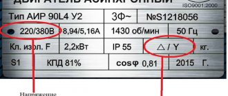
Important! In order to connect a single-phase electric motor to a single-phase network, you need to read the motor data on the tag and know the following:
P = 1.73 * 220 V * 2.0 * 0.67 = 510 (W) calculation for 220 V
P = 1.73 * 380 * 1.16 * 0.67 = 510.9 (W) calculation for 380 V
According to the formula, it becomes clear that electrical power exceeds mechanical power. This is the necessary reserve to compensate for power losses during start-up - the creation of a rotating moment of the magnetic field.
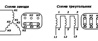
There are two types of winding - star and delta. Based on the information on the motor tag, you can determine which system is used in it.
see also
Comments 31
There was a problem: the casing was closed; there was no airflow to the engine. There is a heat sensor on the engine body.
Mine was “buried” in the wiring of the windings.
put the conder (white barrel) at 50 mF (50 microfarads), it will be both starting and working
Can you explain why the air conditioner needs to be changed? Today I just pulled out the thermal relay from the wiring and secured it closer to the fan - I worked the shift without stopping. Although the engine was already very hot.
if it is very hot, the varnish on the wires will come off and there will be a short circuit inside, and this is an engine replacement :(
Can you explain why the air conditioner needs to be changed? Today I just pulled out the thermal relay from the wiring and secured it closer to the fan - I worked the shift without stopping. Although the engine was already very hot.
when starting, it gives off current like a battery, and when it gives it back, it charges, parallel to the running engine; when the load on the engine increases, it takes on the “extra” current (the one that goes into the engine for “heating” (as the emf decreases, the windings heat up and, as a result, the engine “burns out” (turn-to-turn short circuit). simpler, a thermal relay, but with condensers - more correct operation of the motor (I’m an artist, that’s how I see it;-)) electricians, correct
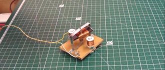
A mobile concrete mixer is a real assistant on a construction site. With its small size, this simple device allows you to obtain the required amount of masonry mortar or concrete of a certain grade in a matter of minutes.
However, a concrete mixer has to work in inhumane conditions: dust, dirt, heat, cold, humidity, precipitation... All this often leads to breakdowns of the unit, which is why labor productivity on the site drops sharply.
One of the most common malfunctions that occur with electric concrete mixers is the failure of the device’s on/off button block.
This problem is very common and manifests itself as follows: when you press the green button, the electric motor starts, but as soon as you release it, the motor “stalls”.
Why does this happen? Everything is very simple. The fact is that the start button of a concrete mixer is not just a button in the classical sense, but a magnetic starter of the KJD17 type.
This is approximately what the diagram of a concrete mixer button looks like:
As can be seen from this diagram, there is a coil inside the starter housing, one of the contacts of which is powered through a thermal relay.
In good condition, it is enough to press the green start button so that the coil holds it in the pressed position.
This coil serves as a kind of fuse that will turn off the unit if the electric motor overheats.
When the motor overheats, the contacts of the thermal relay open, the voltage on the coil disappears, and it stops holding the start button - the concrete mixer shuts down in an emergency. This was done primarily to protect the motor winding from burnout.
This is a star winding circuit
Red arrows are the voltage distribution in the motor windings, indicating that a single phase voltage of 220 V is distributed on one winding, and a linear voltage of 380 V is distributed on the other two windings. Such a motor can be adapted for a single-phase network according to the recommendations on the tag: find out for which windings are created, they can be connected in a star or triangle.
Single-phase capacitor motors of
the AIRE and ADME
are designed to complete household and industrial electric drives - various mechanisms that do not require speed adjustment (woodworking machines, pumps, compressors, concrete mixers, etc.).
Main (basic) version
– asynchronous single-phase capacitor electric motor with two working windings and a small-sized attached working capacitor, designed for operating mode S1, powered by an alternating current network of 50 Hz with a voltage of 220V, climatic version and placement category U3; degree of protection IP54, with typical technical characteristics meeting the requirements of the standards. Engines with the designation AIR. K2 have an additional starting capacitor and are characterized by increased starting torque.
Most often, our houses, plots, and garages are supplied with a single-phase 220 V network. Therefore, equipment and all home-made products are made so that they work from this power source. In this article we will look at how to correctly connect a single-phase motor.
AIRE80S2 electric motor 2.2 kW 2810 rpm (single-phase 220) Elmash Russia
It is carried out from a network with a voltage of 220/230 Volts, alternating current with a frequency of 50 Hz. It is optimal to position the motors in such a way that they are protected from significant temperature changes, since these can have a negative impact on the correct operation of the capacitor. If temperature fluctuations occur, periodic checking of the capacitor is necessary.
The stator windings are made of high-quality copper, coated with varnish in compliance with all necessary technological processes, the main purpose of which is to increase the service life of the stator insulating coating. Single-phase electric motor AIRE80S2 asynchronous capacitor motor, power 2.2 kW, belongs to high-speed motors, rotation speed reaches 3000 rpm . They are equipped with a squirrel cage type rotor.
Connection diagram for a single-phase motor (capacitor)
There are 6 pins located on the terminal block of such a motor; these pins are connected in the following order: U1 and U2 are the main winding, Z1 and Z2 are the auxiliary winding. The dotted area is the working capacitor.
To connect the motor in the reverse direction, you need to apply an alternating voltage ~220 (V) to the same terminals W2 and V1, and place the jumpers as shown in the picture below, i.e. between terminals U1-V1 and W2-U2.
To connect the motor in the forward direction, you need to apply an alternating voltage ~220 (V) to terminals W2 and V1, and place jumpers as shown in the picture below, i.e. between terminals U1-W2 and V1-U2.
If you have a need to purchase this type of equipment, buying a single-phase electric motor AIRE80S2 “ELMASH” with a voltage of 220 Volts will not be a problem. To do this, call 8 (800) 700-30-67 toll-free throughout Russia or place an online order on our website www.agregat.me or write by email. The order will be accepted and processed immediately.
agregat.me
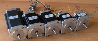
Asynchronous or collector: how to distinguish
In general, you can distinguish the type of engine by the plate - the nameplate - on which its data and type are written. But this is only if it has not been repaired. After all, anything can be under the casing. So if you are not sure, it is better to determine the type yourself.
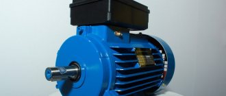
This is what a new single-phase capacitor motor looks like
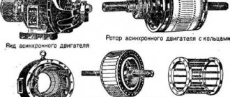
How do collector motors work?
You can distinguish between asynchronous and commutator motors by their structure. The collectors must have brushes. They are located near the collector. Another mandatory attribute of this type of engine is the presence of a copper drum, divided into sections.
Read also: How to remove a stuck terminal from a battery
Such motors are produced only as single-phase ones; they are often installed in household appliances, as they allow one to obtain a large number of revolutions at the start and after acceleration. They are also convenient because they easily allow you to change the direction of rotation - you just need to change the polarity. It is also easy to organize a change in the rotation speed by changing the amplitude of the supply voltage or its cutoff angle. That is why such engines are used in most household and construction equipment.
Commutator motor structure
The disadvantages of commutator motors are high operating noise at high speeds. Remember a drill, an angle grinder, a vacuum cleaner, a washing machine, etc. The noise during their operation is decent. At low speeds, commutator motors are not so noisy (washing machine), but not all tools operate in this mode.
The second unpleasant point is that the presence of brushes and constant friction leads to the need for regular maintenance. If the current collector is not cleaned, contamination with graphite (from brushes being worn out) can cause adjacent sections in the drum to become connected and the motor simply stops working.
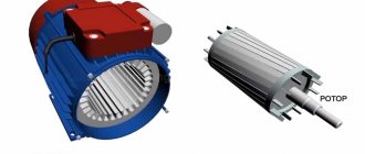
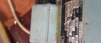
Asynchronous
An asynchronous motor has a starter and a rotor, and can be single or three phase. In this article we consider connecting single-phase motors, so we will only talk about them.
Asynchronous motors are characterized by a low noise level during operation, therefore they are installed in equipment whose operating noise is critical. These are air conditioners, split systems, refrigerators.
Structure of an asynchronous motor
There are two types of single-phase asynchronous motors - bifilar (with a starting winding) and capacitor. The whole difference is that in bifilar single-phase motors the starting winding works only until the motor accelerates. Afterwards it is turned off by a special device - a centrifugal switch or a start-up relay (in refrigerators). This is necessary, since after overclocking it only reduces efficiency.
In capacitor single-phase motors, the capacitor winding runs all the time. Two windings - main and auxiliary - are shifted relative to each other by 90°. Thanks to this, you can change the direction of rotation. The capacitor on such engines is usually attached to the housing and is easy to identify by this feature.
You can more accurately determine the bifolar or capacitor motor in front of you by measuring the windings. If the resistance of the auxiliary winding is less than half (the difference can be even more significant), most likely this is a bifolar motor and this auxiliary winding is a starting winding, which means that a switch or starting relay must be present in the circuit. In capacitor motors, both windings are constantly in operation and connecting a single-phase motor is possible through a regular button, toggle switch, or automatic machine.
How to check the performance of the unit
Before starting assembly, it is necessary to perform a performance check of the engine. To do this, the motor is first turned on and operated for 15 minutes. If the motor housing is very hot, this may be due to:
- bearing tightness;
- severe deterioration of the structure;
- bearing contamination;
- capacitor capacitance is too large.
In this case, the motor must be turned off, the capacitor capacity reduced, or cleaning and repair work performed on the motor, i.e. troubleshoot problems.
Before turning on a single-phase motor, it is important to check its winding.
Before this, it is necessary to determine which winding is being used. Usually two-phase windings are used, which consist of 2 parts:
- starting winding;
- main winding.
Such a system is necessary in order to ensure that the rotor starts to rotate; it is by this value that all single-phase motors can be divided into the following categories:
- single-phase electric motor with a working capacitor;
- motor with starting winding.
Connection diagram for single-phase capacitor motors: a - with working capacitance Cp, b - with working capacitance Cp and starting capacitance Sp.
For example, the unit has 3 outputs, measurements show the following values: 10 Ohm, 25 and 15 Ohm. After the measurements have been taken, it is necessary to determine the network wires for which the readings will be 10 and 15 ohms. In this case, the 10 Ohm wire will be the network wire, and the 15 Ohm wire will be the starting wire, connected through the network.
The type of windings of a single-phase motor can give the following readings: 10, 10 and 20 Ohms. Typically, such an electric motor is used for household washing machines and other equipment intended for the home. Starting and operating windings have the same meaning; they are performed as for three-phase units.
Most often, our houses, plots, and garages are supplied with a single-phase 220 V network. Therefore, equipment and all home-made products are made so that they work from this power source. In this article we will look at how to correctly connect a single-phase motor.
Connection diagrams for single-phase asynchronous motors
With starting winding
To connect a motor with a starting winding, you will need a button in which one of the contacts opens after switching on. These opening contacts will need to be connected to the starting winding. In stores there is such a button - this is PNDS. Its middle contact closes for the holding time, and the two outer ones remain in a closed state.
Appearance of the PNVS button and the state of the contacts after the “start” button is released"
First, using measurements, we determine which winding is working and which is starting. Typically the output from the motor has three or four wires.
Consider the option with three wires. In this case, the two windings are already combined, that is, one of the wires is common. We take a tester and measure the resistance between all three pairs. The working one has the lowest resistance, the average value is the starting winding, and the highest is the common output (the resistance of two windings connected in series is measured).
If there are four pins, they ring in pairs. Find two pairs. The one with less resistance is the working one, the one with more resistance is the starting one. After this, we connect one wire from the starting and working windings, and bring out the common wire. A total of three wires remain (as in the first option):
- one from the working winding is working;
- from the starting winding;
- general.
We work further with these three wires - we use them to connect a single-phase motor.
With all these
- Connecting a single-phase motor with a starting winding via the PNVS button
connecting a single-phase motor
We connect all three wires to the button. It also has three contacts. Be sure to place the starting wire on the middle contact (which closes only during the start), the other two - on the outermost (arbitrary). We connect a power cable (from 220 V) to the extreme input contacts of the PVNS, connect the middle contact with a jumper to the working one (note! not to the common one). That's the whole circuit for switching on a single-phase motor with a starting winding (bifolar) through a button.
Condenser
When connecting a single-phase capacitor motor, there are options: there are three connection diagrams and all with capacitors. Without them, the engine hums, but does not start (if you connect it according to the diagram described above).
Connection diagrams for a single-phase capacitor motor
The first circuit - with a capacitor in the power supply circuit of the starting winding - starts well, but during operation the power it produces is far from rated, but much lower. The connection circuit with a capacitor in the connection circuit of the working winding gives the opposite effect: not very good performance at start-up, but good performance. Accordingly, the first circuit is used in devices with heavy starting (concrete mixers, for example), and with a working condenser - if good performance characteristics are needed.
Circuit with two capacitors
There is a third option for connecting a single-phase motor (asynchronous) - install both capacitors. It turns out something between the options described above. This scheme is implemented most often. It is in the picture above in the middle or in the photo below in more detail. When organizing this circuit, you also need a PNVS type button, which will connect the capacitor only during the start time, until the motor “accelerates”. Then two windings will remain connected, with the auxiliary winding through a capacitor.
Connecting a single-phase motor: circuit with two capacitors - working and starting
When implementing other circuits - with one capacitor - you will need a regular button, machine or toggle switch. Everything connects there simply.
Selection of capacitors
There is a rather complex formula by which you can calculate the required capacity accurately, but it is quite possible to get by with recommendations that are derived from many experiments:
- The working capacitor is taken at the rate of 70-80 uF per 1 kW of engine power;
- starting - 2-3 times more.
The operating voltage of these capacitors should be 1.5 times higher than the network voltage, that is, for a 220 V network we take capacitors with an operating voltage of 330 V and higher. To make starting easier, look for a special capacitor in the starting circuit. They have the words Start or Starting in their markings, but you can also use regular ones.
Operating principle of a commutator motor
The brushed motor, found in washing machines and electric drills, has windings on the stator and rotor.
Brushed motor
The rotor windings are wound in the form of frames and placed in special grooves, and they are switched using collector leads and contacts in the form of graphite brushes.
commutator motor rotor
The rotor structure is designed in such a way that at any moment only one frame is energized, the magnetic field of which is perpendicular to the field of the stator winding.
The electromagnetic interaction of polar magnetic poles tends to rotate the rotor so that the direction of its magnetic field coincides with the stator field, like a compass needle.
But, as soon as the rotor turns to a certain angle, the contacts of the frame come out of contact with the brushes, and the next winding is turned on, and the process is repeated, creating a continuous torque.
Connection to a 220 V network for a commutator motor
The circuit of the commutator electric motor is designed in such a way that the directions of the currents in the rotor stator winding and the rotor frame always coincide, regardless of the phase of the alternating voltage. Due to the coincidence of the direction of the currents, the resulting magnetic fields will always be perpendicular, which will cause the torque of the shaft.
Therefore, it is very important to install a jumper at the motor terminals to connect the stator and rotor windings in series. By swapping the leads of the stator or rotor windings, you can change the direction of rotation of the motor shaft.
connection diagram
To complete the picture, you need to trace the path of the current - one of the terminals from the commutator brush is connected to a 220 V network (let's say phase, but it doesn't matter). The output of the other brush must be connected to one output of the stator using a jumper. The remaining output from the stator is connected to a 220 V network (zero), completing the circuit.
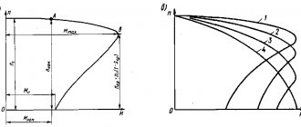
Operating principle of a single-phase asynchronous electric motor
Unlike a commutator motor, in a single-phase asynchronous electric motor with a squirrel-cage rotor at rest,
asynchronous motor device
in which currents are induced, creating a magnetic field that interacts with the electromagnetic field of the coil, the vectors of the resulting forces (M, -M) balance each other. This means that when connected to the network, the motor shaft will not rotate, and an initial torque S is required to start it.
You can spin the shaft by hand and apply mains voltage, then the engine will pick up speed. Many people do this when starting a sharpener, but this method is completely unacceptable if you need to spin the rotating knives of a vegetable cutter or lawn mower.
Since in a three-phase electric motor the rotational torque is specified structurally using the arrangement of the windings and the phase displacement of the three-phase network, in a single-phase motor an additional starting winding is used for starting, thanks to which a rotational torque is created to displace the rotor.
Connection diagram 1
The phase shift of the current of the additional winding relative to the 220 V sinusoid is created using a capacitor.
Connection diagram 2
Connecting an asynchronous single-phase electric motor to the network. On the body of a single-phase asynchronous electric motor there must be a connection diagram, which indicates the terminals of the main and additional windings, as well as the capacitance of the capacitor.
Winding terminals
But, if the circuit is lost somewhere, then you need to determine the working and starting windings by measuring and comparing the resistance - the main one should have less. To do this, you need to take a multimeter, set the measurement range in Ohms, and measure the resistance between the terminals one by one.
Determination of starting and operating windings
Since these windings often have a common terminal, it is determined empirically - the sum of the resistances measured from a given winding wire must correspond to the total resistance of the windings connected in series. If the motor design allows, then the identity of the terminals can be determined visually - the wires of the working winding have a cross-section (thickness ) more.
working and starting windings
The working winding is connected to a voltage of 220 V directly, and the starting winding is connected in series with the capacitor. If the windings are connected inside the motor, then such a circuit will not allow changing the direction of rotation. If four wires come out of the motor from two windings, then the direction of rotation will depend on the choice of leads for connecting them into a common tap.
Motor rotation selection
There are electric motors with identical windings - they are called two-phase.
Single-phase motor modes
Since single-phase and two-phase motors require the use of a capacitor to start, such electric motors are called capacitor motors. There are several modes of operation of a capacitor motor:
- With a starting capacitor and an additional winding, which are connected only for the start time. The capacity is selected based on 70 μF per 1 kW of engine power;
- With a working capacitor with a capacity of 23-35 uF and an additional winding connected all the time;
- With a working and starting capacitor connected in parallel with the working one.
Used in cases where the engine is difficult to start. The capacity of the working capacitor is two to three times less than the starting capacitor rating (70 µF/1 kW).
Due to the complexity of the calculation formulas, it is customary to select containers based on the above proportions. In reality, having connected the electric motor, you need to monitor its operation and heating. If the engine heats up noticeably in mode with a working capacitor, then its capacity must be reduced. You need to select capacitors with an operating voltage of at least 450 V.
The engine with a starting capacitor is started manually using the control button,
or a circuit with two contactors, one of which (starting) does not have self-retaining and is held by the current of a closed push-button contact or time relay. Some capacitor motors have a centrifugal contact, used at start-up, that opens when the speed increases.
Connecting a three-phase motor to a 220 V network
In a similar way, using a capacitor, a three-phase motor is connected in a star or delta circuit.
The capacitance is calculated based on the operating voltage and current,
or rated motor power.
By analogy with a single-phase electric motor, in the case of difficult starting of a three-phase motor, a starting capacitor is used, the capacitance of which is two to three times higher than the operating rating.
When connecting a three-phase electric motor to a 220 V network using a starting capacitor, you need to remember that with such a connection scheme, the motor will not work at full efficiency and will not develop maximum power.
For full operation of such an engine, three phases are needed, which can be obtained by running a 380 V network, or using a complex electronic circuit designed for a specific power, generating a phase shift using powerful power semiconductor switches.
Having many different capacitors, but not finding the desired capacitance value, you can connect them in parallel or in series.
By combining these connection methods, you can get closer to the required capacity rating.
Single-phase capacitor motors of
the AIRE and ADME
are designed to complete household and industrial electric drives - various mechanisms that do not require speed adjustment (woodworking machines, pumps, compressors, concrete mixers, etc.).
Main (basic) version
– asynchronous single-phase capacitor electric motor with two working windings and a small-sized attached working capacitor, designed for operating mode S1, powered by an alternating current network of 50 Hz with a voltage of 220V, climatic version and placement category U3; degree of protection IP54, with typical technical characteristics meeting the requirements of the standards. Motors with the designation AIRE...K2 have an additional starting capacitor and are characterized by an increased starting torque.