What is rotation?
In physics, it is understood as such a movement of a material point around a certain axis, at which its distance to this axis remains constant. This is called the radius of rotation.
You may be interested in:Educational environment of an educational institution: general information, features and requirements
Examples of this movement in nature are the rotation of planets around the Sun and around their own axis. In technology, rotation is represented by the movement of shafts, gears, car or bicycle wheels, and the movement of windmill blades.
How to determine the power of an asynchronous electric motor.
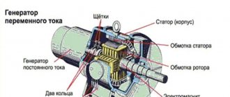
Electric motor - stator winding
From time to time during work, you need to find the number of revolutions of an asynchronous electric motor that does not have a tag. And not every electrician can cope with this task. But my worldview is that every electrician should understand this. At your own workplace, as they say - out of duty, you understand all the properties of your own engines. And they ran to a new workplace, and there were no tags on any of the engines. Finding the number of revolutions of an electric motor is even very simple and straightforward. Determined by winding. To do this, you need to remove the motor cover. It is better to do this with the back cover, since there is no need to remove the pulley or half-coupling. Just remove the cover
cooling and the impeller and motor cover are accessible. After removing the cover, the winding can be seen quite clearly. Find one section and see how many
Engine – 3000 rpm
It occupies space around the circumference of a circle (stator). Now remember, if the coil occupies half a circle (180 degrees) - this is a 3000 rpm engine.
Engine – 1500 rpm
If there are three sections in a circle (120 degrees), this is a 1500 rpm engine. Well, if the stator accommodates four sections (90 degrees) - this engine is 1000 rpm. This is how you can quite simply find the number of revolutions of an “unknown” electric motor. This can be clearly seen in the pictures presented.
Engine – 1000 rpm
This is a way of determining when the winding coils are wound in sections. And there are “loose” windings; you can’t find them this way anymore. This method of winding occurs rarely.
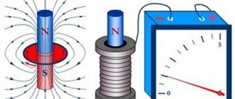
There is another way to determine the number of revolutions. In the rotor of an electric motor, there is a residual magnetic field that can induce a small EMF in the stator winding if we rotate the rotor. This EMF can be “caught” - with a milliammeter. Our task is as follows: it is necessary to find the winding of one phase, regardless of how the windings are connected, a triangle or a star. And we connect a milliammeter to the ends of the winding, rotating the motor shaft, see how many times the milliammeter needle deflects per revolution of the rotor, and use this table to see what kind of engine you are determining.
(2p) 2 3000 r/min (2p) 4 1500 r/min (2p) 6 1000 r/min (2p) 8 750 r/min
These are the simple and I think understandable two ways to determine the number of revolutions on which there is no tag (plate).
The PM10-R device was produced in the USSR, maybe someone still has it. For those who have not seen or knew about such a meter, I suggest you look at a photo of your own. The set includes two nozzles, one for measuring revolutions along the shaft axis and a second one for measuring along the circumference of the shaft.
You can also measure the number of revolutions using a “Digital Laser Tachometer”
“Digital laser tachometer”
Technical properties:
Spectrum: 2.5rpm ~ 99999rpm Resolution/step: 0.1rpm for spectrum 2.5~999.9rpm, 1rpm 1000rpm and more Accuracy: +/ – 0.05% Working distance: 50mm ~ 500mm The smallest and largest values are also indicated For those who really need it, it’s just a super thing! L. Ryzhenkov
Physical quantities describing rotation
For the numerical description of rotation in physics, a number of characteristics were introduced. Let's list them and characterize them.
First of all, this is the angle of rotation, denoted by θ. Since a complete circle is characterized by a central angle of 2*pi radians, then, knowing the amount θ by which the rotating body turned over a certain period of time, we can determine the number of revolutions during this time. In addition, the angle θ allows you to calculate the linear path traversed by the body along the curved circle. The corresponding formulas for the number of revolutions n and the distance traveled L have the form:
n = θ/(2*pi);
L = θ*r.
Where r is the radius of the circle or radius of rotation.
The next characteristic of the type of movement under consideration is angular velocity. It is usually denoted by the letter ω. It is measured in radians per second, that is, it shows the angle in radians through which a rotating body turns in one second. For the angular velocity in the case of uniform rotation, the formula is valid:
ω = θ/t
DC motors
In addition to AC machines, there are electric motors connected to a DC network. The speed of such devices is calculated using completely different formulas.
Rated rotation speed
The speed of a DC machine is calculated using the formula in the figure below, where:
- n – number of revolutions per minute,
- U – network voltage,
- Rya and Iya – armature resistance and current,
- Ce – motor constant (depending on the type of electric machine),
- Ф – stator magnetic field.
These data correspond to the nominal values of the parameters of the electric machine, the voltage on the field winding and the armature or the torque on the motor shaft. Changing them allows you to adjust the rotation speed. It is very difficult to determine the magnetic flux in a real motor, so calculations are made using the current flowing through the field winding or armature voltage.
The speed of commutator AC motors can be found using the same formula.
Speed adjustment
Adjustment of the speed of an electric motor operating from a DC network is possible within a wide range. It is possible in two ranges:
- Up from nominal. To do this, the magnetic flux is reduced using additional resistances or a voltage regulator;
- Down from par. To do this, it is necessary to reduce the voltage on the armature of the electric motor or connect a resistance in series with it. In addition to reducing the speed, this is done when starting the electric motor.
Knowing what formulas are used to calculate the rotation speed of an electric motor is necessary when designing and setting up equipment.
Angular frequency, period and angular velocity
It was already noted above that an important property of any rotational movement is the time during which one revolution is completed. This time is called the rotation period. It is designated by the letter T and measured in seconds. The formula for period T can be written in terms of angular velocity ω. The corresponding expression looks like:
T = 2*pi/ω
The reciprocal of the period is called frequency. It is measured in hertz (Hz). For circular motion, it is convenient to use not the frequency itself, but its angular analogue. Let's denote it f. The formula for angular rotation frequency f is:
f = 2*pi/T
To calculate the angular frequency, you need to know the period of rotational motion.
Comparing the last two formulas, we arrive at the following equality:
f = ω
This equality means the following:
- the formulas for angular frequency and angular velocity coincide, therefore these quantities are numerically equal to each other;
- Like speed, frequency shows how much angle in radians a body rotates in one second.
The only difference between these quantities is: angular frequency is a scalar quantity, while speed is a vector.
Adjusting the speed
Working with a variety of electrical tools and equipment at home or at work certainly raises the question of how to regulate the speed of the electric motor. For example, it becomes necessary to change the speed of movement of parts in a machine or on a conveyor, adjust the performance of pumps, reduce or increase air flow in ventilation systems.
It is almost pointless to carry out these procedures by lowering the voltage; the speed will drop sharply and the power of the device will significantly decrease. Therefore, special devices are used to adjust engine speed. Let's look at them in more detail.
The microcontroller controls the entire operation of the converter
Thanks to this approach, it becomes possible to achieve a smooth increase in engine speed, which is extremely important in mechanisms with heavy loads. Slow acceleration reduces loads, positively affecting the service life of industrial and household equipment
All converters are equipped with several levels of protection. Some models operate using a single-phase voltage of 220 V. The question arises: is it possible to make a three-phase motor rotate thanks to one phase? The answer will be positive if one condition is met.
When applying single-phase voltage to the winding, it is necessary to “push” the rotor, since it itself will not budge. For this you need a starting capacitor. After the engine starts rotating, the remaining windings will provide the missing voltage.
A significant disadvantage of this scheme is considered to be a strong phase imbalance. However, it is easily compensated for by including an autotransformer in the circuit. Overall, this is a rather complex scheme. The advantage of a frequency converter is the ability to connect asynchronous motors without the use of complex circuits.
Linear rotation speed, frequency and angular frequency
In technology, for some rotating structures, for example, gears and shafts, their operating frequencies μ and linear speeds v are known. However, each of these characteristics can be used to determine the angular or cyclic frequency.
It was noted above that the frequency μ is measured in hertz. It shows the number of revolutions of a rotating body in one second. The formula for it takes the form:
μ = 1/T
If we compare this expression with the corresponding equality for f, then the formula for finding the rotation frequency f through μ describing it will look like:
f = 2*pi*μ
This formula is intuitive because μ shows the number of revolutions per unit of time, and f reflects the same value, only represented in radians.
Linear speed v is related to angular speed ω by the following equality:
v = ω*r
Since the absolute values of f and ω are equal, it is easy to obtain the corresponding formula for the cyclic rotation frequency from the last expression. Let's write it down:
f = v/r
Where r is the radius of rotation. Note that the speed v increases linearly with increasing radius r, and the ratio of these quantities is a constant. The last conclusion means that if you measure the cyclic frequency of rotation at any point in the cross section of a rotating massive object, then it will be the same everywhere.
Why do you need to know engine power?
Of all the technical characteristics of an electric motor (efficiency, rated operating current, speed, etc.), the most significant is power. Knowing the main data, you can:
- Select a thermal relay and automatic circuit breaker with suitable ratings.
- Determine the throughput and cross-section of electrical cables for connecting the unit.
- Operate the engine according to its parameters, avoiding overload.
We described how to measure the power of an electric motor in different ways. Use the one that is optimal in your case. Using any of the methods, you will select a unit that will best meet your requirements. But the most effective option, saving your time and eliminating the need to search for information and carry out measurements and calculations, is to keep the technical passport in a safe place and make sure that the data plate is not lost.
When you receive an electric motor for repair with a missing plate, you have to determine the power and speed by the stator winding. First of all, you need to determine the speed of the electric motor. The easiest way to determine the speed in a single-layer winding is to count the number of coils (coil groups).
| Number of coils (coil groups) in the winding pcs. | Rotation speed rpm. At mains frequency f=50Hz. | ||
| Three-phase | Single-phase in working winding | ||
| Single word | Two-word | ||
| 6 | 6 | 2 | 3000 |
| 6 | 12 | 4 | 1500 |
| 9 | 18 | 6 | 1000 |
| 12 | 24 | 8 | 750 |
| 15 | 30 | 10 | 600 |
| 18 | 36 | 12 | 500 |
| 21 | 42 | 14 | 428 |
| 24 | 48 | 16 | 375 |
| 27 | 54 | 18 | 333 |
| 30 | 60 | 20 | 300 |
| 36 | 72 | 24 | 250 |
According to the table, single-layer windings have 3000 and 1500 rpm. the same number of coils, 6 each, you can visually distinguish them by their step. If a line is drawn from one side of the coil to the other side, and the line passes through the center of the stator, then this is a 3000 rpm winding. drawing No. 1. Electric motors have a 1500 rpm step less.
| 2p | 2 | 4 | 6 | 8 | 10 | 12 |
| rpm f=50Hz | 3000 | 1500 | 1000 | 750 | 600 | 500 |
| 2p | 14 | 16 | 18 | 20 | 22 | 24 |
| rpm f=50Hz | 428 | 375 | 333 | 300 | 272 | 250 |
| 2p | 26 | 28 | 30 | 32 | 34 | 36 |
| rpm f=50Hz | 230 | 214 | 200 | 187,5 | 176,4 | 166,6 |
| 2p | 38 | 40 | 42 | 44 | 46 | 48 |
| rpm f=50Hz | 157,8 | 150 | 142,8 | 136,3 | 130,4 | 125 |
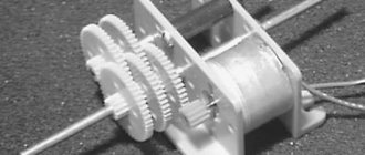
Electric motors as part of gearmotors.
Electric motors have long been included in various gearmotors.
They find their application in both three-stage type MTs3U and two-stage type MTs2U. Electric motors have almost 90% efficiency and do not require constant maintenance. An important parameter is the exceptional environmental friendliness of the electric motor; there are no harmful emissions at all, which makes it indispensable for indoor installation. In short, electric motors are currently recognized as 3 or even 4 times more efficient than traditional internal combustion engines. But sometimes, in the event of an electric motor failure, the buyer finds out that absolutely no accompanying documentation is attached to it. Marking nameplates, even if they have been preserved, may be in a worn-out, shabby state, so that it is simply impossible to see anything on them. How, then, can you determine the engine power and its speed? Here are some step-by-step tips to help you do this.
It should be borne in mind that the number of revolutions refers to the so-called asynchronous speed. Synchronous speed is the speed of rotation of the magnetic field. Asynchronous speed is slightly lower than synchronous due to the presence of mass in the rotating element, as well as the influence of friction forces, which can significantly reduce the efficiency of the motor. However, in practice these differences are almost never of decisive importance.
There are currently 3 main categories of asynchronous electric motors on the market. The first category of the catalog is motors operating at 1000 rpm. In practice, this number is about 950-970 revolutions, but for clarity, it is still rounded to the nearest thousand. The second category is motors producing 1500 rpm. This is also rounded as the actual range is 1430-1470. The third is 3000 rpm. Although in reality such a motor produces 2900-2970 rotations.
How to change the engine speed?
You can change the speed of the rotating moment of the equipment mechanism in various ways, for example, mechanical gearboxes with gear shifts, clutches and other devices. But this is not always possible. In practice, 7 methods are used to correct the rotation speed of variable speed drives. All methods are divided into two main directions.
- Correction of the magnetic field by influencing the frequency of the current, reducing or increasing the number of pole pairs, voltage correction. The direction is typical for motors with a squirrel-cage (SC) rotor.
- Slip is corrected by supply voltage, adding another resistor to the rotor circuit circuit, installing dual supply, or using a cascade of valves. This direction is used for rotors with phases.
- Frequency generators come with two types of control: scalar and vector. With scalar control, the device operates at certain values of the output potential difference and frequency; they work in primitive household appliances, for example, fans. With vector control, the current strength is set quite accurately.
- When choosing a device, power parameters play a decisive role. The amount of power expands the scope of use and simplifies maintenance.
- When choosing a device, the operating voltage range of the network is taken into account, which reduces the risk of its failure due to sudden changes in potential difference. If the voltage increases excessively, the network capacitors may explode.
- Frequency is an important factor. Its value is determined by production requirements. The lowest value indicates the possibility of using the speed in the optimal operating mode. To obtain a larger frequency range, frequency generators with vector control are used. In reality, inverters with a frequency range of 10 to 10 Hz are often used.
- A frequency converter that has many different outputs and inputs is convenient to use, but its cost is higher and configuration is more difficult. There are three types of frequency connectors: analog, discrete, digital. Reverse communication of input commands is carried out through analog connectors. Digital terminals input signals from digital type sensors.
- When choosing a frequency converter model, you need to evaluate the control bus. Its characteristics are matched to the inverter circuit, which determines the number of pads. The best choice is a frequency generator with a reserve number of connectors for further modernization of the device.
- Frequency drivers that can withstand heavy overloads (15% higher than the motor power) have preferences when choosing. To avoid making mistakes when purchasing a frequency converter, read the instructions. It contains the main parameters for operating the equipment. If you need a device for maximum loads, then you need to choose a frequency converter that keeps the current at peak operation higher than 10% of the nominal value.
Practical measurements
The most accessible way is to check the readings of your household electricity meter. First, you should turn off absolutely all household appliances and turn off the lights in all rooms, since even a burning 40W light bulb will distort the readings. Make sure that the counter does not spin or the indicator does not blink (depending on its model). You are lucky if you have a Mercury meter - it shows the load value in kW, so you only need to turn on the engine for 5 minutes at full power and check the readings.
Induction meters record in kW/h. Record the readings before turning on the engine, let it run for exactly 10 minutes (it is better to use a stopwatch). Take new meter readings and find out the difference by subtraction. Multiply this figure by 6. The resulting result displays the engine power in kW.
If the engine is low-power, calculating the parameters will be somewhat more difficult. Find out how many revolutions (or pulses) are equal to 1 kW/h - you will find the information on the meter. Let's say it's 1600 rpm (or indicator flashes). If the meter makes 20 revolutions per minute when the engine is running, multiply this figure by 60 (the number of minutes in an hour). This turns out to be 1200 rpm. Divide 1600 by 1200 (1.3) - this is the engine power. The result is more accurate the longer you measure the readings, but a small error is still present.
Electric motors as part of gearmotors.
Electric motors have long been included in various gearmotors. They find their application in three-stage MTs3U type. and in two-stage type MTs2U. Electric motors have almost 90% efficiency and do not require constant maintenance. An important parameter is the exceptional environmental friendliness of the electric motor; there are no harmful emissions at all, which makes it indispensable for indoor installation. In short, electric motors are currently recognized as 3 or even 4 times more efficient than traditional internal combustion engines.
But sometimes, in the event of an electric motor failure, the buyer finds out that absolutely no accompanying documentation is attached to it. Marking nameplates, even if they have been preserved, may be in a worn-out, shabby state, so that it is simply impossible to see anything on them. How, then, can you determine the engine power and its speed? Here are some step-by-step tips to help you do this.
It should be borne in mind that the number of revolutions refers to the so-called asynchronous speed. Synchronous speed is the speed of rotation of the magnetic field. Asynchronous speed is slightly lower than synchronous due to the presence of mass in the rotating element, as well as the influence of friction forces, which can significantly reduce the efficiency of the motor. However, in practice these differences are almost never of decisive importance.
There are currently 3 main categories of asynchronous electric motors on the market. The first category of the catalog is motors operating at 1000 rpm. In practice, this number is about 950-970 revolutions, but for clarity, it is still rounded to the nearest thousand. The second category is motors producing 1500 rpm. This is also rounded as the actual range is 1430-1470. The third is 3000 rpm. Although in reality such a motor produces 2900-2970 rotations.