Proper placement of surge suppressors in the power supply line is fundamental to the correct operation of the designed surge protection system.
As noted earlier, when organizing surge protection systems for power electrical equipment, limiters are mounted in the following places:
- outside the construction site, in lightning protection zone 0B, at the entrance of power cables to devices (usually class II limiters, sometimes class I);
- at the point where power cables pass through the building wall (depending on the level of threat, these are class I or II limiters) - in a cable connection, grounded along the shortest path to a grounding device;
- inside the construction site:
- in local distribution boards (depending on the level of threat, these are class II or III limiters);
- close to the protected devices (usually class III limiters, sometimes class II, from the point of view of the too small rated current of class III limiters, which is most often 16 A).
It must be emphasized here that of all the locations for surge suppressors suggested in section 443 of IEC 60364-4, the only correct location is in a cable connection, provided that the connection is in the wall of the building being protected.
The code-recommended placement of limiters in overhead lines or building equipment is not practical for facility protection.
Placement of limiters in the overhead line:
In the case of placing limiters in an overhead line, we must not forget about the possibility of overvoltage shocks penetrating the power cable along the “overhead line pole - building” route, which makes this placement useless.
Placement of limiters inside the building:
The full version of the article is available only to registered users!
Get access to all materials on the site completely free of charge!
Purpose and principle of operation of surge arresters
Nonlinear surge suppressors (SSRs) are high-voltage devices widely used in industry, used in networks of medium and high AC voltage classes.
Nonlinear limiters protect the insulation of substation electrical equipment and electrical networks from surges in switching and atmospheric overvoltages. The limiters are designed for operation at temperatures from – 60°С to + 45°С (for indoor installation the maximum temperature is + 55°С) and up to 1000 meters above sea level.
The protective function of the surge arrester is that during the nominal operation of the electrical installation, the current through the surge suppressor is negligible - fractions of a milliampere. If a pulse voltage surge occurs, the resistance of the limiter instantly drops to a few ohms, while the varistors go into a conducting state and limit the further increase in overvoltage, converting the pulse energy into thermal energy, which is dissipated into the environment. The limiter returns to a non-conducting state after the end of the overvoltage wave. An arrester can effectively limit high-frequency surge voltages by instantly transitioning to a conducting state.
Figure 1 – Graph of changes in voltage on the equipment and current through the arrester when exposed to overvoltages.
The need for surge protection
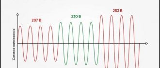
To avoid peak values, specialized devices have been developed - overvoltage limiters.
Pulse overvoltage is a sharp increase in the potential difference in the network, exceeding the maximum operating voltage limit. The jump is short - up to 1 nanosecond (1•10-9 sec.), so conventional ultrasonic devices may not have time to operate and pass the pulse into the internal power grid. The amplitude can be 10 times greater than the nominal amplitude.
Origin:
- atmospheric (thunderstorm) - caused by lightning with an average current strength of 200 kA hitting the lightning rod of a house or objects near it (the current goes into the ground, but an EMF appears in the wiring of the house);
- switching - malfunctions or replacement of switching equipment/circuit sections, startup of powerful electrical equipment, failure of a transformer.
Regardless of the nature of the occurrence, such problems carry a risk for all connected devices: fire of wiring insulation (designed for 1-1.5 kV), damage to the electrical circuits of the devices and their complete unsuitability for repair.
Designation of surge arresters in the diagrams. Connection diagrams
The standard graphic designation of an arrester circuit element is shown in Figure 2.
Figure 2 – Graphic designation of surge arrester
Figure 3 – Connection diagram for surge arresters to protect industrial and residential consumers.
Figure 4 – Protection of a 10 kV switchgear from incoming lightning waves with a 10 kV overhead line on wooden supports.
How to connect an SPD in a private house?
SPD installation is carried out depending on the voltage indicator: 220V (one phase) and 380V (three phases).
The connection scheme can be aimed at continuity or security; priorities need to be determined. In the first case, lightning protection may be temporarily turned off in order to prevent interruptions in supply to consumers. In the second case, it is unacceptable to turn off the lightning protection, even for a few seconds, but a complete shutdown of the supply is possible.
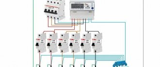
Connection diagram in a single-phase network of the TN-S grounding system
When using a single-phase TN-S network, the phase, neutral working and neutral protective conductors must be connected to the SPD. Phase and zero are first connected to the corresponding terminals, and then via a loop to the equipment line. The grounding conductor is connected to the protective conductor. The SPD is installed immediately after the introductory circuit breaker. To facilitate the connection process, all contacts on the device are marked, so no difficulties should arise.
Explanation of the diagram: A, B, C – phases of the electrical network, N – working neutral conductor, PE – protective neutral conductor.
Connection diagram in a three-phase network of the TN-S grounding system
A distinctive feature of a three-phase TN-S network from a single-phase one is that five conductors, three phases, a working neutral and a protective neutral conductor come from the power source. Three phases and a neutral wire are connected to the terminals. The fifth protective conductor is connected to the body of the electrical device and the ground, that is, it serves as a kind of jumper.
Connection diagram in a three-phase network of the TN-C grounding system
In the TN-C grounding system, the working and protective conductors are combined into one wire (PEN), this is the main difference from the TN-S grounding.
How to choose a voltage stabilizer for a private house or apartment?
The TN-C system is simpler and already quite outdated, and is common in outdated housing stock. According to modern standards, the TN-CS grounding system is used, in which the neutral working and neutral protective conductors are located separately.
Switching to a newer system is necessary in order to avoid electric shock to operating personnel and fire situations. And of course, the TN-CS system has better protection against sudden surge voltages.
In all three connection options, in the event of an overvoltage, the current is directed to the ground through a grounding cable or through a common protective wire, which prevents the impulse from harming the entire line and equipment.
Surge arrester type KR, RT, RV, RK
Overvoltage surge protectors-KR are designed to protect electrical equipment in networks from 6 to 10 kV. Recommended for the protection of transformers and motors.
Surge surge protectors-RT are recommended for protecting critical electrical equipment in networks from 3 to 10 kV with frequent exposure to overvoltages. Used to protect transformers of electric arc furnaces, electric generators, etc.
Surge arresters-RV are recommended for use instead of valve arresters of the RVO series. SPD-RV type limiters do not require preliminary calculations, since they are designed against overvoltages during single-phase arc faults.
OPN-RK are intended for operation in areas of 1-3 degrees of atmospheric pollution, used in networks of 35-110 kV. Designed specifically to protect the neutral insulation of 110 kV transformers.
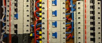
What to use in front of the SPD - circuit breakers or fuses
To continuously supply the room with energy, it is recommended to connect a circuit breaker that will turn off the SPD.
After being struck by lightning
The connection of this machine is also determined by the fact that during the period of pulse withdrawal, what is said to be an accompanying current is formed.
But it is much easier to purchase modular fuses. It is recommended to select a GG type device.
They can protect the entire range of overcurrents. Even if the current has increased slightly, a fuse of this type will still turn it off.
Surge arrester design
Limiters of types KR, RT and VR are high-voltage devices consisting of series-connected varistors located inside an insulating housing. The safe presence of surge arresters under voltage is ensured by the highly nonlinear current-voltage characteristic of varistors. When producing limiters of voltage classes 3-10 kV, a column of resistors is located between metal electrodes and is pressed into a shell made of a special weather-resistant polymer. Limiters of the RK type consist of blocks of varistors connected in series, located inside the tire. The tire consists of a fiberglass cylinder.
SPD: features of selection and application
Even short-term impulse voltage surges, several times higher than the nominal voltage, can cause irreparable damage to expensive electrical equipment and electronics, or even cause a fire. Overvoltage in networks can occur due to thunderstorms, accidents or transients. For example, pulse overvoltages can result from lightning hitting a lightning protection system or power line, switching powerful inductive consumers such as electric motors and transformers, or short circuits.
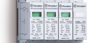
A standard B or C (possibly B+C) arrester consists of two components:
- Limiter base
- Replaceable insert with protective element
The basis
The base of the protective device is mounted on a TS35 DIN rail. It has two clamps. Connect the phase (L) or neutral (N) wire, which may have too much electrical potential. On the other side, connect the PE protective conductor, which is connected to the protective line of the switchgear.
The protective conductor should have a minimum cross-section of 4 mm2, but it wouldn't hurt to go larger. After all, there is a possibility that a very high current will flow.
There are 3 contacts under the PE terminal. As standard, the kit includes a plug that is inserted into the right place and allows you to connect the wires. Thanks to these clips, it is possible to remotely notify in case of damage to the insert or its burnout. This signal can be connected, for example, to the input of the alarm control unit (see diagram). In this case, the control panel will be informed that the insert is damaged by opening the electrical circuit between the red and green wires.
Insert
The insert contains all the most important elements thanks to which the defender functions correctly:
- Class B (Type I) - the main element is simply the spark gap.
- Class C (type II) - here the varistor part is the main element.
Selection of arrester
When choosing an arrester for a particular case, it is necessary to apply the official recommendations of international standards or guidelines (IEC 60099-5). The limiter parameters are selected based on the purpose, installation location, required level of overvoltage limitation, network diagram and its parameters (neutral grounding method, maximum operating voltage of the network, degree of compensation of capacitive current to the ground and its magnitude, etc.).
For their intended purpose, limiters are used to protect equipment from lightning and switching overvoltages. The installation locations, as well as the distances from the protected equipment to the limiters, must comply with the requirements of the “Rules for Electrical Installations”, section 4, seventh edition of the PUE.
Three-phase installation
In a three-phase circuit, the width of the limiter and the number of protected connections increase. However, the operating principle of the limiter remains unchanged. The most commonly used three-layer system protective devices operate in a 4 + 0 system, which means connecting the following lines to the arrester:
- 3 phase wires
- 1 neutral wire
Each of the wires to be protected has equal rights, that is, possible overvoltages are eliminated by supplying current to the protective installation and, as a result, to the ground.
Of course, for TN-C installations (installations without a separate protective conductor) it is possible to purchase protective devices with only 3 protected connectors. Then, from the bottom side, connect the limiter to the PEN (protection neutral) strip.
Technical characteristics of arrester
Table 1 – Technical characteristics of surge arresters type 6 – 10 kV (OPN-KR/TEL–X/X UHL1(2)10/11.5)
| Name of parameters | 6/6.0 | 6/6.9 | 10/10.5 | 10/11.5 | 10/12 |
| Network voltage class, kV | 6 | 6 | 10 | 10 | 10 |
| The highest long-term permissible operating voltage Und; kV | 6.0 | 6.9 | 10.5 | 11.5 | 12.0 |
| Rated discharge current 8/20 μs, In; kA | 10 | 10 | 10 | 10 | 10 |
| Residual voltage Ures; kV; no more: | |||||
| – with a switching current pulse | |||||
| 125 A 30/60µs | 14.3 | 16.2 | 24.8 | 26.9 | 29.7 |
| 250 A 30/60µs | 14.6 | 16.5 | 25.4 | 27.6 | 30.4 |
| 500 A 30/60µs | 15.0 | 17.5 | 26.1 | 28.3 | 31.3 |
| – during a lightning current pulse | |||||
| 5000 A, 8/20µs | 17.7 | 20.0 | 30.7 | 33.3 | 36.9 |
| 10000 A, 8/20μs | 19.0 | 21.5 | 33.0 | 35.8 | 39.6 |
| 20000 A, 8/20μs | 21.2 | 24.0 | 36.7 | 39.9 | 44.1 |
| with a steep current pulse of 10000A, 1/10μs | 21.3 | 24.1 | 36.9 | 40.1 | 44.3 |
| Capacitive conduction current Iс, mA, no more: | |||||
| amplitude | 0.6 | 0.6 | 0.6 | 0.6 | 0.6 |
| effective value | 0.45 | 0.45 | 0.45 | 0.45 | 0.45 |
| Specific energy of surge arrester, kJ/kV Und, not less | 3.6 | 3.6 | 3.6 | 3.6 | 3.6 |
| Maximum current pulse amplitude 4/10 μs, kA | 100 | 100 | 100 | 100 | 100 |
| Explosion-proof short-circuit current Isk, kA | 16 | 16 | 16 | 16 | 16 |
| Maximum bending force, N | 305 | 305 | 305 | 305 | 305 |
The characteristics of surge arresters presented in Figures 5 and 6 were obtained for limiters manufactured by TEL. The “voltage-time” characteristics of 6 - 10 kV limiters of the surge arrester-KR type during the formation of quasi-stationary overvoltages is shown in Figure 5.
Figure 5 – Voltage-time characteristic: 1 – with a preliminary load of 3.6 kJ/kV Und; 2 - without preliminary energy loading.
Table 2 – Technical characteristics of surge arresters type 35 – 110 – 220 kV (OSN/TEL–X/X–550 UHL1)
| Name of parameters | 35/40.5 | 110/78 | 110/84 | 220/146 | 220/156 | 220/168 |
| Network voltage class, kV | 35 | 110 | 110 | 220 | 220 | 220 |
| The highest long-term permissible operating voltage Und; kV | 40.5 | 78 | 84 | 146 | 156 | 168 |
| Rated discharge current 8/20 μs, In; kA | 10 | 10 | 10 | 10 | 10 | 10 |
| Residual voltage Ures; kV; no more: | ||||||
| – with a switching current pulse | ||||||
| 125 A 30/60µs | 93 | 178 | 191 | 334 | 356 | 386 |
| 250 A 30/60µs | 98 | 188 | 202 | 352 | 376 | 404 |
| 500 A 30/60µs | 101 | 192 | 207 | 362 | 384 | 414 |
| – during a lightning current pulse | ||||||
| 5000 A, 8/20µs | 119 | 230 | 247 | 428 | 460 | 494 |
| 10000 A, 8/20μs | 130 | 250 | 269 | 468 | 500 | 538 |
| 20000 A, 8/20μs | 146 | 295 | 301 | 524 | 560 | 602 |
| with a steep current pulse of 10000A, 1/10μs | 153 | 295 | 317 | 552 | 590 | 634 |
| Capacitive conduction current Iс, mA, no more: | ||||||
| amplitude | 0.9 | 0.9 | 0.9 | 0.9 | 0.9 | 0.9 |
| effective value | 0.7 | 0.7 | 0.7 | 0.7 | 0.7 | 0.7 |
| Specific energy of surge arrester, kJ/kV Und, not less | 5.5 | 5.5 | 5.5 | 5.5 | 5.5 | 5.5 |
| Maximum current pulse amplitude 4/10 μs, kA | 100 | 100 | 100 | 100 | 100 | 100 |
| Explosion-proof short-circuit current Isk, kA | 30 | 30 | 30 | 30 | 30 | 30 |
| Maximum bending force, N | 580 | 600 | 600 | 640 | 640 | 640 |
The “voltage-time” characteristics of 35 – 220 kV limiters of type OPN-35,110,220 during the formation of quasi-stationary overvoltages are shown in Figure - 6.
Figure 6 – Voltage-time characteristic: 1 - with preliminary energy dissipation of 5.5 kJ/kV Und; 2 - without preliminary energy dissipation
Appearance and dimensions of surge arresters 6-750 kV
Suspended limiters for voltage classes 6-35 kV are shown in Figure 7.
Figure 7 – suspended surge arrester: a) 6 kV surge arrester; b) surge arrester 10 kV; c) surge arrester 35 kV
The appearance and dimensions of the 110-220 kV suspended surge arrester are shown in Figure 8.
Figure 8 – suspended surge arrester: a) 110 kV surge arrester; b) surge arrester 220 kV
The appearance and dimensions of surge arresters 330-750 kV are presented in Figures 9 and 10.
Figure 9 – a) surge arrester 330 kV; b) surge arrester 500 kV
Figure 10 – 750kV surge arrester
GOST OPN
1. GOST R 52725-2007. Nonlinear surge suppressors for AC electrical installations with voltages from 3 to 750 kV. General technical conditions.
2. GOST R 53735.5-2009 Valve arresters and nonlinear surge suppressors for alternating current electrical installations for voltages from 3 to 750 kV. Part 5. Recommendations for selection and application.
3. GOST 34204-2017 Nonlinear surge suppressors for railway traction networks. General technical conditions.
4. Rules for electrical installations.