An electrical diagram is a document in which, according to GOST rules, connections between the component parts of devices operating due to the flow of electricity are indicated. As you understand, this drawing gives electricians an understanding of how the installation works and what elements it consists of. The main purpose of the electrical diagram is to help in connecting installations, as well as troubleshooting in the circuit.
First, you need to understand what is meant by types and what is meant by types of documents. So, according to GOST 2.701-84, there are the following types of circuits (brief designation in brackets):
- Electrical (E).
- Hydraulic (G).
- Pneumatic (P).
- Gas (X).
- Kinematic (K).
- Vacuum (B).
- Optical (L).
- Energy (P).
- Divisions (E).
- Combined (C).
As for the types, the main ones are:
- Structural (1).
- Functional (2).
- Fundamental (complete) (3).
- Connections (installation) (4).
- Connections (5).
- General (6).
- Location (7).
- United (8).
Based on the indicated designations, you can understand its type and type by the name of the electrical circuit.
Next, we will consider in detail the purpose and composition of each of the listed types of electrical circuits. Before doing this, we recommend that you familiarize yourself with the standard symbols on the diagrams to make it even easier to understand what each version of the drawing is.
Types of electrical circuits
1.1. Structural scheme
This type of document is the simplest and gives an understanding of how the electrical installation works and what it consists of. A graphical representation of all circuit elements allows you to initially see the overall picture in order to move on to a more complex connection or repair process. The reading order is indicated by arrows and explanatory inscriptions, which allows even a novice electrician to understand the structural electrical diagram. You can see the principle of construction in the example below:
Figure 1 — Block diagram
1.2. Functional diagram
The functional electrical diagram of the installation, in fact, is not too different from the structural one. The only difference is a more detailed description of all the components of the chain. This document looks like this:
Figure 2 - Functional diagram
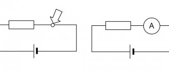
1.3. Schematic diagram
The electrical circuit diagram is most often used in distribution networks, because gives the most comprehensive explanation of how the electrical equipment in question works. Such a drawing must necessarily indicate all the functional components of the circuit and the type of connection between them. In turn, the circuit diagram can have two varieties: single-line (Figure 3) or complete (Figure 4). In the first case, only primary networks, also called power networks, are shown in the drawing. An example of a single line image can be seen below:
Figure 3 - Single line circuit diagram
A complete circuit diagram can be expanded or elemental. If the electrical installation is simple and all the explanations can be put on one main drawing, it is enough to make a detailed plan. If you are dealing with complex equipment that includes a control, automation and measurement circuit, it is better to separate all the individual components into different sheets so as not to get confused.
Figure 4 - Complete circuit diagram
There is also a schematic diagram of the product. This type of document is a kind of copy from the general plan, which only indicates how a certain unit works and what it consists of.
1.4. Wiring diagram
We most often use this type of electrical diagram when we talk about how to install electrical wiring yourself. The fact is that the wiring diagram can show the exact location of all the elements of the circuit, the method of connecting them, as well as the alphanumeric characteristics of the installations that make up the drawing. If we take Figure 5 as an example of the electrical wiring diagram in a one-room apartment, we will see where we need to place sockets, switches, lamps and other products.
Figure 5 - Wiring diagram
The main purpose of a wiring diagram is to provide a guide for electrical work. According to the prepared drawing, you can understand where, what and how to connect.
1.5. Combined scheme
Well, the last electrical circuit used in distribution networks is the combined Figure 6, which can include several types and types of documents. It is used if it is possible to indicate all the important features of the circuit without too much cluttering of the drawing. The integrated project is used most often in enterprises. Home craftsmen are unlikely to encounter this type of scheme. You can see an example below:
Figure 6 - Integrated scheme
How to draw up diagrams in coursework: general requirements
How are schemes drawn up in coursework? First of all, the following requirements must be properly observed:
- Remember that all diagrams must be drawn up in the same style. Otherwise, the inspector may suspect that the student downloaded graphic images for the coursework on a third-party resource and did not create them himself.
- Use the same font for diagrams as throughout the entire work. As a rule, this is Times New Roman. You can change the font size. It can be from 10 to 14.
- Present information in a diagram logically and consistently. The main criterion that a student completed the diagram correctly is the absence of additional questions to the diagram.
- Try not to complicate things. Schemes must be convincing and visual. So build even the most complex schematic images using simple and understandable logic.
- Place more emphasis on the content rather than the appearance of the diagram. It’s better to spend time choosing the right words than the external beauty of semantic blocks.
- Remember how to sign the diagram in the coursework: all inscriptions are made clear, as are the main lines and boundaries of the blocks.
- Check the inscriptions in the diagram and the signatures below for errors. Grammatical and punctuation inaccuracies can spoil the overall impression of the work and affect the final grade.
The basic requirements and rules for the design of schemes in coursework are established and described in GOST 7.32-2017.
Symbols on electrical diagrams
All elements in the diagrams are depicted by conventional graphic symbols, the design and dimensions of which are established in the ESKD standards (GOST 2.721-74 ... GOST 2.796-81).
In diagrams rich in conventional graphic symbols, all symbols are allowed to be proportionally reduced or increased, while the distance (clearance) between two adjacent lines of the conventional graphic symbol must be at least 1.0 mm. Conventional graphic symbols of elements used as components of symbols of other elements can be depicted smaller in comparison with other elements (for example, a resistor in a rhombic antenna).
The distance between individual graphic symbols must be at least 2.0 mm.
Images of elements are drawn on diagrams in the position established by the relevant standard, or rotated at an angle multiple of 90° with respect to this position. In some cases, it is allowed to rotate conventional graphic symbols by an angle that is a multiple of 45°, or depict them as mirror images.
Conventional graphic symbols containing letters and numbers can be rotated counterclockwise only by an angle of 90° or 45°.
Conventional graphic symbols, the ratio of sizes of which are given in the relevant standards on a modular grid, must be depicted on diagrams in dimensions determined vertically and horizontally by the number of steps of the modular grid M.
Figure 7 – Modular grid
In this case, the modular grid step for each circuit can be anything but the same for all elements and devices of a given circuit.
As for the graphic designation of all elements used in the diagram, we will provide this overview in the form of tables in which the products will be grouped by purpose.
In Table 1 you can see how electrical boxes, panels, cabinets and consoles are marked on electrical diagrams:
Table 1 - Designation of boxes, panels, cabinets, consoles
| Name | Image | Name | Image |
| Branch box | Group emergency lighting panel | ||
| Introductory box | Cabinet, panel, remote control, panel, one-way service | ||
| Pull-out box, pull-out box | Cabinet, two-way service panel | ||
| Box, drawer with clamps | Cabinet, panel, remote control from several panels of one-way service (in the example - from 2 cabinets) | ||
| Panel of group working lighting | Open panel (for example, made of 3 panels) | ||
| Main panel for working lighting | Cabinet, panel, remote control from several panels of two-way service (in the example - from 3 cabinets) |
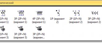
The next thing you should know is the symbol for power sockets and switches (including walk-through ones) on single-line diagrams of apartments and private houses:
Table 2 - Designation of switches, switches and sockets
| Name | Image | Name | Image | ||
| Switch. General image. | Plug socket. General image. | ||||
| Switch for surface installation with degree of protection from IP20 to IP23: | 1-pole | Surface-mounted socket with degree of protection from IP20 to IP23: | 2 pole | ||
| 1-pole double | 2 pole double | ||||
| 1-pole triple | 2-pole with protective contact | ||||
| 2-pole | 3-pole with protective contact | ||||
| 3-pole | |||||
| Switch for concealed installation with degree of protection from IP20 to IP23: | 1-pole | Recessed socket outlet with degree of protection from IP20 to IP23: | 2 pole | ||
| 1-pole double | 2 pole double | ||||
| 1-pole triple | 2-pole with protective contact | ||||
| 2-pole | 3-pole with protective contact | ||||
| Switch for surface installation with degree of protection from IP44 to IP55: | 1-pole | Plug socket with degree of protection from IP44 to IP55: | 2 pole | ||
| 2 pole | 2-pole with protective contact | ||||
| 3 pole | 3-pole with protective contact | ||||
| Two-way switch without zero position with degree of protection from IP20 to IP23: | 1-pole | Units with switches and two-pole sockets for surface installation with degree of protection IP20 to IP23: | One switch and plug socket | ||
| 2 pole | Two switches and a plug socket | ||||
| 3 pole | Three switches and a plug socket | ||||
| Two-way switch without zero position with degree of protection from IP44 to IP55: | 1-pole | Units with switches and two-pole socket socket for flush installation with degree of protection IP20 to IP23: | One switch and plug socket | ||
As for lighting elements, lamps and fixtures according to GOST are indicated as follows:
Table 3 - Images of lamps and spotlights with a combined image on the plan of equipment and electrical networks
| Name | Image | Name | Image |
| Lamp with incandescent lamp. General image | Chandelier | ||
| Lamp with incandescent lamp on a cable | Spotlight | ||
| A lamp with an incandescent lamp on the wall of a building, a structure for outdoor lighting. | A group of spotlights with the optical axis directed in one direction | ||
| Lamp with fluorescent lamps | A group of spotlights with the optical axis directed in all directions | ||
| Lamp with fluorescent lamps installed in a line | Signal traffic light (with three lamps) | ||
| Luminaire with fluorescent lamp on a bracket for outdoor lighting | Wall lamp socket | ||
| Luminaire with high pressure discharge lamp on bracket for outdoor lighting | Lamp holder: pendant | ||
| Luminaire with high pressure discharge lamp on pole for outdoor lighting | Lamp holder: ceiling |
In more complex circuits where electric motors are used, elements such as:
Table 4 – Conventional graphic designation of electrical machines
| Name | Image | Name | Image |
| Stator. Stator winding. General designation. | Rotor. General designation. | ||
| Rotor with winding, commutator and brushes. | The car is electric. General designation. | ||
| The machine is an asynchronous three-phase machine with six output phase ends of the stator winding and a squirrel-cage rotor. | Inside the circle, it is allowed to indicate the following data: a) type of machine (generator - G (G), engine - M (M), tachogenerator - TG (BR), etc.; b) type of current, number of phases or type of winding connection | ||
| The machine is an asynchronous three-phase machine with a wound rotor, the winding of which is connected in a star, the stator winding is connected in a triangle. | Three-phase non-salient-pole synchronous machine with excitation winding on the rotor; The stator winding is connected in a triangle. | ||
| DC machine with series excitation | DC machine with parallel excitation | ||
| Independently excited DC machine | DC machine with mixed excitation | ||
| DC machine with permanent magnet excitation | Single-phase commutator motor with sequential excitation. |
It is also useful to know how transformers and chokes are graphically indicated on circuit diagrams:
Table 5 - Conventionally graphic designation of transformers, autotransformers, chokes
| Name | Image | Name | Image |
| Winding of a transformer, autotransformer, choke and magnetic amplifier. | Single-phase transformer with magnetic core | ||
| Single-phase transformer with three-winding magnetic core | Single-phase autotransformer with magnetic core | ||
| Current transformer with one secondary winding | Choke with ferromagnetic magnetic core |
Electrical measuring instruments according to GOST have the following graphic designation on the drawings:
Table 6 - Conventionally graphic designation of some electrical measuring instruments
| Name | Image | Name | Image |
| Electricity meter | temperature sensor | ||
| Ammeter | Galvanometer | ||
| Voltmeter | Oscilloscope |
And here, by the way, is a useful table for novice mechanics and electricians, which shows what the ground loop looks like on the electrical wiring plan, as well as the power line itself:
Table 7 – Electrical communication lines, wires, cables and buses
| Name | Image | Name | Image |
| Electrical communication line, wire, bus, cable | Graphic intersection of two communication lines that are not electrically connected | ||
| Body of a machine, apparatus, device | Electrical communication lines with two branches | ||
| Grounding |
In addition, in the diagrams you can see a wavy or straight line, “+” and “-”, which indicate the type of current.
Table 8 – Type of current and voltage, types of winding connections, pulse shapes
| Name | Image | Name | Image |
| DC current | AC current, three-phase 50 Hz | ||
| AC current | Polarity negative | ||
| DC and AC current | Polarity positive |
In more complex automation schemes, you may encounter incomprehensible graphic symbols, such as contact connections. Remember how these devices are designated on electrical diagrams:
Table 9 - Switching devices and contact connections
| Name | Image | Name | Image |
| Switching device contact. General designation: | Limit switch contact: 1) normally open | ||
| A) closing B) opening B) switching | 2) opening | ||
| Manual switch | |||
| Contact closing with delay active: | contact contact | ||
| 1) when triggered 2) when returned | 1) detachable connection 2) prefabricated connection 3) permanent connection | ||
| 3) when triggered and returned | |||
| Delayed opening contact, active: 1) when triggered | Detachable contact connection | ||
| 2) upon return 3) upon activation and return | Single-pole multi-position switch | ||
| Thermal relay contact |
In addition, you should be aware of what radio elements look like on projects (diodes, resistors, transistors, etc.).
Table 10 – Conventional graphic designation (diodes, resistors, transistors)
| Diode |
| Zener diode |
| Thyristor |
| Photodiode |
| Light-emitting diode |
| Photoresistor |
| Solar photocell |
| Transistor |
| Capacitor |
| Throttle |
| Resistance |
Single-line electrical circuits also have their own letters, which make it clear what is included in the network. So, according to GOST 7624-55, the letter designation of elements on electrical circuits is as follows:
- Relays for current, voltage, power, resistance, time, intermediate, indicating, gas and time-delayed, respectively - RT, RN, RM, RS, RV, RP, RU, RG, RTV.
- KU – control button.
- KV – limit switch.
- CC – command controller.
- PV – travel switch.
- DG is the main engine.
- DO – cooling pump motor.
- DBH is a high-speed engine.
- DP – feed motor.
- DS – spindle motor.
In addition, in the marking of elements of radio engineering and electrical circuits, the following letter designations are distinguished:
Table 11 — Letter designations of elements of radio engineering and electrical circuits
| Name | Designation | Name | Designation |
| Resistor | R | Telephone | T |
| Capacitor | C | Microphone | Mk |
| Inductors | L | Speaker | Gr |
| Electronic device (lamp, tube) | L | Pickup (adapter) | Hell |
| Transformer (autotransformer) | Tr | Fuse | Etc |
| Throttle | dr | Galvanic element (battery) | B |
| Switch (switch) | IN | Circuit board | P |
| Button | Kn | Plug connector | Sh |
| Piezo element | Pe | Semiconductor device | PP |
| Diode | D | Nest | G |
| Relay, contactor, starter | R | Various elements, electromagnet | E |
How to insert a diagram into a term paper
Schemes can be inserted into coursework in two ways:
- in the form of ready-made drawings;
- using Word tools to help you create diagrams.
Inserting ready-made diagrams
The simplest option for placing a diagram in a coursework is to insert a ready-made diagram. It is done as follows:
- Place the cursor in the place where you want to place the diagram.
- Go to the “Insert” tab.
- Select the "Pictures" button.
- In the window that opens, find the required file.
- Select it and click “Insert”.
However, we remember that the diagrams that are placed in the coursework must be drawn up in the same style. And finding such examples on the Internet is almost impossible. A logical question arises: how to make an outline for a coursework yourself? Now we'll tell you.