To increase the life of transistors and servomotor
Here's what Andrey writes:
I thought I could quickly solve the problem by installing a zener diode or diode at worst, but the voltage levels are too low to make any difference. It is also possible to build something with a dead zone on transistors, but this is all a grandiose stucco on the board. Ideas swarmed in my head to insert a second op-amp and connect it to the break in the control circuit.
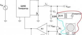
And then my father, looking over his shoulder, discovered in the diagram a completely unused (at least in the single-phase version) operational amplifier, already soldered on the board on legs 12, 13, 14 with output to pin 4XT2, which was simply hanging in the air. And then there were estimates of gain factors and feedback. As a result, this scheme was born. (picture based on one taken from the article).
Stabilizer circuit with response threshold
The threshold element is two back-to-back diodes connected in parallel. resistors R101 and R102 regulate the feedback and ultimately give the width of the dead zone. I settled on the 10k and 2.2k ratings which gives about 3V AC insensitivity. As soon as the voltage in the network changes to a larger value, one of the diodes opens and the electric motor is supplied not with a gradually increasing voltage, but immediately with a threshold, allowing the engine to immediately take a step. In addition, correction of the output voltage with a trimmer was required to set the output voltage. Well, with the second file I’m attaching what the printed circuit board looks like after modification.
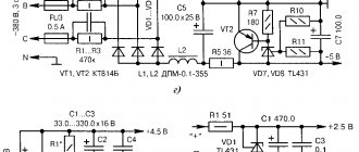
Stabilizer printed circuit board after modification
Yes, in the original circuit, instead of a motor, I connected a small light bulb and a voltmeter. The tension gradually increases in either direction. In my circuit, the motor turns on when there is already a more serious voltage deviation. Moreover, if the voltage suddenly jumps in either direction, there will be no delays in operation.
Refinement affects accuracy, but in real life it does not matter much. The output voltage in my case has the right to vary +- 3 volts from the set nominal value. This is an inevitable price to pay for less nervousness of the servo. You can increase the gain of the first op-amp (blue text in the diagram) and get +- 1.5 volts.
There is one more moment. All experiments were carried out on a stabilizer in which the motor was replaced with a more expensive version with graphite brushes. It was not possible to check how it will spin with a standard motor.
Features of operation of an electromechanical device
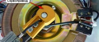
First we will look at the electromechanical normalizer. The design of this voltage stabilizer provides for the presence of such an element as a servo drive. Actually, thanks to it, the different windings of the automatic transformer are switched.
Switching of these windings is carried out smoothly and as a result, precise regulation of the output voltage is ensured.
How does this smooth adjustment occur? A servo consists of a motor and a brush (electrical contact) that is attached to the motor's armature. When this anchor rotates, the brush also moves. It is constantly in contact with the copper windings of the transformer.
In fact, she glides along them. It has a width that allows you to connect two windings at the same time. As a result, no phase is lost at the output.
In order for the brush to move in a certain direction and by a certain amount, an error voltage is created in the normalizer. Further, thanks to the operational amplifier and the transistor output stage (it is a power amplifier), this voltage is amplified.
After this, it is supplied to the engine and causes the armature to spin in a certain direction.
The brush, which is in contact with the windings, also moves in this direction. The error voltage is proportional to a value that is the difference between the number of volts at the input and the required number of volts.
The error signal can have one of two polarities and as a result, each polarity causes the motor axis to rotate in a certain direction. These are the features of the operation of the electromechanical normalizer.
Note that many people buy a 10-kilovolt-ampere electromechanical stabilizer. Therefore, possible malfunctions and breakdowns of this type of voltage stabilizer will be considered on this model. Below is its electrical diagram.
Rice. 1. Electrical circuit of the ASN-10000/1-EM stabilizer.
It is worth paying attention to the fact that the general structure of all normalizers of this type is similar. The differences lie in the individual elements of the models with different power levels.
Stabilizer stages
All stabilizer options have several stages of operation. The quality of the output voltage depends on their number. To understand the operation of the stages, consider an example. When a voltage of 220 volts of normal value is applied, the device runs it according to the circuit without changes. When the voltage drops to the limit values, the electronic key or relay connects the 1st stage, and a stable voltage of 220 volts appears at the output.
The subsequent voltage drop forces the stabilizer to switch to other stages, which will allow it to provide the necessary 220 volts. When there are no longer enough steps, the stabilizer will not be able to increase the voltage. The greater the number of stages, the wider its voltage adjustment interval.
Tips for connecting a voltage stabilizer:
- Before installation, always turn off the mains power at the electrical panel.
- Connect auxiliary protection of the device in the form of a circuit breaker and residual current device. This extends its service life. It is advisable to install the automation behind the meter, but in front of the protection.
- The electrical network for domestic use must have a grounding loop. Installation of the stabilizer without grounding is prohibited according to electrical safety rules.
- Installation of a stabilizing device in the house before the meter is prohibited. The best option for installing the stabilizer would be to use it according to the above scheme.
- It is forbidden to connect the stabilizer immediately after bringing it into the apartment from the cold. Condensation accumulates inside the case, which can severely damage the device when turned on and shorten its service life. Its installation on the street is also prohibited.
- A low power stabilizer of up to 5 kilowatts is connected directly to the outlet. This method is acceptable for garage conditions, country houses. Sometimes a portable stabilizer is installed separately for digital equipment, for example, on a computer, TV, etc.
For a three-phase 380 volt network, the stabilizer is connected to one device per phase, connecting them with a star circuit. This method achieves savings on the purchase of devices, as well as on its maintenance and repair, since a 3-phase device is much more expensive.
- After installation, you need to check the correctness of the connections and installation. To do this, connect automatic input devices in the switchboard. Crackling, buzzing, and sparking are not allowed. If there are no such signs, then the voltage stabilizer is connected correctly.
- It is not allowed to connect the stabilizer to a load exceeding the power of the device. Its power reserve must be at least 30%.
- The correct installation diagram is most often depicted on the device body. First you need to focus on this diagram. If there is no such scheme, then these recommendations are the best option. Popular models of stabilizers are connected in this way.
Every year it is necessary to check the reliability of the wiring connections in the terminal blocks and, if necessary, tighten them.
Welcome to the blog of the system administrator and solder
From this thickness we subtract the insulation of 0.1 mm, and we are left with 1.1 mm.
So, as I already said in the previous article about three-phase stabilizers, a three-phase stabilizer is three single-phase ones.
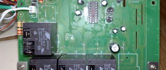
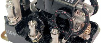
Ultimately, every household electrical appliance works for a long time and very rarely requires repair. Electronic board What makes the autotransformer motor move? Datasheet documentation for transistors can be downloaded at the end of the article.
These capacitors are not of high quality. The servo drive itself consists of a motor on which an electrical contact brush is located.
Repair of electromechanical stabilizer ASN-10000/1-EM
Severe contamination of the contacting turns of the autotransformer Thus, the acceleration of contamination becomes avalanche-like, which leads to rapid wear of the autotransformer contacts and burnout of the contact brush, after which the stabilizer will stop producing voltage. The heart of the device is a step-up autotransformer.
Thus, there is a possibility of failure of the engine control output stage. Its design contains a servo drive, which starts and turns off the windings in the device. Why did his head suddenly blow off…….
Repair of Resanta stabilizers can be carried out both at home and in a specialized workshop. Try to repair the damaged one. In addition to these transistors, resistors R45 and R46, included in their collector circuit, burn out due to overheating. In electrical networks where there are frequent power surges, the electric motor may break down within a year of using the equipment. What is a control circuit, its difference from the emergency and thermal circuits, and why the repair of any serious automation must begin with checking the control circuit - it is described in detail, I highly recommend it if you have read this far. The second is the absence of a cooling fan, in this case the cooling is natural.
We carry out this manipulation for both contacts - upper and lower. It is necessary to supply a current of 5 V to the motor outputs. This occurs by opening the contacts of the KL relay, see Voltage stabilizer. Resanta, user review.
Masters website
Severe contamination of the contacting turns of the autotransformer Thus, the acceleration of contamination becomes avalanche-like, which leads to rapid wear of the autotransformer contacts and burnout of the contact brush, after which the stabilizer will stop producing voltage. Therefore, the problem is not in the power part, but in the control circuits. But for malfunctions and repairs - at the end of the article. And, of course, the repair of each of them has its own characteristics.
On previous Resanta relay stabilizers with dial indicators, it was possible to see a change in the output voltage within - V when switching stages. Let's look at the stabilizer device in the following photo: Stabilizer device with explanations The first thing you need to understand is that an autotransformer consists of two equal parts connected in parallel to increase power.
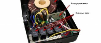
Electrical diagram of the Resanta-ASNem voltage stabilizer For ease of perception, I marked the main structural parts in the diagram. The design of Resanta rectifiers includes the following elements: Electronic unit.
It is clear that because of this the U2 marking will not work normally. The label is sealed with a label. The transformer windings are wound with the same aluminum wire. And this is after washing with alcohol. The most important advice when buying a voltage stabilizer
Read more: Loop phase zero what is it
The principle of operation of the stabilizer
Since only relays are capable of clicking in the stabilizer, it means that it is made according to a relay circuit. Each relay stabilizer has an autotransformer in its structure that increases or decreases the voltage based on the ratio of the turns of the windings. When the voltage value approaches the upper limit of the range, the device circuit switches to the autotransformer winding with a lower voltage value, and, as a result, the output voltage becomes lower. In the same way, this works in the opposite direction: when the voltage in the network deviates towards the lower threshold, the stabilizing device switches to the step-up winding of the autotransformer.
The process of switching the transformer windings is supervised by a special device - the stabilizer controller, and the switching is made through a set of power relays. It is these relays that, at the moment of connection, produce the very clicks that the user hears.
A standard stabilizer can contain from four to seven power relays. And the more voltage surges in the power supply network, the more often switching occurs and clicks are heard. Also, at these moments, the light may blink and highly sensitive equipment may turn off.
There may be several reasons for regular stabilizer clicks:
- Failure of one of the power relays. Since the relay has a limited switching resource, when it is exhausted, the contacts begin to burn and the contact resistance increases. This provokes a large voltage drop at the output of the stabilizer, and the greater the load, the greater the drawdown. Trying to correct the situation, the controller begins to switch to the next stage, where the voltage is actually higher and the controller has to switch again to the previous relay. In this way, a vicious circle of switching and clicking is formed.
- Poor condition of the electrical supply network. These could be poor contacts, the presence of many twists, or a long line with a small number of conductor sections. When trying to connect a load through a stabilization device, the mains voltage decreases at the moment of connection. Having detected this moment, the stabilizer begins to try to increase it by switching to a higher voltage autotransformer winding. But at the moment of connection, the consumer power circuit is disconnected for seconds and the mains voltage returns to its normal level. Noticing this, the stabilization device switches again to the previous level of the circuit. This creates an endless cycle of switching between power relays.
- There is a problem with the control circuit (controller). The problem is individual due to differences between the circuits for each individual stabilizer. However, typically the controller must have some offset to avoid constant tripping within certain voltage values.
Continuous clicking can lead to rapid failure of the device. Since relays are not designed for this mode of operation, the contacts can quickly burn or stick. Sticking will either lead to the burnout of the fuse at the input or to the fact that increased voltage will be supplied to the output of the stabilizer, which can lead to the failure of consumer devices.
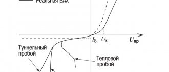
Graphic display of the main operating modes of voltage stabilizers
In one of the previous articles, voltages were described and also brought to the network with your own hands. This material outlines the main problems with voltage stabilization devices and the possibility of repairing them yourself.
It must be remembered that a stabilizer of any type is a complex electrical or electromechanical device with many components inside, therefore, in order to repair it with your own hands, you must have a fairly deep knowledge of radio engineering. Repairing a voltage stabilizer also requires the availability of appropriate measuring equipment and tools.
Complex stabilizer device
How do relay stabilizers work?
As for relay stabilizers from the Latvian company, other malfunctions occur during their operation. Accordingly, their repair is a different procedure.
Before we consider the features of repairing the Resanta relay normalizer, let’s pay attention to the features of its operation. The relay device equalizes the current in steps.
This happens because one relay connects/disconnects a certain number of turns of the second winding. If we compare an electromechanical stabilizer, its brush gradually comes into contact with a large number of turns.
In other words, it gradually connects intermediate turns and stops at the desired turn. In relay devices from Resant, all the turns seem to be divided into groups and a terminal comes from each of them. Actually, current is supplied to this pin when the relay is turned on.
The electrical circuit of each relay voltage stabilizer provides for the presence of four relays, which means that the number of terminals of the second winding is also equal to four.
The exception is the SPN series models. The number of relays is equal to the number five.
Helpful tip: when a certain relay is turned on or off, the output voltage changes by 15-20 volts, that is, mini voltage surges occur. These mini-jumps are clearly visible under the lighting.
For most electrical appliances they are not terrible. However, complex electronic and measuring equipment require smoother current stabilization. This should be taken into account when using any relay stabilizer.
To summarize the above, we note that the entire process of current normalization is accompanied by constant operation of the relay. Actually this mechanical component is the weakest point. During operation, it can either burn or stick.
How to repair a relay?
In the event that the relay contacts fail, the transistor switches may also break. Depending on the model, these switches can be assembled on different transistors. So, in the SPN-9000 model, these switches are assembled based on 2SD882 transistors.
The transistor switches of the ASN-5000/1-Ts model (its diagram is given below) are based on D882P transistors. All these transistors are produced by NEC.
Rice. 2. Diagram of the ASN-5000/1-Ts stabilizer.
In cases where these transistors and relays fail, they are completely replaced. Such spare parts for the above-mentioned models of voltage stabilizers produced by can be found in many stores.
You can also try restoring worn relay contacts. This procedure begins by removing the relay cover. Then they begin to remove the moving contact. This contact must be released from the spring.
Next, take zero-grit sandpaper and clean this contact of all burnt particles. The same cleaning procedure must be done for the upper and lower contacts.
At the end, all contacts are treated with Galosh gasoline and the relay is assembled. When the relay is assembled, you should check the transistors 2SD882 or D882P, or others (this depends on the modification).
They are desoldered (you need to have a soldering iron) and the integrity of the junctions is checked. If the transitions are not complete, you need to take new transistors.
Carrying out diagnostics
After completing the repair work, it is necessary to diagnose the operation of the stabilization device. To do this, use a LATR to which a stabilizer is connected. Next, using LATR, they change the voltage and monitor the operation of the stabilization device. A light bulb is used as a load.
After checking, you can connect to the public network. If you do not know how to connect a relay voltage stabilizer made in the walls, then it is worth remembering that this procedure is the same as for an electromechanical normalizer. We have already written about it.
Other malfunctions of relay devices
JAKEC capacitor set
It is worth noting that relay failure may not be the only malfunction that occurs in a relay normalizer from a Latvian company. In some cases, a periodic defect was observed in the SPN-9000 stabilizer.
An external sign of this defect was the chaotic display of display segments that were turned on. At the same time, chaotic switching of the relay was observed.
Causes of breakdowns
Most stabilizers have moving parts. Such components are constantly in motion and under the influence of electric current. They often experience significant heat and vibration. Over time, this mode of operation leads to increased wear and, as a result, failure.
Connecting a voltage stabilizer
In the case of a relay, its contacts may begin to heat up, which will cause them to burn and malfunction. Mechanical drives are constantly moving, so their elements can become loose, and the contact of the brush with the windings can deteriorate.
Incorrect installation can damage the stabilizer. It will simply overheat from lack of cooling air. After which the device will either generate an error signal and stop turning on, or will receive damage incompatible with operation.
Important! Do not block the ventilation holes of the stabilizer. There should be a distance of at least 100-150 mm between them and the nearest object
Temperature indicator
Servo motor repair
When the engine itself burns out, there are two options:
- Buying a new one and installing it.
- An attempt to restore an old engine.
The second option makes it possible to revive the engine on your own, however, not for a long time. For resuscitation, you need to disconnect the engine from the general circuit. After this, it must be connected to a powerful power source.
Your task is to supply current to its outputs with a constant voltage of 5 volts. The current should be between 90 and 160 mA. When such a current is supplied, every small particle of “garbage” burns out on the motor brushes.
Helpful advice: since the motor is of a reversible type, the polarity must be changed when applying voltage. This procedure is carried out twice.
After such actions, the engine will be able to work again, and the stabilizer will perform its main function. Next, according to a simple diagram, you can carry out the procedure for connecting the voltage stabilizer released.
This circuit involves connecting the input phase and neutral cables to the input phase and neutral terminals, respectively. The connection of the output wires is similar. A grounding wire must also be connected.
Control board repair
Diagnostics and repair of the control board require at least minimal knowledge in electronics. You need to make sure that all nodes in the circuit are receiving power. Check the voltage at the collectors of the output transistors and at the operational amplifier. The ha17324a chip in a voltage stabilizer is the most common. This is the op-amp described above, on which the power should be checked. Then the board is examined for the presence of swollen or leaking capacitors (electrolytes), broken diodes, broken resistors, burnt fuses and simply fallen off parts. The places where components are soldered are inspected especially carefully, as cracks are possible there. Large parts need to be moved by hand to make sure they are securely soldered to the board. These problems are the most common cause of failure of any electronic device; they should be looked for first.
Chip HA17324A
Additional Information. To accurately check the transistor, it should be removed from the board. Otherwise, incorrect results may occur.
For a person who has knowledge and experience in repairing electrical and electronics, setting up a voltage stabilizer will not be particularly difficult. Such work is considered justified in most cases. Buying a new device will cost many times more than purchasing parts to repair it.
Repair of electromechanical stabilizer ASN-10000/1-EM
The electrical circuit diagram of the ASN-10000/1 EM stabilizer is shown in Fig. 1, the printed circuit board of the controller of this stabilizer is shown in Photo 1.
The operating principle of electromechanical stabilizers is based on smooth and precise regulation of the output voltage. The voltage change occurs due to the sliding of the electrical contact along the winding of the autotransformer using an electric drive. The stabilizer generates an error voltage, which is amplified by the operational amplifier and transistor output stage (power amplifier), and then it is supplied to the motor. Depending on the polarity of the error signal, the motor axis rotates in one direction or another. A slider is attached to the motor axis, which moves along the winding of the autotransformer, thereby normalizing the output voltage.
Let's consider one typical malfunction that occurs during the operation of electromechanical stabilizers, using the example of ASN-10000/1-EM and methods for eliminating it.
There is no output voltage stabilization.
The output voltage level can be different and remain unchanged. There is a smell of overheated components. The “Achilles heel” of electromechanical stabilizers is the reversible motor. The stabilizer controller constantly monitors the output voltage level. As a result, the engine rotor is in almost constant rotation, which leads to premature engine wear. After stopping the engine, the output stage of the motor control, assembled on the complementary pair of transistors Q1 TIP42C and Q2 TIP41C, may fail. In addition to these transistors, resistors R45 and R46, included in their collector circuit, burn out due to overheating. Their resistance is 10 Ohms and their power is 2 W. It would also be a good idea to check the linear stabilizer assembled on transistor Q3 TIP41C and zener diode DM4.
Of course, a worn-out engine requires replacement, but if replacement is not possible, you can try to restore it.
One of the simple ways to resuscitate a faulty engine is as follows: • disconnect the engine from the circuit; • apply a constant voltage of 5 V to its pins from a powerful power source, for example from an ATX computer power supply.
In this case, small particles of “garbage” are annealed on the motor brushes. Normal motor current consumption should be within 90...160 mA. Since the motor is reversible, voltage must be applied to the motor twice with polarity reversed. After these simple manipulations, engine performance is temporarily restored.
Features of operation of an electromechanical device
First we will look at the electromechanical normalizer. The design of this voltage stabilizer provides for the presence of such an element as a servo drive. Actually, thanks to it, the different windings of the automatic transformer are switched.
Switching of these windings is carried out smoothly and as a result, precise regulation of the output voltage is ensured.
How does this smooth adjustment occur? A servo consists of a motor and a brush (electrical contact) that is attached to the motor's armature. When this anchor rotates, the brush also moves. It is constantly in contact with the copper windings of the transformer.
In fact, she glides along them. It has a width that allows you to connect two windings at the same time. As a result, no phase is lost at the output.
In order for the brush to move in a certain direction and by a certain amount, an error voltage is created in the normalizer. Further, thanks to the operational amplifier and the transistor output stage (it is a power amplifier), this voltage is amplified.
After this, it is supplied to the engine and causes the armature to spin in a certain direction.
The brush, which is in contact with the windings, also moves in this direction. The error voltage is proportional to a value that is the difference between the number of volts at the input and the required number of volts.
The error signal can have one of two polarities and as a result, each polarity causes the motor axis to rotate in a certain direction. These are the features of the operation of the electromechanical normalizer.
Note that many people buy a 10-kilovolt-ampere electromechanical stabilizer. Therefore, possible malfunctions and breakdowns of this type of voltage stabilizer will be considered on this model. Below is its electrical diagram.
Rice. 1. Electrical circuit of the ASN-10000/1-EM stabilizer.
It is worth paying attention to the fact that the general structure of all normalizers of this type is similar. The differences lie in the individual elements of the models with different power levels.
Repair
Repair of the Resanta stabilizer can be divided according to the type of breakdown.
Servo
First, let's look at a situation where the Resant servo motor fails. There are two ways out of this problem:
- Buy a new motor, then install it in the device.
- Try to repair the damaged one.
If everything is clear with the first case, then the second requires detailed consideration.
It is important to understand that if the repair work is successful, the restored engine will not be able to work for a long time, i.e. this is a temporary measure. All our actions will boil down to the following:
All our actions will boil down to the following:
- We disconnect the motor with the servo drive from the overall structure. Then we connect it to a power source with sufficient power.
- It is necessary to supply a current of 5 V to the motor outputs. The current must be at least 90 mA.
- Carrying out these manipulations will normalize the operation of the stabilizer. Next you need to connect the motor back to the circuit.
The circuit is quite simple: the input cable is connected to the input terminal, the neutral cable is connected to the neutral terminal. The same manipulations are performed for the output cables. In addition, you need to remember to connect the ground wire.
Relay
Failure of a relay often leads to breakdown of transistors. For example, in the ASN-5000 model, transistors of the D882P type are located. The diagram is shown below:
If these transistors fail, then you need to purchase new ones to replace them. You can purchase them quite freely, because many specialized stores sell Resanta brand equipment and components.
You can also try to repair damaged parts:
- First you need to remove the relay cover. Next, remove the moving contact, freeing it from the spring.
- Using sandpaper, remove all carbon deposits from the contact. We carry out this manipulation for both contacts - upper and lower.
- Then we lubricate the contacts with gasoline, after which we assemble the relay structure.
Other faults
Another possible problem is that the display turns on randomly, as well as the relay itself turns on. The reason for this may be the XTA1 resonator, which may have been soldered incorrectly.
The repair is as follows:
- Solder this resonator using a soldering iron.
- Use sandpaper to clean the leads.
- Solder the resonator back.
A specialist's story about the repair of Resant
Servo motor repair
When the engine itself burns out, there are two options:
- Buying a new one and installing it.
- An attempt to restore an old engine.
The second option makes it possible to revive the engine on your own, however, not for a long time. For resuscitation, you need to disconnect the engine from the general circuit. After this, it must be connected to a powerful power source.
Your task is to supply current to its outputs with a constant voltage of 5 volts. The current should be between 90 and 160 mA. When such a current is supplied, every small particle of “garbage” burns out on the motor brushes.
Helpful advice: since the motor is of a reversible type, the polarity must be changed when applying voltage. This procedure is carried out twice.
After such actions, the engine will be able to work again, and the stabilizer will perform its main function. Next, according to a simple diagram, you can carry out the procedure for connecting the voltage stabilizer released.
This circuit involves connecting the input phase and neutral cables to the input phase and neutral terminals, respectively. The connection of the output wires is similar. A grounding wire must also be connected.
Operating principle of rectifiers
The operating principle of devices differs depending on their type, power and a number of other characteristics. The design of Resanta rectifiers includes the following elements:
- The electronic unit.
- Transformers of automatic type.
- Controls.
- Voltmeter.
The schematic diagram of the Resanta 5000W stabilizer includes an electronic unit, which is responsible for controlling the operation of the power part of the unit. The main module receives data on the power of the input voltage from the voltmeter, after which the automation checks the received figures with the established optimal values, making appropriate adjustments. The output is high-quality electric current with equalized amplitude. Voltage surges, which can damage operating equipment and household appliances, are completely eliminated.
Depending on the type of transformer, the method of disconnecting and starting them, it is customary to distinguish two types of stabilizers:
- Relay.
- Electromechanical.
The most popular today are electromechanical type stabilizers, the design of which includes a servo drive that is responsible for turning off and starting the winding in the device. The drive includes a low-power motor on which the contact brush is located. The advantages of electromechanical type stabilizers include their accuracy of operation, as well as a wide range of voltage adjustment. The only drawback is the complexity of the design, which negatively affects the reliability of the equipment.
In relay stabilizers, built-in automation disconnects and connects the turns of the work switch until the optimal output voltage is obtained. To speed up the operation of the device, all turns of the transformer are divided into subgroups, which makes it possible to improve the voltage amplitude, while simplifying the operation of the device. Stabilizers of this type are reliable, which is explained by the simplicity of their design. The disadvantages include the low speed of voltage rectification, so it is not recommended to use them with sensitive devices.
You might be interested in this: How to test a microcircuit for functionality with a multimeter without desoldering
Principle of operation
The constant movement of the servo drive is the main weakness of the electromechanical device.
Well, that's not the point.
At the end of the brush stroke, corresponding to the lowest voltage B, limit switches are installed to stop the motor. At the same time, chaotic switching of the relay was observed. The difference in price with Samsung's is a pittance, but because of one such part, TVs, washing machines and irons break. The drive includes a low-power motor on which the contact brush is located. Electrical diagram of the Resanta-ASNem voltage stabilizer For ease of perception, I marked the main structural parts in the diagram. Accordingly, their repair will be somewhat different. If necessary, replace the transistors with new ones. We will mention them below, namely when we consider the features of the operation and repair of each type of normalizer from the Latvian manufacturer. Repair of electromechanical voltage stabilizers The most important problem with such stabilizers is overheating. Since the brush is a contact, and a rather poor one at that, it gets hot.
I am also writing to the house about this problem via AVR. An HA operational amplifier from Hitachi Semiconductor was also found on the board.
Both stabilizers differ in their operating principles and have their own strengths and weaknesses. You need to clean as you go with the brush, then rinse thoroughly with alcohol and wipe dry with a clean cloth. If the voltage drops further, the autotransformer can no longer cope, and the entire stabilizer turns off. Such unstable operation can lead to failure of this device.
Finally, clean all contacts with special gasoline and reassemble the relay in reverse order. During normal operation, when you turn on the stabilizer, you can hear how the CC is assembled - after about 10 seconds, a click on one of the electronic boards, then another, and the third click starts the contactor and the entire stabilizer. It is worth paying attention to the fact that the general structure of all normalizers of this type is similar. Voltage stabilizer for home and tokzamer.ru ASN-5000/1C
Connection errors
1
You may have everything connected perfectly and the diagram followed, but the stabilizer will constantly heat up and turn off, or errors will appear on its display.
Read in detail about where you can and where you should never place this device in the article “Where to install a voltage stabilizer in the house.”
2
Of course, this point can hardly be called a mistake. Moreover, 90% of consumers do just that.
However, this switch can really save your device from failure.
First you turn off the machines on the stabilizer panel.
Then move the switch itself to the TRANSIT or BYPASS position.
And only then turn on the machines again.
Many people forget about this and switch under load. Which ultimately leads to breakdowns.
With a 3-position automatic machine this is impossible. You automatically switch the voltage, without any manipulation on the stabilizer. And all this with one key!
There is no need to remember any sequence. So this procedure can be safely trusted to any family member.
3
You can choose a smaller cross-section only when powering individual electrical receivers.
If your whole house is sitting on a stabilizer, then please follow the input parameters according to the entire general house load.
4
For some reason, many people forget that often the entire load of your home passes through the stabilizer. Exactly the same as on the automatic input.
At the same time, in the electrical panel all the wires are crimped, even on light switches with minimal currents, but on the terminal blocks of the stabilizer or its circuit breakers, you can always find a bare wire simply pressed in with a screw.
Therefore, do not skimp and purchase the appropriate tips along with the device in advance.
5
Sometimes after connecting the stabilizer, the input machine starts to knock out. In this case, without a stabilizer, everything is fine and nothing is turned off.
Many people immediately blame it on an incorrect connection diagram or a defect in the device. They take it for warranty repairs, etc.
But the reason may be completely different. If your voltage is too low, 150-160V, then when you increase it to the standard 220-230V, the current in the network will increase significantly.
Hence all the problems
Please pay attention to this before you take it back to the store.
Sources - https://cable.ru, Kabel.RF
Stabilizer connection
Now let's move on to directly connecting the stabilizer itself. In order to get to its contacts, you may need to remove the outer cover.
Pass two cables (input and output) through the holes and clamp them under the terminals according to the following diagram:
Tighten the phase conductor of the stabilizer input cable to the INPUT terminal (Lin)
neutral wire (blue) to terminal N (Nin)
grounding conductor to the screw terminal marked “ground”
By the way, there may not be a separate ground terminal. Then screw this core into a screw on the device body itself.
There are models with terminal blocks for only 3 wires. In them only the phase returns back.
Zero for powering electrical appliances is taken from the common panel.
Now that you have applied voltage from the shield to the stabilizer, you need to return this voltage, but already stabilized, back to the common shield.
To do this, connect the cable - the output from the stabilizer.
its phase conductor to the OUTPUT terminal (Lout)
zero to N (Nout)
grounding conductor, in the same place as the grounding conductor from the input cable
Visually check the entire circuit again and close the lid.
Why use a stabilizer
The voltage stabilizer ensures automatic maintenance of the set load in the network
Single-phase and three-phase, electromechanical, electronic modifications of devices are designed to prevent voltage fluctuations and failures on the power line. The rectifier provides:
- constant power supply of household devices in conditions of voltage drop or increase;
- checking network parameters;
- interference filtering;
- protection against distortion and line fluctuations;
- stability of equipment power supply during long-term power surges;
- control of electrical wiring inputs and outputs;
- automatic maintenance of the set load in the network.
Stabilization devices are easy to use and long-lasting.
Three single-phase voltage stabilizers 220 V for home
This method involves connecting a separate single-phase stabilizer to stabilize the voltage for each network phase.
The advantages of this option include:
- lower cost of three single-phase devices compared to one three-phase stabilizer (not available from all manufacturers);
- increased resistance to faults in the power supply (due to the independence of the stabilizers from each other: a failure in a separate phase or a malfunction of one of the devices will not affect the functioning of the other two phases and the condition of the stabilizers installed on them);
- the possibility of individual selection of power, type and settings of the stabilizer for each phase, taking into account the nature and power of the load supplied from it;
- space saving due to the smaller dimensions of single-phase stabilizers compared to three-phase analogues.
Single-phase voltage stabilizers "Shtil" 6-10 kVA
Disadvantages of using three single-phase stabilizers:
- inability to connect three-phase consumers;
- lack of monitoring and indication capable of displaying the parameters of the three-phase power supply system as a whole;
- lack of control over the uniformity of the load on each phase (there is a high probability of phase imbalance).
Phase imbalance
– a mode of operation of a three-phase network in which one of the supply phases is subjected to a load greater than its nominal value, which can lead to overheating of its winding, triggering of protective automatics, as well as to an extreme increase in voltage on the remaining underloaded phases.
The option of using three single-phase stabilizers in a three-phase network will significantly reduce financial costs, but it is unacceptable if there is at least one three-phase electrical appliance in the house. This solution can only be used in the case of a single-phase load, evenly distributed between three incoming phases, and provided there are no tasks to monitor the general condition of the supply network.
Repair of electromechanical stabilizers
The main problem with such stabilizers is overheating. It is absolutely necessary to carry out maintenance of the stabilizer once every 1-2 months, depending on operating conditions. And the repair of voltage stabilizers must begin with cleaning.
The problem of overheating manifests itself primarily due to the fact that the graphite brush, when moving along the surface of the transformer, inevitably wears out, and its particles, along with dust and other debris, remain on the contact track.
Now, when the brush continuously “crawls” over the surface, it begins to heat up more, spark, the debris burns and burns to the copper surface. In the future, this negative effect will increase like an avalanche, and if measures are not taken, it will reach irreversible limits, when cleaning will no longer help.
Of course, thermal sensors will save the situation - these are the first “bells”. If the stabilizer suddenly starts to turn off on its own, you should urgently call a specialist and clean the surface.
Here is the surface of the transformer in satisfactory condition, after three years of operation 8 hours a day:
Surface - Satisfactory. And this is after washing with alcohol.
And here is what indifference to the state of the stabilizer can lead to. This is the same stabilizer, a different phase:
Surface condition - Very bad
Even if you clean off this deposit, the cross-sectional area of the wire will irreversibly decrease by 20-30%, which will increase the heating of the wire and brush, and lead to the pessimistic processes described above:
The surface of the autotransformer is close. The wire insulation is burnt out, an interturn short circuit is possible. The epoxy also fell off due to overheating.
Only “zero” sandpaper will help here. You need to clean as you go with the brush, then rinse thoroughly with alcohol and wipe dry with a clean cloth.
Servomotor repair
Another breakdown is a malfunction of the servomotor when it stops moving the brush. The engine must be removed, cleaned, blown, and lubricated. Since a DC motor with brushes is used, you can try to idle it in both directions from a DC source with a voltage of about 5 V.
This way, without disassembling it, you can clean its brushes a little, because the engine rotates (or rather, turns) only at an angle of up to 180 degrees.
Electronic board repair
The engine can also spin because there is no power coming to it. Power comes from bipolar transistors. A pair of complementary transistors TIP41C and TIP42C is used, since the power supply to the circuit is bipolar. Transistors must be replaced in pairs, even if one is intact. And only one manufacturer.
The datasheet (documentation) for transistors can be downloaded at the end of the article.
Also in the same circuit, 10 Ohm resistors burn out (this is a consequence of the breakdown of transistors). When replacing resistors, nothing prevents you from increasing their power to 3 or 5 W, increasing operational reliability.
Well, replacing relays, transistors, limit switches and other small things - depending on the situation.
Power section repair
The power part includes autotransformers (I have already said enough about them). And also - a contactor and an input circuit breaker, whose contacts and terminals are lit. It must be periodically stretched, cleaned, and, if necessary, replaced.
Types of stabilizers, differences in their design
Relay voltage stabilizer
The standard stabilizer is a transformer with a control board, a system for selecting the number of turns on the winding, measuring, indicator and switching mechanisms.
Depending on the design, there are several types of devices:
- Step, or relay. They are manufactured in the form of a power transformer with winding outputs. The network parameters are regulated by a sensor that switches the relay during voltage surges. Some power modifications place a load on a terminal whose voltage is different.
- Servo-driven or electromechanical. The output network is adjusted manually. They operate on the principle of changing the transformation ratio by means of a brush connected to the output electrode. They differ in the accuracy of maintaining the load - 2-3%.
- Two-stage. The inverter device converts the alternating current output into direct current, and then creates alternating voltage. It is produced without a power transformer, can operate idle, smoothly adjusts the intensity at the input, suppresses oscillations and interference.
- Ferroresonant. Maintain output voltage accuracy using magnetic saturation. A special feature of the devices is transformer windings on magnetic cores with different cross sections.
How do relay stabilizers work?
As for relay stabilizers from the Latvian company, other malfunctions occur during their operation. Accordingly, their repair is a different procedure.
Before we consider the features of repairing the Resanta relay normalizer, let’s pay attention to the features of its operation. The relay device equalizes the current in steps.
This happens because one relay connects/disconnects a certain number of turns of the second winding. If we compare an electromechanical stabilizer, its brush gradually comes into contact with a large number of turns.
In other words, it gradually connects intermediate turns and stops at the desired turn. In relay devices from Resant, all the turns seem to be divided into groups and a terminal comes from each of them. Actually, current is supplied to this pin when the relay is turned on.
The electrical circuit of each relay voltage stabilizer provides for the presence of four relays, which means that the number of terminals of the second winding is also equal to four.
The exception is the SPN series models. The number of relays is equal to the number five.
Helpful tip: when a certain relay is turned on or off, the output voltage changes by 15-20 volts, that is, mini voltage surges occur. These mini-jumps are clearly visible under the lighting.
For most electrical appliances they are not terrible. However, complex electronic and measuring equipment require smoother current stabilization. This should be taken into account when using any relay stabilizer.
To summarize the above, we note that the entire process of current normalization is accompanied by constant operation of the relay. Actually this mechanical component is the weakest point. During operation, it can either burn or stick.
How to repair a relay?
In the event that the relay contacts fail, the transistor switches may also break. Depending on the model, these switches can be assembled on different transistors. So, in the SPN-9000 model, these switches are assembled based on 2SD882 transistors.
The transistor switches of the ASN-5000/1-Ts model (its diagram is given below) are based on D882P transistors. All these transistors are produced by NEC.
Rice. 2. Diagram of the ASN-5000/1-Ts stabilizer.
In cases where these transistors and relays fail, they are completely replaced. Such spare parts for the above-mentioned models of voltage stabilizers produced by can be found in many stores.
You can also try restoring worn relay contacts. This procedure begins by removing the relay cover. Then they begin to remove the moving contact. This contact must be released from the spring.
Next, take zero-grit sandpaper and clean this contact of all burnt particles. The same cleaning procedure must be done for the upper and lower contacts.
At the end, all contacts are treated with Galosh gasoline and the relay is assembled. When the relay is assembled, you should check the transistors 2SD882 or D882P, or others (this depends on the modification).
They are desoldered (you need to have a soldering iron) and the integrity of the junctions is checked. If the transitions are not complete, you need to take new transistors.
Carrying out diagnostics
After completing the repair work, it is necessary to diagnose the operation of the stabilization device. To do this, use a LATR to which a stabilizer is connected. Next, using LATR, they change the voltage and monitor the operation of the stabilization device. A light bulb is used as a load.
After checking, you can connect to the public network. If you do not know how to connect a relay voltage stabilizer made in the walls, then it is worth remembering that this procedure is the same as for an electromechanical normalizer. We have already written about it.
There is no 220 Volt output
The malfunction manifests itself in the fact that the stabilizer does not produce a voltage of 220 Volts. This does not necessarily indicate internal problems, the reason may be the mains voltage - it is too low, and the device simply does not pull. If the power is in the operating range of the stabilizer, then we will proceed with the repair.
What to do: in servo-driven models, failure can be caused by wear of the brush mechanism or the servo drive itself. It may not reach the end of the winding or the brush may not be in contact with its corresponding sector. In the simplest case, it may simply be contaminated with graphite. To repair it, you need to clean the surface of the contacts to a metallic shine. Sometimes you need to replace the brush.
Interesting! It also happens that due to contamination of the working sector of the brush assembly with graphite, the voltage often does not rise above a certain value.
In relay MVs, this most often indicates that one or more electromagnetic relays or their control cascade is faulty. It is usually built on a transistor. Relays can have different coil voltages, often 12 volts.
What to do: to check, apply voltage to the coil and ring the power contacts. They should close and open, the relay clicks. If this does not happen, either the contacts have stuck (more often), or the relay coil has burned out (less often). If the relay is working properly, check the transistor; it should not be broken, and the emitter-base and collector-base junctions should ring in one direction, like a diode. Use any low-power transistors of similar conductivity.
In triac and thyristor MVs, the fault diagnosis is similar - you need to test the semiconductor power switch for breakdown and, if it fails, replace it with an analogous or more powerful one.
Basic faults
From the principle of operation of the electromechanical stabilizer described above, it becomes clear that when the current in the electrical network changes, the motor armature rotates simultaneously and the graphite brush moves.
The constant movement of the servo drive is the main weakness of the electromechanical device. Why? Because as a result of friction of the brush against the coil turns, excessive heating occurs both of the brush and the turns under it.
In addition, friction causes wear on the brush and contamination of the copper wires. The last reason causes sparks to appear.