Often in electronic circuits there is a need to generate different types of signals having different frequencies and shapes, such as square waves, square waves, triangular signals, sawtooth signals and various pulses.
These signals of various shapes can be used as synchronization signals, timing signals, or as trigger pulses. The first step is to understand the basic characteristics that describe electrical signals.
In technical terms, electrical signals are a visual representation of changes in voltage or current over time. That is, in fact, this is a graph of changes in voltage and current, where we plot time on the horizontal axis, and on the vertical axis we plot the voltage or current values at this point in time. There are many different types of electrical signals, but in general, they can all be divided into two main groups.
- Unipolar signals are electrical signals that are always positive or always negative and do not cross the horizontal axis. Unidirectional signals include square waves, clock pulses, and trigger pulses.
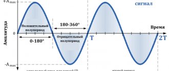
- Bipolar Signals - These electrical signals are also called alternating signals because they alternate between positive and negative values, constantly crossing zero. Bipolar signals have a periodic change in the sign of their amplitude. The most common bidirectional signal is the sine wave.
Whether unidirectional, bidirectional, symmetrical, asymmetrical, simple or complex, all electrical signals have three common characteristics:
- The period is the length of time after which the signal begins to repeat. This time value is also called the period time for sinusoids or the pulse width for square waves and is denoted by the letter T.
- Frequency is the number of times a signal repeats itself over a period of time equal to 1 second. Frequency is the reciprocal of the time period, ( *** QuickLaTeX cannot compile formula: f = 1/T *** Error message: Cannot connect to QuickLaTeX server: SSL certificate problem: certificate has expired Please make sure your server/PHP settings allow HTTP requests to external resources (“allow_url_fopen”, etc.) These links might help in finding a solution: https://wordpress.org/extend/plugins/core-control/ https://wordpress.org/support/topic/an -unexpected-http-error-occurred-during-the-api-request-on-wordpress-3?replies=37 ). The unit of frequency is Hertz (Hz). The frequency is 1 Hz and the signal repeats once every 1 second.
- Amplitude is the amount of change in the signal. It is measured in Volts (V) or Amperes (A), depending on which time dependence (voltage or current) we use.
see also
- Electrical signal
- Voltmeter
- Ammeter
- Frequency meter
- Spectrometer
- Lisajoux figures
- method of calibrated scales;
- compensation method;
- comparison method.
- Method of interference figures (Lisajous figures)
- Circular scanning method with brightness modulation
Unfortunately, it is not easy to provide all the knowledge about studying a signal shape in one article. But I tried. If you show interest in revealing the details, I will definitely write a sequel! I hope that now you understand what a signal shape study is, a signal shape, and why all this is needed, and if you don’t understand, or if you have any comments, then don’t hesitate to write or ask in the comments, I will be happy to answer. In order to gain a deeper understanding, I strongly recommend that you study all the information from the category METROLOGY AND ELECTRORADIO MEASUREMENTS
Types of electrical signals
The purpose of the story is to show what the concept of “signal” is, what common signals exist and what common characteristics they have.
What is a signal? To this question, even a small child will say that this is “the kind of thing with which you can communicate something.” For example, using a mirror and the sun, you can transmit signals over a line-of-sight distance. On ships, signals were once transmitted using semaphore flags. This was done by specially trained signalmen. Thus, information was transmitted using such flags. Here's how to convey the word "signal":
There are a huge variety of signals in nature. Yes, in fact, anything can be a signal: a note left on the table, some sound can serve as a signal to start a certain action.
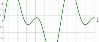
Okay, everything is clear with such signals, so I’ll move on to electrical signals, which in nature are no less numerous than any other. But they can at least be roughly divided into groups: triangular, sinusoidal, rectangular, sawtooth, single pulse, etc. All of these signals are named for what they look like when plotted on a chart.
The signals can be used as a metronome to count clocks (as a timing signal), to keep time, as control pulses, to control motors, or to test equipment and transmit information.
Electrical characteristics signals
In a sense, an electrical signal is a graph showing the change in voltage or current over time. Which in Russian means: if you take a pencil and mark time along the X axis, and voltage or current along the Y axis, and mark the corresponding voltage values at specific times with dots, then the final image will show the waveform:
There are a lot of electrical signals, but they can be divided into two large groups:
- Unidirectional
- Bidirectional
Those. in unidirectional ones, the current flows in one direction (or does not flow at all), and in bidirectional ones, the current is variable and flows either “there” or “here”.
All signals, regardless of type, have the following characteristics:
- Period is the period of time after which the signal begins to repeat itself. Most often designated T
- Frequency - indicates how many times the signal is repeated in 1 second. It is measured in Hertz. For example, 1Hz = 1 repetition per second. Frequency is the reciprocal of the period ( ƒ = 1/T )
- Amplitude - measured in volts or amperes (depending on whether the signal is current or voltage). Amplitude refers to the “strength” of the signal. How far does the signal graph deviate from the X-axis?
Types of signals
Sine wave
I think that representing a function whose graph in the picture above makes no sense is the well-known sin(x). Its period is 360o or 2pi radians (2pi radians = 360o).
And if you divide 1 second by period T, then you will find out how many periods fit into 1 second or, in other words, how often the period repeats. That is, you will determine the frequency of the signal! By the way, it is indicated in hertz. 1 Hz = 1 sec / 1 repeat per sec
Frequency and period are the inverse of each other. The longer the period, the lower the frequency and vice versa. The relationship between frequency and period is expressed by simple relationships:
| Suffix | Full meaning | Reduction | Indicates time |
| Kilo | Thousand (Kilohertz) | KHz | 1 millisecond (10-3) |
| Mega | Million (Megahertz) | MHz | 1 microsecond (10-6) |
| Giga | Billion (Gigahertz) | GHz | 1 nanosecond (10-9) |
| Tera | Trillion (Terahertz) | THz | 1 picosecond (10-12) |
Meander
Signals that resemble rectangles in shape are called “rectangular signals.” They can be divided into simple rectangular signals and meanders. A square wave is a rectangular signal in which the pulse and pause durations are equal. And if we add up the duration of the pause and the pulse, we get the meander period.
Square wave
A regular rectangular signal differs from a meander in that it has different pulse and pause durations (no pulse). See the picture below - it says a thousand words.
By the way, there are two more terms for square wave signals that you should know. They are inverse to each other (like period and frequency). These are the ratio and fill factor. The ratio (S) is equal to the ratio of the period to the pulse duration and vice versa for the coefficient. filling.
Thus, a square wave is a rectangular signal with a duty cycle of 2. Since its period is twice as long as the pulse duration.
S — duty cycle, D — duty cycle, T — pulse period, — pulse duration.
By the way, the graphs above show ideal rectangular signals. In life they look slightly different, since in no device can a signal change absolutely instantly from 0 to some value and then go back down to zero.
Triangle signal
If we climb a mountain and then immediately descend and record the change in the height of our position on the graph, we will get a triangular signal. A harsh comparison, but a true one. In triangular signals, the voltage (current) first increases and then immediately begins to decrease. And for a classic triangular signal, the increasing time is equal to the decreasing time (and equal to half the period).
If such a signal has an increasing time less or greater than the decreasing time, then such signals are already called sawtooth. And about them below.
Ramp signal
As I wrote above, an asymmetrical triangular signal is called a sawtooth signal. All these names are conditional and are needed simply for convenience.
Here's a simple introduction to electrical signals. There are many of them in nature, but the ones described above are those that occur quite often in our amateur radio business. I hope that now you will know more about them.
What to read next
- Yukio Sato. Signal Processing
- Kaganov. Radio circuits and signals
- How to use an oscilloscope and why you need it. Part I
- How to use an oscilloscope and why you need it. Part II
ps Some of the material is based on an interesting but verbose article from here. This text cannot be called a translation, so we will consider it a free retelling. Pictures are adapted to Russian =)
What is information
Information is understood as a set of information about any events, phenomena or objects intended for transmission, reception, processing, transformation, storage.
K.E. Shannon, as one of the founders of information theory, figuratively defined it as follows: “Information is a message that reduces uncertainty.”
If I tell you something that is known to you, then it will not be information for you. If I tell you what you didn’t know, reduce your uncertainty, then this will already be information for you.
THEORY OF ELECTRIC CIRCUITS
Signals can be periodic or non-periodic. Periodic ones are repeated at certain intervals. Non-recurring ones occur once and do not recur.
1 Instantaneous is the value of the signal at any time u, i, e;
2 Maximum is the largest of the instantaneous values Um, Im, Em
;
3 Scope
is the difference between the maximum and minimum signal values
Up, Ip, Ep
,
4 Period
- this is the shortest period of time. through which, the value of the variable is repeated [T]=с;
5 Cyclic frequency
is the number of oscillations of a variable in 1 s.
[f]=Hz
1kHz=103Hz
1MHz=106Hz
Dynamic range
The range of any type of analog signal is easy to calculate. It is necessary to use the difference between higher and lower volume levels, which is shown in decibels.
It should be noted that the information depends entirely on the characteristics of its execution. Moreover, we are talking about both music and the conversations of ordinary people. If we take an announcer who will read the news, then his dynamic range will be no more than 30 decibels. And if you read any work in color, then this figure will increase to 50.
What happens to the signal in the communication channel
It comes with attenuation, delay, Doppler shift, noise, and the like.
Weakening
The signal is weakened due to dispersion in space. For example, we have a radio signal source that is omnidirectional and isotropic, i.e. it radiates equally in all directions. This results in a spherical wave front. At one distance r1 and at another r2 .
Let the emitted power be 100 W, all these 100 watts are distributed throughout the entire sphere. The receiving antennas are not large, they cover only a small area of space. And the amount of power passing through a small area of space will be different at distances r1 and r2. Because the power density at distance r1 will be higher than at distance r2.
The area of the sphere is S=4pi*R^2 . And this formula appears in all formulas for estimating radio communication range. Because the radio wave is uniformly scattered in space. And in addition to the fact that the signal itself weakens as it propagates in space, the electromagnetic wave passes through a certain medium, which it tries to heat and, as a result, loses its energy.
Signal propagation delay
Despite the fact that an electromagnetic wave is the fastest we have in the universe, the speed of propagation of this wave is nevertheless finite. And measurable. For example, at 1 km the propagation delay is ~3.3 µs.
What is the effect of propagation delay? Usually, we do not know exactly the distance between the transmitter and the receiver with an accuracy of microns. And the propagation delay, which is unknown to us, we don’t know the distance and we don’t know how long it will take to receive this signal. And accordingly, we do not know the initial phase of the signal.
Doppler frequency shift
We received a signal with a frequency that differs from the one we transmitted. This gave information about the speed of the object. Doppler frequency shift occurs when we either have the receiver or transmitter moving relative to each other. Either the reflecting medium moves, the transmitter emits, the radio signal is reflected from some object, if this object also moves, then a Doppler frequency shift occurs. Read the full article “Doppler frequency shift” for more details.
Exposure to interference and noise
And on the air there are noises and the receiver’s own noise. More details about noise in a separate article.
Signal fading
Signal fading is a process when a signal randomly jumps in amplitude and phase. Sometimes the amplitude is greater, sometimes less. Highlight:
- Fast fading (interference fading) - superimposing your own copies of the signal from re-reflections with different phases. Caused by multipath signal propagation.
When there is a source, there is a receiver, there are many ways for a radio wave to propagate; one wave can come direct, another can be reflected.
For example, one wave traveled 100 km, the other 101 km, what does this lead to? If two electromagnetic waves have traveled different paths, then the phases of these signals will also be different. Accordingly, if the signals were formed in antiphase, then the signals suppressed each other, if they were formed in phase, then they strengthened each other.
Due to multipath propagation, each ray travels a different distance, causing the initial phase of each ray to be different. And when these signals are added at the receiver, they can strengthen or weaken each other. This leads to the fact that the amplitude of the resulting signal is constantly changing, and this is fast fading.
- Slow fading (shading) is the occurrence of obstacles along the path of a radio wave. If a radio wave propagates in space and encounters obstacles, these obstacles either appear or disappear.
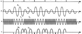
The figure below shows the nature of the change in signal amplitude over time. The solid line shows fast fading, the dotted line shows slow fading. Slow fading occurs due to shadowing, while fast fading occurs due to multipath propagation. It turns out that the amplitude constantly jumps by tens of dB.
Intersymbol interference
Occurs due to multipath propagation.