What is no-load speed (XX) of a transformer?
The amount of power transformer losses consists of the so-called copper losses and steel losses. The first are associated with the flow of load current through the winding conductors, which have a certain electrical resistance. Losses in steel are caused by eddy currents and magnetization currents arising in the magnetic circuit.
Orlov Anatoly Vladimirovich
Head of the Relay Protection and Automation Service of Novgorod Electric Networks
Ask a Question
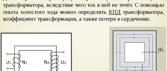
When conducting an idle test, voltage is connected to one winding, while the other remains open. The power consumed by the transformer from the network is spent to a greater extent on magnetizing the steel of the magnetic core, and to a lesser extent on heating the winding conductors, which can be neglected.
Therefore, this experiment allows us to measure the power losses in steel, called no-load losses.
Additionally, by connecting a voltmeter to the remaining open winding, you can measure the voltage on it and, based on the readings of two voltmeters, calculate the transformation ratio. But this measurement does not apply to the idling experience itself.
Idling experience during commissioning is subjected to
- All dry transformers, as well as those having a liquid non-flammable dielectric as an insulating and cooling medium.
- Oil-filled transformers with a power of more than 1600 kVA.
- Transformers for auxiliary needs of power plants, regardless of their power.
In operation, such measurements are carried out only for transformers with a power of 1000 kVA or more, and only after major repairs associated with changing the windings or repairing the magnetic circuit.
According to network rules, it is possible to carry out measurements by order of the technical manager of the enterprise after chromatographic analysis of gases dissolved in oil has given alarming results. But this applies only to power transformers with windings for voltages of 110 kV and higher.
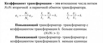
What is transformation ratio
The transformer does not change one parameter to another, but works with their values. However, it is called a converter. Depending on the connection of the primary winding to the power source, the purpose of the device changes.
These devices are widely used in everyday life. Their goal is to supply a home device with power that corresponds to the nominal value specified in the passport of this device. For example, the network voltage is 220 volts, the phone battery is charged from a 6 volt power source. Therefore, it is necessary to reduce the mains voltage by 220:6 = 36.7 times, this indicator is called the transformation ratio.
To accurately calculate this indicator, you need to remember the design of the transformer itself. Any such device has a core made of a special alloy and at least 2 coils:
- primary;
- secondary.
The primary coil is connected to the power source, the secondary coil is connected to the load, there can be 1 or more of them. A winding is a coil consisting of an electrical insulating wire wound on a frame, or without it. A complete turn of the wire is called a turn. The first and second coils are installed on the core, with its help energy is transferred between the windings.
Power transformers. Measuring the resistance of windings to direct current.
The measurement can be made using the voltage drop method or using a bridge.
The magnitude of direct current when measured is no more than 0.2 of the rated current.
When measuring the resistance of one winding, the other windings must be open in all positions of the switching device.
A rechargeable battery is used as a DC power source for measurements. It is allowed to use a rectifier device with a voltage ripple of no more than 1%.
Measurement using the voltage drop method . If the measured resistance is less than 10 Ohms, then use the circuit for measurements 7.1a. , if the resistance is more than 10 Ohms, then use the circuit for measurements 7.1b. To reduce the current installation time, use a 7.1V circuit. Reducing the current setting time is achieved by briefly forcing the current by closing resistor R. The value of resistor R should be 5–10 times the resistance of the winding being measured.
Measurement using a bridge is carried out in accordance with the instructions for the measuring bridge.
Resistances less than 0.0001 Ohm are measured using a double measuring bridge.
Measurement of dielectric parameters of insulation . These parameters include insulation resistance R loss tangent tg and insulation capacitance C.
Measuring instruments:
1. A DC voltage megohmmeter of at least 2500 V. It is permissible to use a 1000 V megohmmeter to measure the insulation resistance of a transformer with a higher voltage up to 10 kV inclusive.
It is recommended to use a megohmmeter type F4108 or other accuracy class of at least 2.5.
2. Measuring bridge powered by an alternating voltage source of 50 Hz for measuring tg and C windings.
The winding temperature during measurement is not less than + 10 C.
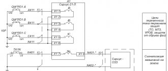
Measuring the insulation resistance of windings and determining the absorption coefficient . Insulation resistance measurements are carried out according to the diagram.
The winding on which the grounding part
produced transformer
NN VN, tank
HV LV, tank
HV + LV tank
The terminals of the windings (LV - low voltage winding, HV - high voltage winding) on which the measurement is made are connected to each other.
Before each measurement, the winding under test is grounded for 120 seconds.
When measuring insulation resistance, the count is made twice: after 15 and 60 seconds. after the voltage at which the measurement is made appears on the transformer. The actual insulation resistance is the insulation resistance measured after 60 s.
The absorption coefficient is
R is the value of R when counted 60 s after the voltage at which the measurement is made appears on the transformer, R is the same after 15 s.
Measuring tg C of windings. The connection of the windings during measurements is the same as when measuring insulation resistance. The measurement is carried out using an AC bridge according to the circuits
a) b)
a) – inverted diagram; b) – normal scheme; T – supply transformer;
C1 – exemplary capacitor; R2 – adjustment resistor; C2 – control capacitor; Cx – test object; G – galvanometer.
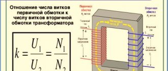
Definition and formula of transformer transformation ratio
It turns out that the coefficient is a constant value showing the scaling of electrical parameters; it completely depends on the design features of the device. For different parameters, k is calculated differently. There are the following categories of transformers:
- by voltage;
- by current;
- by resistance.
Before determining the coefficient, it is necessary to measure the voltage on the coils. GOST states that such a measurement must be made at idle. This is when there is no load connected to the converter, the readings can be displayed on the nameplate of that device.
Then the readings of the primary winding are divided by the readings of the secondary, this will be the coefficient. If there is information about the number of turns in each coil, the number of turns of the primary winding is divided by the number of turns of the secondary. In this calculation, the active resistance of the coils is neglected. If there are several secondary windings, find their own k for each.
Analysis of idle speed measurement results
During acceptance tests and overhauls, the data obtained is compared with the report of the corresponding tests carried out at the plant after the manufacture of the transformer. A discrepancy of more than 5% is not allowed.
For single-phase transformers in the same cases, the power loss should not differ from the original value by more than 10%.
In operation, only the no-load current is measured based on experience with the rated voltage or the power loss at a reduced one. PTEEP does not normalize deviations from the norm.
However, if damage is suspected in a transformer, the method of measuring losses using three consecutive tests gives a very valuable result. Since the windings of the transformer phases are in unequal conditions, it is possible not only to calculate whether there is a defect there, but also to determine the defective phase.
The path of the magnetic flux when exciting terminals AB and BC is the same. Therefore, the power losses for experiments at these phases will not differ. When the AC phases are excited, the path traveled by the magnetic flux is longer, so the power losses will be 25-50% higher than the previous ones. By comparing these indicators, it is possible to identify at which phase there is a defect.
Methodology and theoretical basis for conducting the experiment
The idle mode of the transformer is achieved relatively simply. To do this, it is enough to disconnect the load from all its windings, leaving them open, and then turn it on to the network. For the accuracy of the experiment, it is desirable that the network voltage be equal to the nominal voltage for a given unit.
A current Io flows through the primary winding, called current XX. Its value does not exceed 3-10% of the nominal value. Let us remind you that there is no load on the secondary winding, so it is worth explaining the processes taking place inside in order to understand where this current comes from.
Current XX creates a magnetic flux Fo in the magnetic core, crossing the turns of the primary and secondary windings. Due to it, a self-induction emf E1 appears on the primary winding, and a mutual induction emf E2 appears in the secondary winding.
Self-induction emf E1 has little effect on the primary voltage U1. If you connect a voltmeter to it, it will measure the value of U1. And the emf E2 can practically be considered the voltage U2, since there is no load current. For example, the no-load voltage of a welding transformer is about 60V, this is emf E2. When an arc occurs, E2 sharply drops to tens of volts - this is the value under load U2.
Net power losses in a transformer during its operation are divided into two components: losses in copper and losses in steel. Copper loss refers to the power dissipated as heat in the windings. When conducting the XX experiment, the current through the primary winding is quite small, and losses in copper can be neglected.
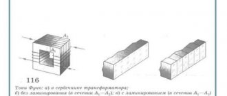
Operation of a transformer in idle mode is accompanied by power consumption to create a closed magnetic flux in its magnetic circuit. This is called the loss power in steel. It goes to heating the magnetic circuit plates. It is assembled from individual thin sheets of a special alloy, insulated from each other with varnish. No welding is used during assembly, only bolted connections. This is done to minimize eddy currents that occur due to the fact that the magnetic flux is variable.
If the insulation between the plates is broken, the eddy currents arising between them heat the magnetic circuit. This leads to further destruction of the varnish layer. At the same time, the power losses in the steel increase, which will increase the no-load losses of the transformer.
Operating modes of transformer devices
At the moment, there are about ten types of different transformer devices. All of them are united by a single principle of changing alternating voltage and structural similarity. Accordingly, each of the transformers is capable of operating in three main modes: no-load, short circuit and load. The idle mode allows you to make a number of measurements, the data of which is necessary for a comprehensive analysis of the efficiency of the devices. The first tests are carried out to determine and verify compliance with the passport values of the technical data of the transformer as a whole and each of its components in particular before putting the device into operation. Commissioning works reveal hidden faults and allow them to be corrected before intensive use of the device. Some of them are carried out at the assembly stage, and some are carried out after the oil has been poured.
Transformer oil testing
Take at least 0.5 liters of oil into a clean and dry sample vessel. Let it sit in the spark gap for 20 minutes. Then the voltage increases until breakdown. For evaluation, 6 breakdowns are usually taken.
The first breakdown is not taken into account.
And all because it requires testing in hot oil. After all, we need to find out the breakdown voltage for a transformer operating for a long time in normal mode, and not just after startup. An interval of up to 10 minutes is maintained between each check. The arithmetic mean of five breakdowns should be:
- at Utransf. up to 15 kV - more than 25 kV;
- Utransf. from 15 to 30 kV - over 30 kV.
Stages of commissioning tests ↑
Primary performance testing is carried out in several directions at once. Mandatory ones include:
- Measurements of data on idle losses.
- Measurements of ohmic resistance of all existing windings.
- Determination of transformation ratio.
- Testing a group of winding connections.
- Insulation check.
In this case, the sequence of performing all types of the above tests plays an important role.
Engineering has all the necessary tools for high-quality diagnostics of transformers, a well-coordinated team of professionals and licenses that give the right to carry out all the necessary tests and measurements. By choosing the ProfEnergia electrical laboratory, you are choosing reliable and high-quality operation of your equipment!
If you want to order diagnostics of transformers or ask a question, call .