Due to the presence of a large number of international standards and technical solutions, electronic devices can be powered from various ratings. But not all of them are freely available, so to obtain the required potential difference you will have to use a converter. Such devices can be found both on the open market and assembled independently from radio components.
Due to the presence of two types of electric current: direct and alternating, the question of how to reduce the voltage should be considered in terms of each of them separately.
What is the voltage drop across a resistor
Electric current passing through a circuit experiences resistance, which can change under the influence of various environmental conditions (extremely low temperatures or heat) and may depend on the characteristics of the particular conductor. For example, the thinner the conductor or longer, the higher it is.
The value of its value is influenced by the following factors:
- current strength;
- length of conductive parts;
- voltage;
- conductor element material;
- heating (temperature);
- cross-sectional area.
Resistors can be divided into constant, variable and trimming. Their main difference from each other is the ability to change the resistance indicator. The most common ones are fixed resistors - this indicator cannot be changed in them, which is why they got that name. Variables differ in that the resistance value in them can be adjusted. In a trimmer resistor it can also be changed, but the difference between this type is that it is not designed for frequent changes of the parameter. Trimmer resistors are made in a more compact package compared to variables.
To calculate the voltage drop across a resistor, you need to remember that the reduction in load applied to the entire circuit (that is, the voltage connected to the circuit) can be obtained both for the entire circuit and for any element in the circuit. The voltage is reduced due to the resistance that the conductors have.
The voltage drop across the resistor depends on the strength of the current passing and the characteristics of the conductors. Temperature and current readings also matter. For example, the voltage measured by a voltmeter on a light bulb connected to a 220 V network will be slightly lower due to the resistance that the light bulb has.
Power supplies have different voltage levels. This value may exceed what is needed at the output. To prevent the load that needs to be powered from burning out, it is often necessary to lower the voltage, including using resistors.
Voltage comparison table
| Power supply | Voltage |
| NiCd battery | 1.2 V |
| Lithium iron phosphate battery | 3.3 V |
| Battery type "Krona" | 9 V |
| Car battery | 12 V |
| Truck battery | 24 V |
In this case, the resistor should reduce the current flowing through the circuit. In this case, the current does not turn into heat, it is precisely its limitation that occurs. That is, when a resistor is connected to the circuit, the current will drop - this is the work of the resistor, during which the element heats up.
In general, voltage drops can be calculated using a simple formula that relates the indicators to each other.
But in some cases, for example, when connecting resistances in parallel, it is more difficult to calculate the required value. In this case, using a special formula, you will need to bring the resistance of parallel branches to one number:
R = R1*R2 / (R1+R2)
If necessary, other resistances that add up to this value are also taken into account (for example, resistance of the wire and power supply).
How to get 12V from improvised means
The easiest way to get 12V voltage is to connect 8 1.5V AA batteries in series.
Or use a ready-made 12V battery marked 23AE or 27A, the kind used in remote controls. Inside it is a selection of small “tablets” that you see in the photo.
We looked at a set of options for getting 12V at home. Each of them has its own pros and cons, varying degrees of efficiency, reliability and efficiency. Which option is better to use, you must choose yourself based on your capabilities and needs.
It is also worth noting that we did not consider one of the options. You can also get 12 volts from an ATX computer power supply. To start it without a PC, you need to short-circuit the green wire to any of the black ones. 12 volts are on the yellow wire. Typically, the power of a 12V line is several hundred watts and the current is tens of amperes.
Now you know how to get 12 Volts from 220 or other available values. Finally, we recommend watching a useful video on the topic:
You probably don't know:
- How to desolder radio components from boards
- How to check a diode bridge
- How to determine the capacitance of a capacitor
- Marking resistors by power and resistance
Published: 05/08/2018 Updated: 05/08/2018
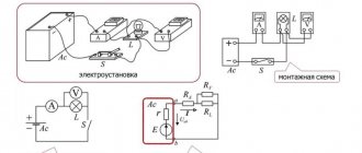
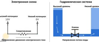
Ohm's law for an electrical circuit
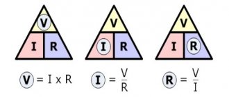
The basis for calculating the input and output voltage of a circuit is Ohm’s law, familiar from school physics courses. The basic formula for calculating the voltage on a section of a circuit looks like this:
The voltage in the AC circuit can be determined using the following formula:
U=I/Z, where
in this formula, Z stands for the resistance (ohms) that was obtained throughout the circuit.
In some cases, indicators cannot be calculated directly from these formulas.
- In cases where conductors or dielectrics are exposed to high voltage.
- In cases of rapidly changing electromagnetic fields during the passage of high frequency currents. In this case, it is also necessary to take into account the inertia of charge-carrying particles.
- Under conditions of superconductivity properties appearing if the circuits operate at extremely low temperatures.
- When a conductor is heated by current flowing through it.
- For LEDs. The relationship between current and voltage drop in this case is nonlinear.
- For processes in semiconductor-based devices.
Resistor resistance unit
In the International System of Units (SI), resistance is measured in ohms, a unit named after the physicist Georg Ohm, who also discovered the famous law for the electrical circuit. The international designation looks like this: Ω. The physical meaning of this unit is as follows:
The resistance of the conductor is 1 ohm with a current of 1 A and a voltage at the ends of the conductors of 1 V.
It can be measured using a device called an ohmmeter.
For reference. In the SGS system, resistance does not have a specific name, but its extensions use stat (1 statΩ; calculated as a current of 1 statampere divided by a voltage of 1 statvolt) and abom (1 abΩ = 1*10-9 Ohm, nanoohm; its calculation is a current of 1 ampere divided by a voltage of 1 abvolt). The dimension of this quantity in the SGSE and Gaussian system is equal to TL−1, in the SGSM it is LT−1. The reciprocal quantity is electrical conductivity, its unit of measurement is siemens (Sm), statsiemens or absiemens for different systems, respectively.
There is a wide variety of resistors with a wide range of standard resistance values. Let's consider the relationship between these denominations and the various prefixes used to designate them.
Prefix kilo- (kilo-ohm):
1 KOhm is equal to 1000 Ohms
Prefix mega (megaohm):
1 MΩ corresponds to 1000 KΩ or 1,000,000 Ω
Often, resistor indicators are applied directly to their body. It is very comfortable. Let us consider the designation of their denominations in more detail.
The value of a resistor is the same as its resistance. Previously, resistors were quite large, so all values were written entirely on their bodies using ordinary letters. In addition to the resistance on the resistor, they could also indicate the accuracy class or power dissipation.
Resistance is the main characteristic of a resistor. What it is and how it is calculated was described above, so now we will dwell in more detail on the features of their designations.
To indicate a value not exceeding 1KOhm, an R is placed after the number indicating the resistance value (or the value is indicated without a letter at all). On resistors that were produced a long time ago, you can find the word Ohm. Later the accepted marking changed, it is now used in the format:
integer value - R - fractional remainder
Examples of notation:
300 = 300 Ohm 200 R = 200 Ohm
Modern notations look like this:
4R02 = 4.02 Ohm 2R2 = 2.2 Ohm
If the value is less than 1 ohm, then the zero at the beginning of the designation is omitted:
0R5 = R5 = 0.5 Ohm
If the resistance is more than a thousand ohms, then special prefixes (mega-, kilo-) are used to simplify writing. Very large values of this quantity are almost never encountered, so the need for the Tera- and Giga- prefixes arises extremely rarely. Examples of notation:
Choosing the right brand of linoleum for film flooring
It is believed that linoleum is a synthetic floor covering that, when heated, releases substances that are harmful to human health. Another criticism of this coating is its poor ability to withstand heat. High temperatures can cause linoleum to become severely deformed. And initially, the coating was created not to transfer heat, but to protect against the cold penetrating from below.
But no one will argue that linoleum is distinguished by reasonable prices and ease of installation, and these positions give it special popularity.
New technologies have made it possible for manufacturers to develop new types of this coating. These include those that transfer heat well, withstand moderate heat, and do not emit harmful fumes.
There are five main types of material:
- alkyd (griftal);
- colloxylin;
- rubber;
- PVC;
- natural.
It should be noted right away that the materials of the first three groups are definitely not suitable for use with heated floors. Each type reacts poorly to heating, and rubber linoleum is not used at all for installation in residential premises.
The most popular is PVC linoleum. It has many design solutions and varies in thickness, is relatively safe, and is reasonably priced. After installation, the new coating emits characteristic odors, which soon disappear. Such linoleum is not considered dangerous and is used in premises intended for human habitation. If you decide to purchase this particular option, carefully study its labeling. As a rule, the manufacturer makes a corresponding note that under such linoleum it is allowed to install a warm floor.
Natural material is an advanced version of the flooring market. This linoleum contains components of natural origin - cork bark, pine resin, linseed oil, natural dyes, powdered limestone.
When heated, such linoleum does not emit hazardous substances, but is sensitive to high temperatures, so it should be used in tandem with a heated floor very carefully. By the way, this recommendation also applies to PVC linoleum.
Natural linoleum
The cost of such a natural coating is quite high, but its resistance to wear completely compensates for this disadvantage. The material does not change color and has excellent fire resistance.
When deciding on this type of coating, it is recommended to pay attention to its thickness. Excessively thin linoleum will emphasize every unevenness of the base, while thicker linoleum will reduce the heating efficiency
Resistor power characteristic
The power of the electric current in a section of the circuit can be found through the product of the current strength for it and the voltage in this section. The formula looks like this:
P= I * U (product of current and voltage), where
P - power value (W).
The resistor does work to reduce the current, while it releases heat into the surrounding space. But if the work to limit the current is very great and heat is generated too quickly, then it will overheat and may burn out, since it will not have time to dissipate it. This point should be taken into account when selecting the resistor power
Important! The power of a resistor is a very important parameter that must be taken into account when developing electrical circuits for devices. The power of a resistor is characterized by the maximum amount of current that it can withstand without overheating or failing.
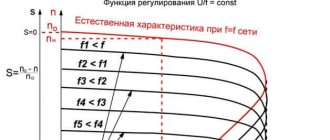
How to increase the current in the generator?
The current in the generator directly depends on the load resistance parameter. The lower this parameter, the higher the current.
If I is higher than the nominal parameter, this indicates the presence of an emergency mode - frequency reduction, generator overheating and other problems.
For such cases, protection or disconnection of the device (part of the load) must be provided.
In addition, with increased resistance, the voltage decreases, and U increases at the generator output.
To maintain the parameter at an optimal level, regulation of the excitation current is provided. In this case, an increase in the excitation current leads to an increase in the generator voltage.
The network frequency must be at the same level (constant).
Let's look at an example. In a car generator, it is necessary to increase the current from 80 to 90 Amperes.
To solve this problem, you need to disassemble the generator, separate the winding and solder the lead to it, followed by connecting the diode bridge.
In addition, the diode bridge itself is changed to a part with higher performance.
After this, you need to remove the winding and a piece of insulation in the place where the wire is to be soldered.
If there is a faulty generator, the lead is bitten off from it, after which the legs of the same thickness are built up using copper wire.
After soldering, the joint is insulated with heat shrink.
The next step is to buy an 8-diode bridge. Finding it is a very difficult task, but you have to try.
Before installation, it is advisable to check the product for serviceability (if the part is used, a breakdown of one or more diodes is possible).
After installing the bridge, attach the capacitor, and then a 14.5-volt voltage regulator.
You can purchase a pair of regulators - 14.5 (German) and 14 Volts (domestic).
Now the rivets are drilled out, the legs are unsoldered and the tablets are separated. Next, the tablet is soldered to a domestic regulator, which is fixed with screws.
All that remains is to solder the domestic “pill” to the foreign regulator and assemble the generator.
How to lower voltage using a resistor
To prevent the load that needs to be powered from burning out, it is often necessary to reduce the input voltage. The easiest way to achieve this is to use a two-resistor circuit, better known as a voltage divider. The classic scheme looks like this:
In this case, the voltage is supplied to two resistors using a parallel connection, and at the output it is received from one. The selection of resistor values is carried out according to the formula so that the voltage removed at the output is some part of the supplied one. You can calculate a resistor to reduce the voltage using a formula based on Ohm's law:
Uout= (Uin*R2)/(R1+R2), where
Uin – input voltage, V;
Uout – output voltage, V
R1 – resistance index. 1st resistor (Ohm)
R2 – resistance index. 2nd element, (Ohm)
Selecting a resistor to reduce voltage
To select the required resistor resistance, you can use ready-made online calculators or programs for simulating the operation of electronic circuits. Electrical circuit simulators are capable of not only calculating the output voltage depending on the resistance of the elements and the method of their connection, but also have functionality that allows you to visualize how the current and voltage across the resistor drops. For example, the EveryCircuit application allows you to change the parameters of elements in the circuit, select the simulation speed, and obtain data at various points. In this case, you can observe the dynamics of changes in values using the rotating dial in the lower right corner to enter input parameters.
There are also a number of free emulation programs that allow you to perform, among other things, calculations of a resistor when the voltage drops, for example:
- EasyEDA;
- Circuit Sims;
- DcAcLab;
and others.
In the article, we became acquainted with the concept of resistance, learned about its units of measurement, the marking of resistors, programs that emulate the operation of a circuit and facilitate the selection of the desired resistance, and also looked at examples of calculating the voltage drop across a resistor.
Physical definition
A resistor is an element used in an electrical circuit and does not require a power source for its operation. It is designed to transform current into voltage and vice versa. In addition, it can convert electrical energy into thermal energy and limit the amount of current. But before calculating the voltage drop across a resistor, it is advisable to understand the essence of this process.
A resistor is a very common element characterized by a number of parameters. The main ones are:
- resistance;
- the amount of energy dissipated;
- operating voltage;
- power;
- resistance to environmental influences;
- parasitic component.
A passive electrical element is indicated in the diagram as a rectangle with two terminals from the middle of its sides. In the center of the figure, power can be indicated in Roman numerals or dashes. For example, a vertical stripe indicates the element's withstand power of 1 W. The crossed out rectangle in the notation in the diagram indicates that such a resistor is variable.
Resistors can be produced with constant and variable resistance. A type of the latter are tuning elements. The only difference between them and variables is the way they are set to the desired value.
On diagrams and in technical literature, the device is designated by the Latin letter R, next to which the serial number and its denomination are indicated in accordance with the International System of Units (SI). For example, R12 5 kOhm is a five kilo-ohm resistor located in the circuit under number 12.
When manufacturing an element, a resistive layer is used, which can be film or volumetric. It is applied to a dielectric base and covered with a protective film on top.
Resistance value
Resistance is a fundamental quantity in electrical processes. Its meaning is invariably related to current and voltage. Their general dependence is described using Ohm's law: the current strength arising in a section of the circuit is directly proportional to the potential difference between the extreme points of this section and inversely proportional to its resistance. From this law the resistance is found using the following formula:
R = U / I, where:
- R is the resistance in the circuit section, Ohm.
- I is the current strength passing through this section, A.
- U is the potential difference at the nodes of a part of the circuit, V.
In fact, the resistance of an element is determined by its physical structure and is caused by the vibrations of atoms in the crystal lattice. Therefore, all materials are classified as conductors, semiconductors and dielectrics depending on their ability to conduct electricity.
Current is the directed movement of charge carriers. For it to occur, the substance must have free electrons. If an electric field is applied to such a physical body, then the charges it moves will begin to collide with inhomogeneities in the structure. These defects are formed due to various impurities, violation of lattice periodicity, and thermal fluctuations. By hitting them, the electron expends energy, which is converted into heat. As a result, the charge loses momentum, and the magnitude of the potential difference decreases.
But Ohm's law cannot be applied to all substances. In electrolytes, dielectrics and semiconductors, a linear relationship between the three quantities is not always observed. The resistance of such substances depends on the physical parameters of the conductor, namely its length and cross-sectional area, and it is sensitive to temperature changes.
This dependence is described using the formula R = p * l / S. That is, the resistance is directly proportional to the length and inversely proportional to the area of the conductor. The value p is called resistivity and is determined by the type of material. Its meaning is taken from the reference book.
Resistor impedance
Ohm's law applies to an ideal resistor that has no parasitic resistance. The total resistance (impedance) is determined based on the equivalent circuit. Accurate calculation of resistance to reduce voltage must be carried out using other formulas. The equivalent circuit of a resistor, in addition to active impedance, also contains capacitive and inductive reactance.
The first leads to a slow accumulation of charge, which dissipates when the direction of the current changes. The larger the parasitic capacitance, the longer it takes to charge. Accordingly, the faster the current changes its direction, the lower its capacitance. The second is characterized by a magnetic field, whose appearance prevents the current from changing direction, therefore, the faster the current changes its movement, the greater the inductive reactance becomes.
Impedance is calculated using the formula: I = U/Z, where Z = (R2+(Xc-Xl)2)½. Where:
- R is the active value, R = p*l/s.
- Xc is a capacitive value, Xc = 1/w*C.
- Xl is an inductive quantity, Xl = w*C.
- w is the cyclic frequency, w = 2πƒ.
Knowing the total resistance of the resistor, you can more accurately calculate the voltage drop in it. But to measure parasitic components you will need to use highly specialized instruments. In conventional calculations, resistance is calculated taking into account only its active value, and parasitic values are taken as negligible.